
Related Manuals for OHAUS I-DT61PW


Summary of Contents for OHAUS I-DT61PW
- Page 1 Defender 6000 Indicators Instruction Manual 5 Commonwealth Ave Woburn, MA 01801 Phone 781-665-1400 Toll Free 1-800-517-8431 Visit us at www.TestEquipmentDepot.com...
-
Page 3: Table Of Contents
ONNECTIONS 2.3.1 Opening the Housing ............................9 2.3.2 Scale Base without EasyConnect Connector ....................11 2.3.3 Communication Interface Cable to i-DT61PW ....................14 2.3.4 RS232 Interface Cable to i-DT61XWE ......................15 ..............................15 OUNTING RACKET OPERATION ..............................16 ............................16... - Page 4 4.7.4 Ethernet Configuration ..........................40 4.7.5 Analog Configuration ............................ 40 ................................. 40 EMORY 4.8.1 Memory menu (for i-DT61PW model) ......................40 4.8.2 USB memory (for i-DT61XWE model) ......................40 4.8.3 Alibi Memory (for i-DT61XWE model) ......................41 I/O ( -DT61XWE ) ........................
-
Page 5: Introduction
Any other type of use and operation beyond the limits of technical specifications, without written consent from OHAUS, is considered as not intended. This instrument complies with current industry standards and the recognized safety regulations; however, it can constitute a hazard in use. -
Page 6: Overview Of Parts And Controls
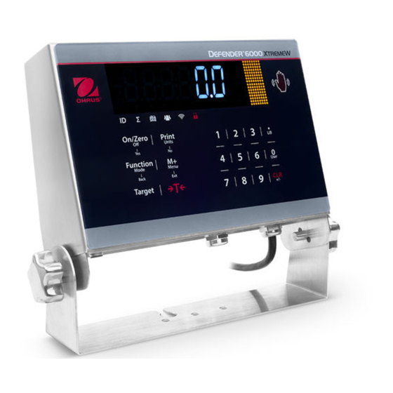
EN-4 Defender 6000 Indicators 1.3. Overview of Parts and Controls Figure 1-1 i-DT61PW Indicator Item Description Control Panel Front Housing Screws (6) Adjusting Knobs (2) Mounting Bracket Load Cell Connector Rear Housing Figure 1-2 i-DT61XWE Indicator Item Description Control Panel... -
Page 7: Mainboard
Defender 6000 Indicators EN-5 Mainboard 1.4. .Figure 1-3 i-DT61PW Mainboard Item Description IR Communication connector (J6) Security Switch (SW1) Load Cell connector (J7) Load Cell Terminal Block (J8) Figure 1-4 i-DT61XWE Mainboard Item Description Item Description Alibi Memory Board connector (J19) -
Page 8: Control Functions
EN-6 Defender 6000 Indicators 1.5. Control Functions i-DT61PW Control Panel i-DT61XWE Control Panel Button Primary On/Zero Print Function Target Tare Function If the Sends the Initiates an Accumulates Sets Enters/clears (Short Press) terminal is current value application the weight or under/over a tare value;... - Page 9 Note: for i-DT61XWE model, press the button together for three seconds can lock all buttons. Perform the same procedure again to unlock all buttons. When all buttons are locked, the icon will be lighted. Figure 1-5 i-DT61PW Display Item Description Item Description Range symbol(not used)...
- Page 10 EN-8 Defender 6000 Indicators Figure 1-6 i-DT61XWE Display Item Description Item Description NET symbol Wi-Fi symbol Center of Zero symbol Lock symbol Negative symbol Dynamic (tilde) symbol Stable weight symbol Battery symbol (not use) Preset Tare, Tare symbols Pound, Ounce, Pound:Ounce symbols Pointer symbols Percent symbol ID symbol...
-
Page 11: Installation
Defender 6000 Indicators EN-9 2. INSTALLATION Unpacking Unpack the following items: i-DT61PW or i-DT61XWE indicator 6 cells of D size dry batteries (i-DT61PW only) Mounting bracket Knobs (2) Quick installation guide Instruction manual External Connections 2.2.1 Scale Base with EasyConnect... - Page 12 EN-10 Defender 6000 Indicators Once all connections are made, re-attach the front housing. i-DT61XWE Remove the four hex head screws from the bottom housing. Open the housing by carefully pulling the bottom housing backward. Once all connections are made, re-attach the bottom housing. Note: The screws should be tightened to 2.5 N•m (20-25 in-lb) torque to ensure a watertight seal.
-
Page 13: Scale Base Without Easyconnect Tm Connector
2.3.2 Scale Base without EasyConnect Connector For connecting bases (which do not have the EasyConnect connector) to an i-DT61PW or an i-DT61XWE, a load cell cable gland kit (P/N 30379716) is available as an accessory. Removing the pre-installed Load Cell connector and wiring harness. - Page 14 EN-12 Defender 6000 Indicators i-DT61XWE Place the terminal down, and unscrew the screws marked in the following graphic. Pull out the bottom of the terminal. Use a screw driver to unscrew the sealing cover.
- Page 15 Installing Load Cell Cable and Connectors In order to meet certain electrical noise emission limits and to protect i-DT61PW and i-DT61XWE from external influences, it is necessary to install a ferrite core on the load cell cable connected to the terminal. The ferrite core is included with the terminal.
-
Page 16: Communication Interface Cable To I-Dt61Pw
EN-14 Defender 6000 Indicators Main Board Wiring Connections Once the i-DT61PW and i-DT61XWE enclosure is opened, connections can be made to the terminal blocks on the main board as shown in Figure 2-2. i-DT61PW i-DT61XWE Load Cell Terminal Figure 2-2... -
Page 17: Rs232 Interface Cable To I-Dt61Xwe
Attach the bracket to a wall or table using fasteners (not supplied) that are appropriate for the type of mounting surface. The bracket will accommodate up to 6 mm (1/4”) diameter screws. Locate the mounting holes as shown in Figure 2-8 and 2-9. Figure 2-8 i-DT61PW Mounting Bracket Dimensions Figure 2-9 i-DT61XWE... -
Page 18: Operation
EN-16 Defender 6000 Indicators 3. OPERATION Turning the Scale On/Off To turn the scale on, press and hold the On/Zero Off button for 1 second. The scale performs a display test, momentarily displays the software version, and then enters the active weighing mode. To turn the scale off, press and hold the On/Zero Off button until is displayed. -
Page 19: Check
Use this application to compare the weight of items to a target weight range. This mode is available for Weighing, Counting, Percent, and Dynamic. 3.2.3.1 Set Check Limits i-DT61PW Press the Target button from Weighing, Counting, Percent or Dynamic mode to set check limits. UNDEr The display shows Press the Yes button to edit the under value. -
Page 20: Application Settings
Long press the Target button until the display shows the under and over values. Press the CLR button of i-DT61XWE indicator or the button of i-DT61PW indicator, the display shows Clr.CHk . Press the Yes button to clear both the under and over values. -
Page 21: Counting Mode
Note: if no APW has been set before, step 3 and 4 will be omitted. 3.3.2 Establish an APW To establish an APW: Follow the previous step 4. i-DT61PW: PUt.10 The display shows the sample size . To change it, short press the No button several times until you see the value you want. -
Page 22: Percent Mode
You can press the【】 button to tare. The center of zero, PT or NET icons will light as appropriate. - - - - - For i-DT61PW model, during the capture process, the display shows rEF.Err If the reference weight is less than 100d during the capture process, the display will show for 1.5... -
Page 23: Dynamic Mode
Defender 6000 Indicators EN-21 Dynamic Mode Use this application to weigh an unstable load, such as a moving animal. 3.5.1 Enter the Mode To enter the Dynamic Weighing Mode from any application mode: dYNAmM Press and hold the Mode button until is displayed. -
Page 24: Filling Mode
EN-22 Defender 6000 Indicators Note: you cannot disable Dynamic if you are in the mode currently. Filling Mode Use this application to fill a container to a pre-determined target weight. Note: filling mode is only available for i-DT61XWE model. 3.6.1 Enter the Mode To enter the Filling mode from any application mode: FIll Press and hold the Mode button until... -
Page 25: Application Settings
Defender 6000 Indicators EN-23 After that to fill the third time, if the total load is now more than or equal to SP2 while less than SP3, the first two columns display green, the third orange, and others red. To load the fourth time, if the total load is now more than or equal to SP3 while less than SP4, the first three columns display green, and the forth one orange. -
Page 26: Menu Settings
The User Menu allows the customizing of scale settings. Note: Additional Sub-Menus may be available if Interface Options are installed. See Interface User Manual for the additional setting information. Menu Navigation 4.1.1 User Menu For i-DT61PW model C.A.L S.E.t.U.P r.E.A.d mM.O.d.E U.n.i.t... -
Page 27: Button Navigation
Defender 6000 Indicators EN-25 Zero Range setting is locked at 2%. Stable Range setting is locked at 1d. Auto-Zero Tracking setting is locked at 0.5d. Filter and Units are locked at their current settings. Stable Only is locked to be On. ... -
Page 28: Calibration Menu
To change the calibration point: i-DT61PW: short press the No button several times until the desired digit appears. Short press the Yes button to accept the digit and move to the next one. Repeat the process until all the digits are correct. -
Page 29: Linearity Calibration [ Lin ]
To change the calibration point: i-DT61PW: short press the No button several times until the desired digit appears. Short press the Yes button to accept the digit and move to the next one. Repeat the process until all the digits are correct. -
Page 30: Calibration Test [ C.test ]
To change the test calibration weight: i-DT61PW: short press the No button several times until the desired digit appears. Short press the Yes button to accept the digit and move to the next one. Repeat the process until all the digits are correct. -
Page 31: Setup Menu
Defender 6000 Indicators EN-29 Setup Menu Enter this menu S.E.t.U.P to set scale parameters. Default settings are in bold. For i-DT61PW model Sub-Menu (in Menu Sub-Menu Options Options (in segment) segment) Reset reset no, yes NO, yes Capacity Unit C.UNIt... - Page 32 Power On Unit Set the unit that will be displayed at Power On. AUtO = last unit in use when turned off = kilograms = grams = pounds = ounces lb:oz = pound ounces = metric tonne (only available for i-DT61PW model)...
- Page 33 Defender 6000 Indicators EN-31 tArE] Auto Tare Set the automatic tare functionality. = automatic tare is disabled. = the first stable gross weight is tared. ACCept = stable gross weights within the acceptable limits are tared (in Check mode). ACCUmM Accumulation Set the accumulation functionality.
- Page 34 EN-32 Defender 6000 Indicators Ir.FUNC IR Function Define the operation for the Infrared Radiation Sensor. ZerO = the scale performs zero operation equal to pressing the Zero button. tare = the scale performs tare operation equal to pressing the button. Print = the scale performs print operation equal to pressing the Print button.
-
Page 35: Readout Menu
Off, 0.5d, 1d, 3d OFF, 0.5d, 1d, 3d LIGHt Bright Level (i-DT61XWE) Low, Medium, High mMEd, HIGH, LOwW B.LIGHt Back Light (i-DT61PW) Off, On, Auto OFF, ON, AUtO Read Out S.SAuEr OFF, 1, 2, 5 (i- Off, 1min, 2min, 5min (r.E.A.d) - Page 36 = backlight is disabled. = backlight is enabled. AUtO = backlight is disabled after 5 seconds of no activity. Note: This setting is only avaliable for i-DT61PW model. SCreeN Screen Set whether the screensaver is enabled after the selected time period.
-
Page 37: Unit Menu
Kilogram (kg) Pound (lb) Ounce (oz) Pound:Ounce (lb:oz) Tonne (t) (only available for i-DT61PW model) Note: Due to national laws, the indicator may not include some of the units listed. If the Security Switch is turned on, the Units are locked at their current setting. -
Page 38: Communication
EN-36 Defender 6000 Indicators P.ID Project ID Set the Project identification number. To set the number, short press the No button several times until the desired number appears. Short press the Yes button to accept the number and move to the next digit. Repeat the process until all the digits are correct. -
Page 39: Print Menu
Defender 6000 Indicators EN-37 PArItY Parity Set the data bits and parity. 7 EVEN = 7 data bits, even parity 7 ODD = 7 data bits, odd parity 7 NONE = 7 data bits, no parity 8 NONE = 8 data bits, no parity StOP Stop bit Set the number of stop bits. - Page 40 EN-38 Defender 6000 Indicators reset Reset Reset the Print menu to factory defaults. = do not reset. = reset ASSIGN Assignment dEmMAN Demand If Demand is selected, the sub-menu Stable Only will display. Set the printing criteria. = values are printed immediately, regardless of stability. = values are printed only when the stability criteria is met.
- Page 41 EN-39 Defender 6000 Indicators tEmMp Template This sub-menu is used to define the format of the data output to a printer or computer. SImMp = only prints result and unit CUst1 = customized printout format. CUst2 = customized printout format. CUst3 = customized printout format.
-
Page 42: Rs485 Configuration
Please refer to Analog Configuration in the Defender 6000 Analog Kit Instruction Manual. Memory The Memory menu is different for i-DT61PW and i-DT61XWE. Please check the following sections for details. 4.8.1 Memory menu (for i-DT61PW model) StatUs Status To enable or disable the memory function. -
Page 43: Alibi Memory (For I-Dt61Xwe Model)
Defender 6000 Indicators EN-41 To enable USB memory: C.A.L After you insert a USB flash drive, long press the Menu button until you see mM.e.mM.O Short press the No button several times to navigate until you see . Press the Yes button. Short press the No button to navigate until you see . - Page 44 EN-42 Defender 6000 Indicators Pull out the bottom of the terminal. Take out the Alibi memory board and prepare to install it in the circled place. Insert the Alibi memory board into the slot as shown below. Please make sure the pins are properly inserted.
- Page 45 Defender 6000 Indicators EN-43 Use a screwdriver to tighten the screw and make sure the Alibi memory board is installed properly. Pull the bottom of the terminal in, and make sure all the screws marked in step 2 are tightened. Note: There is possibility that the button cable is detached from the bottom of the terminal when you pull it out.
- Page 46 EN-44 Defender 6000 Indicators When you finish to install the Albi memory board, pass the button cable through the bottom of the meter. And pull it under the FPC socket. Push the button cable further under the FPC socket so that the cable is firmly attached.
- Page 47 Defender 6000 Indicators EN-45 Make sure the whole FPC socket are pushed in and the button cable is attached to it firmly. Repeat the previous step 7 to push in the bottom of the terminal and tighten all the screws.
-
Page 48: Discrete I/O (For I-Dt61Xwe Model)
EN-46 Defender 6000 Indicators Discrete I/O (for i-DT61XWE model) Discrete I/O menu allows the configuration of 3 inputs and 4 outputs. The Discrete Input0 is located at J16 on the mainboard (please refer to the Mainboard section for where it is located), while other Discrete Inputs & Outputs are located at the Discrete I/O optional board. -
Page 49: Input
Defender 6000 Indicators EN-47 4.9.2 Input The input I/O’s function is defined below. The input connection is disabled. The external input initiates a Zero function ZErO The external input initiates a Tare function tArE The external input initiates a Clear Tare function CLr.tAr The external input initiates a Print function PrINt... -
Page 50: Library (For I-Dt61Xwe Model)
EN-48 Defender 6000 Indicators 4.11 Library i-DT61XWE model) (for The library supports up to 400 records. The application modes share one library. The Library can be cloned through below methods: 1. Copy all files to a USB device. 2. Use ScaleMate software (version 2.3.0 or higher) to read all files in the Library. Please contact an authorized dealer to obtain the software. - Page 51 Defender 6000 Indicators EN-49 SAuE The display shows . Press the Yes button to save. EdIt The display shows the next menu . Press the Exit button to exit. Note: If you do not need to input values for some items from step 5 to 7, you can press the No button to skip to the next item.
-
Page 52: User (For I-Dt61Xwe Model)
EN-50 Defender 6000 Indicators CLR.LIB Press the CLR button when you see the product number displayed. The display shows . Press the Yes button to clear. Press the No button to return to the active application mode. 4.12 User i-DT61XWE model) (for U.S.E.r Enter this menu... - Page 53 Defender 6000 Indicators EN-51 If you input more than one number of the ID, make sure they are consequent. For example, if you want to search a user ID 76543, you can input 76, 765, 54, 543 etc. Please avoid inputting inconsequent numbers, such as 74, 753 etc.
-
Page 54: Usb ( For I -Dt61Xwe Model )
Use an RFID reader to search PN (product number) / user ID to recall and use the related library item or user during weighing. Use an RFID reader to input numbers when in the input mode. Since there are many brands of RFID device in the market, OHAUS tested and confirmed that below one from RFIDeas (www.RFIDeas.com) is compatible: RDR-6081AKU-C06. -
Page 55: Wi-Fi/Bluetooth Dongle (Optional)
After inserting the dongle, the indicator will recognize it and add relevant items to the menu. The indicator will display the IP address, and you need to set other parameters through the OHAUS ScaleMate software. To get the software, please contact an OHAUS authorized dealer. - Page 56 EN-54 Defender 6000 Indicators Wireless setup Sub-Menu ( in Menu Sub-Menu Options Options ( in segment) segment) Reset No, Yes NO, YES rESEt Type wifi, bluetooth wWIFI, BLUEtH tYPE XXXXXX-XXXX IP Address[Wifi] IP.ADDr (169.254.1.1-6060) Device name[bt] XXXXXX D.NAmME Wireless Pincode[bt] XXXXXX wW.I.-B.t Alt Pirnt CMD...
-
Page 57: Legal For Trade
2. Set the position of the security switch SW1 to ON. (Check Mainboard section for where SW1 is located on the mainboard). 3. Close the housing. 4. Reconnect power and turn the indicator on. (Re-install the batteries for i-DT61PW model). Verification The local weights and measures official or authorized service agent must perform the verification procedure. - Page 58 ) will pop up in the indicator's displayed window. When the i-DT61PW or i-DT61XWE indicator is connected to an outside base that does not include a memory module, the connection between the indicator and load receptor shall be sealed by using a connector cover (P/N: 30538022), sealing sticker or wire seal.
-
Page 59: Maintenance
Attention: Do not use solvents, harsh chemicals, ammonia or abrasive cleaning agents. The housing may be cleaned with a cloth dampened with a mild detergent if necessary. 6.1.1 Cleaning for i-DT61PW Model The housing may be cleaned with a cloth dampened with a mild detergent if necessary. ... -
Page 60: Troubleshooting
Service assistance in the United States, call toll-free 1-800-526-0659 between 8:00 AM and 5:00 PM Eastern Standard Time. An OHAUS Product Service Specialist will be available to assist you. Outside the USA, please visit our website www.ohaus.com to locate the OHAUS office nearest you. -
Page 61: Technical Data
80% for temperatures up to 31 °C decreasing linearly Humidity: to 50% relative humidity at 40°C. Electrical supply: 100 - 240V~, 0.5A, 50/60Hz (i-DT61XWE); 6 x D alkaline battery (i-DT61PW). Voltage fluctuations: Mains supply voltage fluctuations up to ±10% of the nominal voltage. Overvoltage... - Page 62 EN-60 Defender 6000 Indicators Model i-DT61XWE Construction 316 Stainless steel housing, 316 stainless steel bracket Protection IP68/IP69k Maximum displayed resolution 1:75,000 Maximum approved resolution 1:10,000 (EC, OIML & NTEP) Class III Weighing Units Kilogram, Gram, Pound, Ounce, Pound: Ounce Basic weighing, Percent weighing, Check weighing/percent, Modes Dynamic weighing, Filling weighing, Counting Display...
-
Page 63: Table Of Geo Values
Defender 6000 Indicators EN-61 Table of Geo Values TABLE 7-1 GEO CODES Elevation in meters 1300 1625 1950 2275 2600 2925 3250 1300 1625 1950 2275 2600 2925 3250 3575 Elevation in feet 1060 2130 3200 4260 5330 6400 7460 8530 9600 10660... -
Page 64: Compliance
This product complies with the EU Directive 2012/19/EU (WEEE) and 2006/66/EC (Batteries). Please dispose of this product in accordance with local regulations at the collecting point specified for electrical and electronic equipment. For disposal instructions in Europe, refer to www.ohaus.com/weee. EN 61326-1 UL Std. No. 61010-1 CAN/CSA-C22.2 No. - Page 65 Unintentional Radiator per 47CFR Part B Trade Name: OHAUS CORPORATION Model or Family identification: Defender6000 Issuing Party that Assembled the Product: Ohaus Instruments (Changzhou) Co., Ltd. 2F, 22 Block, 538 West Hehai Road, Xinbei District, Changzhou Jiangsu 213022 China Phone: +86 519 85287270 Responsible Party –...
-
Page 66: Appendices
Table 9-1. Non-significant weight data and tare data digits are transmitted as spaces. The continuous output mode provides compatibility with OHAUS products that require real-time weight data. the standard continuous output. Table 9-1 shows the format for the standard continuous output. - Page 67 Defender 6000 Indicators EN-65 Table 9-4: Status Byte C Bit Definitions Bits 2, 1, and 0 Weight Description lb or kg, selected by Status Byte B, bit 4 grams (g) metric tons (t) ounces (oz) not used not used tons (ton) no units Bit 3 Print Request = 1...
-
Page 68: Appendixb
EN-66 Defender 6000 Indicators Appendix B MT-SICS Commands Command Function LEVEL 0 Reset the scale Inquiry of all available SICS commands Inquiry of SICS level and SICS versions Inquiry of scale data Inquiry of scale software version Inquiry of serial number Send stable weight value Send weight value immediately Send weight value repeatedly...
Need help?
Do you have a question about the I-DT61PW and is the answer not in the manual?
Questions and answers