Table of Contents
Advertisement
Quick Links
Advertisement
Table of Contents

Subscribe to Our Youtube Channel
Related Manuals for OHAUS Defender I-D33P15B1R1


Summary of Contents for OHAUS Defender I-D33P15B1R1
- Page 1 Defender 3000 Indicators Instruction Manual i-DT33P i-DT33XW...
-
Page 3: Table Of Contents
Defender 3000 Indicators EN-1 Table of Contents INTRODUCTION ..............................3 1.1..............................3 AFETY RECAUTIONS 1.2................................3 NTENDED 1.3..........................4 VERVIEW OF ARTS AND ONTROLS 1.4................................5 AINBOARD 1.5..............................6 ONTROL UNCTIONS INSTALLATION ..............................8 ................................8 NPACKING ............................... - Page 4 EN-2 Defender 3000 Indicators 4.6.1 RS232 Menu ..............................35 4.6.2 Print Menu ..............................37 4.6.3 USB Configuration ............................39 4.6.4 Ethernet Configuration ..........................39 ............................ 40 UTTON ONFIGURATION LEGAL FOR TRADE ............................41 .................................. 41 ETTINGS ................................41 ERIFICATION ................................... 42 EALING MAINTENANCE ...............................
-
Page 5: Introduction
Any other type of use and operation beyond the limits of technical specifications, without written consent from OHAUS, is considered as not intended. This instrument complies with current industry standards and the recognized safety regulations;... -
Page 6: Overview Of Parts And Controls
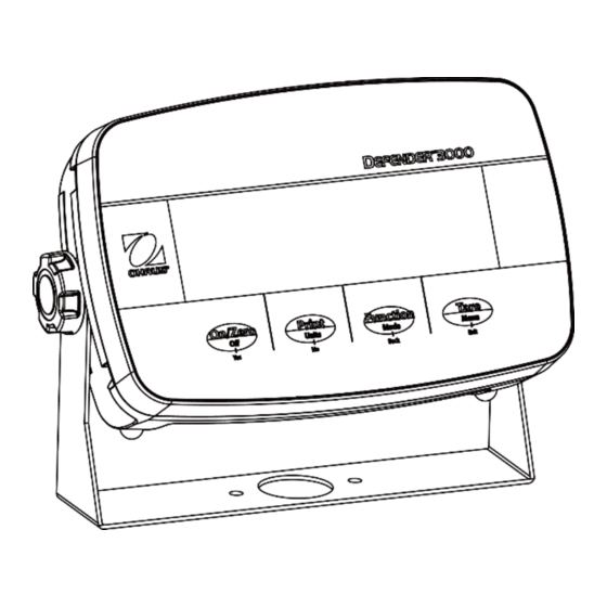
EN-4 Defender 3000 Indicators 1.3. Overview of Parts and Controls Figure 1-1 i-DT33P Indicator Item Description Item Description Front Housing Battery Cover Control Panel Mounting Bracket Rear Housing Power Cord Connector Screws (5) RS232 Connector Adjusting Knobs (2) Load Cell Connector Figure 1-2 i-DT33XW Indicator Item Description... -
Page 7: Mainboard
Defender 3000 Indicators EN-5 Mainboard 1.4. Figure 1-3 i-DT33P Mainboard Item Description Item Description DC input (J1) Display board connector (J9) Load cell terminal block (J11) Dry cell input (J2) (for models not supporting EasyConnect Load cell connector (J12) Ethernet kit / USB device kit connector (J5) (for models supporting EasyConnect Backlight connector (J10) Lead-acid battery charge board kit connector (J8) -
Page 8: Control Functions
EN-6 Defender 3000 Indicators 1.5. Control Functions Figure 1-5 i-DT33P Control Panel Figure 1-6 i-DT33XW Control Panel Button Primary Function On/Zero Print Function Tare (Short Press) If the terminal is Sends the current Initiates an Performs a tare off, press to power value to the RS232 application mode. - Page 9 Defender 3000 Indicators EN-7 Figure 1-7 Display Item Description Item Description NET symbol Pound, Ounce, Pound:Ounce symbols Center of Zero symbol Kilogram, Gram symbols Stable weight symbol Pieces symbol Negative symbol Percent symbol, Tonne symbol Preset tare symbol Battery symbol Totalization symbol...
-
Page 10: Installation
Use 6 C size dry batteries (not included). In some regions, the i-DT33P model comes with one lead-acid battery installed by factory. Note: You can contact an authorized OHAUS dealer to buy the lead-acid battery as an option. i-DT33XW This model comes with one lead-acid battery installed by factory default. -
Page 11: Internal Connections
Defender 3000 Indicators EN-9 Internal Connections Some internal connections require to open the housing first. Therefore, please check the Open the Housing section below before making connections. CAUTION: ELECTRICAL SHOCK HAZARD. REMOVE ALL POWER CONNECTIONS TO THE INDICATOR BEFORE SERVICING OR MAKING INTERNAL CONNECTIONS. THE HOUSING SHOULD ONLY BE OPENED BY AUTHORIZED AND QUALIFIED PERSONNEL, SUCH AS AN ELECTRICAL TECHNICIAN. - Page 12 Note: If your indicator does not contain the lead-acid battery but you want to purchase it as an accessory, you can contact an authorized OHAUS dealer to obtain it. Remove the battery cover in the direction of the arrow.
- Page 13 Defender 3000 Indicators EN-11 Remove the two screws on the charging board (circled) and take it out. Remove the five screws (circled) from the rear housing. Open the rear housing. Close the rear housing, retighten the screws and re-install the lead-acid battery after finishing internal connections Note: The screws should be tightened to 1 N•m (8-9 in-lb) torque.
- Page 14 EN-12 Defender 3000 Indicators 2.3.1.3 i-DT33XW Turn the two knobs (circled) on each side of the indicator to disassemble the bracket. Remove the six hex head bolts from the rear housing of the indicator. Open the rear housing. Close the housing and re-install the bolts after finishing internal connections Note: The bolts should be tightened to 2.5 N•m (20-25 in-lb) torque to ensure a watertight seal.
-
Page 15: Easyconnect Tm Indicator
Figure 2-2 i-DT33XW Note: For connecting bases which do not support EasyConnect to an EasyConnect indicator, contact an authorized OHAUS dealer to obtain a load cell cable gland kit (P/N 30379716) as an accessory. 2.3.3 Non-EasyConnect Indicator To connect a non-EasyConnect... - Page 16 EN-14 Defender 3000 Indicators Connect all the cables on the load cell cable to the load cell terminal block on the mainboard (circled). Please refer to the Load Cell Terminal Block section for details of the connections. 2.3.3.2 i-DT33XW After opening the housing, unplug the battery connectors (circled) and take out the battery.
- Page 17 Defender 3000 Indicators EN-15 Unscrew the two screws on the sealing cover (circled), take out the cover, and then take out the first layer of the built-in housing. Release the load cell connector (circled) on the bottom of the indicator and then pass the load cell cable through it.
- Page 18 EN-16 Defender 3000 Indicators 2.3.3.3 Load Cell Terminal Block Proceed with the previous section, to connect the load cell terminal block, first locate it on the mainboard following the instruction in the previous two sections for the two models. After finding the load cell terminal block, check table 2-1 for the definition of each terminal screw connection and make connections based on it.
-
Page 19: I-Dt33P Rs232 Connection
Defender 3000 Indicators EN-17 2.3.4 i-DT33P RS232 Connection Connect the optional RS232 cable to the RS232 connector on the rear housing of the i-DT33P indicator. Please refer to table 2-2 for the definition of each pin if needed. Table 2-2 RS232 Pins Connection RS232 Connector Figure 2-5 i-DT33P RS232 Connector... -
Page 20: Mounting Bracket
EN-18 Defender 3000 Indicators Mounting Bracket Attach the bracket to a wall or table using fasteners (not supplied) that are appropriate for the type of mounting surface. The bracket will accommodate up to 6 mm (1/4”) diameter screws. Locate the mounting holes as shown in Figure 2-7 and 2-8. -
Page 21: Operation
Defender 3000 Indicators EN-19 3. OPERATION Turning the Scale On/Off To turn the scale on, short press the On/Zero Off button. The scale performs a display test, momentarily displays the software version, the GEO value and then enters the last active weighing mode. LFt ON Note: If the hardware lock switch is enabled, will also be displayed briefly. -
Page 22: Counting Mode
EN-20 Defender 3000 Indicators Counting Mode Use this application to count the number of pieces on the pan based on an Average Piece Weight (APW). 3.3.1 Enter the Mode COUNt Press and hold the Mode button until is displayed. CLr.PwW When the Mode button is released, the display shows ... -
Page 23: Check
Defender 3000 Indicators EN-21 Check Use this application to compare the weight of items to a target weight range. The display color will change according to the comparing result: Red indicates over the target weight range Green indicates within the target weight range. ... - Page 24 EN-22 Defender 3000 Indicators The Check configurations are defined below (defaults in Bold). Item Available Settings Comments CHECK Check ( ) On, Off To enable or disable Check Note: You cannot disable Check if you are in the mode currently.
-
Page 25: Totalization
Defender 3000 Indicators EN-23 Totalization Use this application to manually or automatically accumulate the multiple weights. Statistical data (the number of samples, the total weight, the average weight, the minimum weight, the maximum weight and the difference in weight) is stored in memory for review and printing. 3.5.1 Application Settings There are three totalization options:... -
Page 26: Totalization Rules
EN-24 Defender 3000 Indicators 3.5.5 Totalization Rules The totalization operation will fail when: The current weight is unstable. The load's net weight is smaller than 5d. The overall totalized number is larger than 999999.(The unit is according to what you set for the scale.) The total number of totalization exceeds 9999 times. -
Page 27: Application Settings
Defender 3000 Indicators EN-25 3.5.7 Application Settings The application can be customized for user preferences. Please refer to Application Settings section in Weighing Mode for details about how to enter application settings. The Totalization Configurations are defined below (defaults in Bold). Item Available Settings Comments... -
Page 28: Menu Settings
EN-26 Defender 3000 Indicators 4. MENU SETTINGS The User Menu allows the customizing of scale settings. Note: Sub-menu for options (USB, Ethernet and Print2 in the table below) will be active only when the specific board is installed. See their separate option instruction manuals for additional setting information. Menu Navigation 4.1.1 User Menu (in segments) -
Page 29: Button Navigation
Defender 3000 Indicators EN-27 4.1.2 Button Navigation The Yes button: allows entry into the displayed menu. Accepts the displayed setting and advances to the next item. The No button: rejects entry into the displayed menu. Rejects the displayed menu and moves on to the next selection. The Back button: moves backwards to the previous menu. -
Page 30: Calibration Menu
EN-28 Defender 3000 Indicators Calibration Menu C.A.L Enter the calibration menu to perform calibrations. Initial Calibration 4.2.1 When the scale is operated for the first time, a zero and span calibration are recommended to ensure accurate weighing results. Before performing the calibration, be sure to have the appropriate calibration weights as listed in table 4-1. Ensure that the LFT switch/calibration lock is set to the unlocked position. -
Page 31: Linearity Calibration [ Lin ]
Defender 3000 Indicators EN-29 Repeat the process until all the digits are correct. Press the Yes button to accept calibration point. It is flashing on the display. Place a calibration mass of the specified weight on the pan and press the Yes button. --C-- -DONE- The display shows... -
Page 32: Calibration Test [ C.test ]
EN-30 Defender 3000 Indicators Short press the No button several times until the desired GEO number appears. Press the Yes button to accept. Note: Press the Back button can decrease the digit. C.test Then the display shows . Press the Exit button to exit. C.test 4.2.6 Calibration Test... -
Page 33: Setup Menu
Defender 3000 Indicators EN-31 Setup Menu Enter this menu S.E.t.U.P to set scale parameters. Default settings are in bold. Sub-Menu (in Menu Sub-Menu Options Options (in segment) segment) reset NO, yes Reset no, yes C.UNIt Capacity Unit kg, lb rANGE SINGLE, DUAL Range Single, Dual... - Page 34 EN-32 Defender 3000 Indicators GrAd2 Grad2 Set the second readability of the scale. Note: The value of graduation 2 must be larger than graduation 1, and it applies to capacity as well. The capacity and graduation value should be within the following range, or your setting will be unsuccessful: Capacity / 30000 ≤...
-
Page 35: Readout Menu
Defender 3000 Indicators EN-33 Readout Menu Enter this menu to set user preferences. Default settings are in bold. Sub-Menu (in Menu Sub-Menu Options Options ( in segment) segment) reset NO, yes Reset no, yes Stable 0.5d, 1d, 2d, 5d Stability 0.5d, 1d, 2d, 5d ZErO 2, 100... - Page 36 EN-34 Defender 3000 Indicators = backlight is enabled and always on. AUtO = backlight is disabled after 20 seconds of no activity. b.COLOr] Backlight Color Set the display backlight color. AmMber = backlight color is amber. Green = backlight color is green. = backlight color is red.
-
Page 37: Unit Menu
Defender 3000 Indicators EN-35 Unit Menu U.N.I.t Enter this menu to activate the desired units. Reset Gram (g) Kilogram (kg) Pound (lb) Ounce (oz) Pound:Ounce (lb:oz) Metric Tonne (t) Note: Available units vary by model. In addition, due to national laws, the indicator may not include some of the units listed. - Page 38 EN-36 Defender 3000 Indicators PArItY Parity Set the data bits and parity. 7 EVEN = 7 data bits, even parity 7 ODD = 7 data bits, odd parity 7 NONE = 7 data bits, no parity 8 NONE = 8 data bits, no parity StOP Stop bit Set the number of stop bits.
-
Page 39: Print Menu
Defender 3000 Indicators EN-37 4.6.2 Print Menu Enter this menu to set printing parameters. Default settings are bold. Sub- Options (in Menu Sub-Menu Menu (in Options segment) segment) ASSIGN DemMaN, ON.Stab, Demand, Auto On Stable, Auto On Accept, ON.ACep, INter, Assignment Interval(seconds), MT- mMt.CON, OH.CON,... - Page 40 EN-38 Defender 3000 Indicators mMt.Con MT-Continuous If MT-Continuous is selected, the print output will be in the MT-Continuous format. mMt.CON = printing occurs continuously. Note: Refer to Appendix A for MT-Continuous format. C.SUmM Off = disabled On = enabled OH.Con OH-Continuous If OH-Continuous is selected, the print output will be in the OH-Continuous format.
-
Page 41: Usb Configuration
Defender 3000 Indicators EN-39 Connect the indicator to OHAUS ScaleMate software on a PC via the RS232 (or USB or Ethernet optional ports). To customize print template, you need to go to the ScaleMate software, Select Print Template on the top bar, and then double click items in the left column to select which ones you want to put in your print template. -
Page 42: Lock Button Configuration
EN-40 Defender 3000 Indicators Lock Button Configuration L.O.C.k This menu is used to lock access to certain buttons. When you select ON for one selection, the associated button press will be ignored. If you select Lock All Keys, you will lose function of all buttons. UN.LOCK If the Menu button has been locked, long press the Menu button for 15 seconds until you see . -
Page 43: Legal For Trade
Defender 3000 Indicators EN-41 5. LEGAL FOR TRADE When the indicator is used in trade or a legally controlled application, it must be set up, verified and sealed in accordance with local weights and measures regulations. It is the responsibility of the purchaser to ensure that all pertinent legal requirements are met. -
Page 44: Sealing
Figure 5-5. i-DT33XW Wire Sealing Figure 5-6. i-DT33XW Paper Sealing For the sealing of the scale base, when the i-DT33P or i-DT33XW indicator is connected to an OHAUS Defender 3000 series base boasting EasyConnect function, it has a memory module on the load cell cable. - Page 45 Defender 3000 Indicators EN-43 When the i-DT33P or i-DT33XW indicator is connected to a base that does not include a memory module, but supports load cell adapter connection, the connection between the indicator and the base shall be sealed by using a connector cover (P/N: 30538022), sealing sticker or wire seal.
-
Page 46: Maintenance
EN-44 Defender 3000 Indicators i-DT33XW Figure 5-9. i-DT33XW Sealing ( Connecting cable with connector and memory module) Paper Wire seal seal Figure 5-10. i-DT33XW Sealing ( Connecting cable with connector and without memory module) 6. MAINTENANCE CAUTION: DISCONNECT THE UNIT FROM THE POWER SUPPLY BEFORE CLEANING. Cleaning For i-DT33P, the housing may be cleaned with a cloth dampened with a mild detergent if necessary. -
Page 47: Troubleshooting
Service assistance in the United States, call toll-free 1-800-526-0659 between 8:00 AM and 5:00 PM Eastern Standard Time. An OHAUS Product Service Specialist will be available to assist you. Outside the USA, please visit our website www.ohaus.com to locate the OHAUS office nearest you. -
Page 48: Technical Data
EN-46 Defender 3000 Indicators 7. TECHNICAL DATA Specifications Equipment Ratings: Indoor use only Altitude: 2,000m Operating temperature: -10° C to 40° C Maximum relative humidity 80% for temperatures up to 31 ° C decreasing linearly Humidity: to 50% relative humidity at 40° C. Electrical supply: 100 - 240V~, 0.5A, 50/60Hz Voltage fluctuations:... - Page 49 Defender 3000 Indicators EN-47 Model i-DT33XW Construction 304 stainless steel housing, 304 stainless steel bracket Protection IP66 Maximum displayed resolution 1:30,000 1:10,000 or 2 × 3,000e Class III @ 1 µV/e (EC, OIML) Maximum approved resolution 1:6,000 (NTEP/Measurement Canada) Class III Kilogram, Gram, Pound, Ounce, Pound: Ounce, Tonne (Metric Weighing units Tonne)
-
Page 50: Table Of Geo Code Values
EN-48 Defender 3000 Indicators Table of Geo Code Values TABLE 7-1 GEO CODES Elevation in meters 1300 1625 1950 2275 2600 2925 3250 1300 1625 1950 2275 2600 2925 3250 3575 Elevation in feet 1060 2130 3200 4260 5330 6400 7460 8530 9600... -
Page 51: Compliance
This product complies with the applicable harmonized standards of EU Directives 2011/65/EU (RoHS), 2014/30/EU (EMC), 2014/35/EU (LVD) and 2014/31/EU (NAWI). The EU Declaration of Conformity is available online at www.ohaus.com/ce. This product complies with the applicable statutory standards of the Restriction of the Use of... - Page 52 Unintentional Radiator per 47CFR Part B Trade Name: OHAUS CORPORATION Model or Family identification: Defender 3000 series Party issuing Supplier’s Declaration of Conformity: Ohaus Instruments (Changzhou) Co., Ltd. 2F, 22 Block, 538 West Hehai Road, Xinbei District, Changzhou Jiangsu 213022 China Phone: +86 519 85287270 Responsible Party –...
-
Page 53: Appendices
Table 9-1. Non-significant weight data and tare data digits are transmitted as spaces. The continuous output mode provides compatibility with OHAUS products that require real-time weight data. the standard continuous output. Table 9-1 shows the format for the standard continuous output. - Page 54 EN-52 Defender 3000 Indicators Table 9-4: Status Byte C Bit Definitions Bits 2, 1, and 0 Weight Description lb or kg, selected by Status Byte B, bit 4 grams (g) metric tons (t) ounces (oz) not used not used tons (ton) no units Bit 3 Print Request = 1...
-
Page 55: Appendixb
Defender 3000 Indicators EN-53 Appendix B MT-SICS Commands Command Function LEVEL 0 Reset the scale Inquiry of all available SICS commands Inquiry of SICS level and SICS versions Inquiry of scale data Inquiry of scale software version Inquiry of serial number Send stable weight value Send weight value immediately Send weight value repeatedly... -
Page 56: Appendixc
Commands listed in the following table will be acknowledged by the scale. The scale will return “ES” for invalid commands. Please add \r\n after each command to send.(\r refers to \return; \n refers to \newline) OHAUS Commands Command Function Print displayed weight (stable or unstable). -
Page 57: Appendixd
Defender 3000 Indicators EN-55 Appendix D OH-continuous Print Format 1: For the printout result including interval and continuous printing mode of Check Weighing application Application Weight Unit T/N/G/PT Stability Status Field (Right Space (Right Space Space (Right Space Term. (Right aligned) aligned) -
Page 58: Limited Warranty
OHAUS products are warranted against defects in materials and workmanship from the date of delivery through the duration of the warranty period. During the warranty period OHAUS will repair, or, at its option, replace any component(s) that proves to be defective at no charge, provided that the product is returned, freight prepaid, to OHAUS. - Page 60 With offices worldwide / Con oficinas en todo el mundo / Avec des bureaux partoutdans le monde / MitBürosweltweit / Con uffici in tuttoilmondo www.ohaus.com *30696592* 30696592A © 2021 Ohaus Corporation, all rights reserved / todos los derechosreservados / tousdroitsréservés / alle Rechte vorbehalten / tutti i dirittiriservati...
- Page 61 Defender 3000 Series Base Instruction Manual English Español Français...
- Page 63 Note: Not included with some models Wiring Connections When connecting the base to an OHAUS indicator equipped with the matching circular connector, push the base connector onto the indicator connector and turn the locking ring clockwise to lock it in place.
- Page 64 EN-2 Defender Series Base If your base does not support EasyConnect , please refer to the indicator's manual for how to connect load cell connector. TABLE 1. LOAD CELL CONNECTION Type1. For model i-DxxxB1R, i-DxxxB1L base FUNCTION WIRE COLOR + Excitation - Excitation Black + Signal...
- Page 65 For service assistance or technical support in the United States, call toll-free 1-800-526-0659 between 8:00 AM and 5:00 PM EST. An OHAUS product service specialist will be available to provide assistance. Outside the USA, please visit our web site, www.ohaus.com to locate the OHAUS office nearest you.
- Page 66 EN-4 Defender Series Base TABLE 2.2 SPECIFICATIONS Model i-D15C1R i-D30C1R i-D60C1R i-D60C1L i-D150C1L i-D150C1X i-D300C1X Capacity 15 kg 30 kg 60 kg 60 kg 150 kg 150 kg 300 kg Approved Resolution OIML 3000e Safe Overload Capacity 150% of capacity Pan Dimensions 305 x 355 mm 420 x 550 mm...
- Page 67 Defender Series Base EN-5 Drawings Figure 1. Defender Base Dimension Drawing. TABLE 3. DIMENSIONS Height of Pan to Base Height of Pan Pan Depth Pan Width Surface of Table i-DxxxB1R 355 mm / 14.0 in 305 mm / 12.0 in 128 mm / 5.3 in 75mm / 3.0 in i-DxxxB1L...
- Page 68 OHAUS products are warranted against defects in materials and workmanship from the date of delivery through the duration of the warranty period. During the warranty period OHAUS will repair, or, at its option, replace any component(s) that proves to be defective at no charge, provided that the product is returned, freight prepaid, to OHAUS.
- Page 69 Nota: No incluido con algunos modelos. Conexiones del cableado Al conectar la base a un indicador OHAUS equipado con el correspondiente conector circular, empuje el conector de la base en el conector del indicador y gire el anillo de bloqueo para asegurarlo.
- Page 70 ES-2 Base serie Defender Si su base no es compatible con EasyConnect , consulte el manual del indicador para saber cómo conectar el conector de la célda de carga. TABLA 1. CONEXIÓN DE LA CELDA DE CARGA Tipo1. Para el modelo i-DxxxB1R, base i-DxxxB1L FUNCIÓN COLOR DEL CABLE + Excitació...
- Page 71 Si la sección de solución de problemas no resuelve o describe su problema, póngase en contacto con su agente de servicio autorizado de OHAUS. Para asistencia de servicio o soporte técnico en los Estados Unidos llamar al número gratuito 1-800-526-0659, de 08:00 a.m. a 05:00 p.m. EST. Un especialista de servicio para productos OHAUS estará...
- Page 72 ES-4 Base serie Defender TABLA 2.2 ESPECIFICACIONES Modelo i-D15C1R i-D30C1R i-D60C1R i-D60C1L i-D150C1L i-D150C1X i-D300C1X Capacidad 15 kg 30 kg 60 kg 60 kg 150 kg 150 kg 300 kg Resolució n aprobada OIML 3000e Capacidad segura de 150 % de la capacidad sobrecarga Dimensiones del plato 305 x 355 mm...
- Page 73 Base serie Defender ES-5 TABLA 2.4 ESPECIFICACIONES Modelo i-D15C1R i-D30C1R i-D75C1R i-D75C1L i-D150C1L i-D150C1X i-D300C1X Capacidad 30 lb / 15 kg 60 lb / 30 kg 150 lb / 75 kg 150 lb / 75 kg 300 lb / 150 kg 300 lb / 150 kg 600 lb / 300 kg Resolució...
- Page 74 Los productos OHAUS están garantizados contra defectos en los materiales y mano de obra desde la fecha de entrega y hasta que termine el perí odo de garantí a. Durante el perí odo de garantí a, OHAUS reparará, o si procede, reemplazará...
- Page 75 Note: Non inclus avec certains modèles. Connexions de câblage Lors de la connexion de la base à un indicateur OHAUS équipé avec le connecteur circulaire correspondant, pousser le connecteur de base sur le connecteur d’indicateur et tourner la bague de verrouillage dans le sens horaire pour le verrouiller en place.
- Page 76 FR-2 Base de séries Defender , veuillez vous référer au manuel de l’indicateur pour savoir Si votre base ne prend pas en charge EasyConnect comment connecter le connecteur du capteur de charge. TABLEAU 1. CONNEXION DE LA CELLULE DE CHARGE Type1.
- Page 77 OHAUS Pour le service d’assistance ou le support technique aux États-Unis, appeler gratuitement le 1-800-526- 0659 entre 8:00 et 17:00 H EST. Un spécialiste de produit OHAUS sera disponible pour vous fournir une assistance. Hors des USA, veuillez visiter notre site web à l’adresse www.ohaus.com afin de localiser le bureau OHAUS le plus proche.
- Page 78 FR-4 Base de séries Defender TABLEAU 2.2 SPÉCIFICATIONS Modè le i-D15C1R i-D30C1R i-D60C1R i-D60C1L i-D150C1L i-D150C1X i-D300C1X Capacité 15 kg 30 kg 60 kg 60 kg 150 kg 150 kg 300 kg Ré solution validé e OIML 3000e Capacité de surcharge 150 % de la capacité...
- Page 79 Base de séries Defender FR-5 TABLEAU 2.4 SPÉCIFICATIONS Modè le i-D15C1R i-D30C1R i-D75C1R i-D75C1L i-D150C1L i-D150C1X i-D300C1X Capacité 30 lb / 15 kg 60 lb / 30 kg 150 lb / 75 kg 150 lb / 75 kg 300 lb / 150 kg 300 lb / 150 kg 600 lb / 300 kg Ré...
- Page 80 Kit de montage frontal i-D33 GARANTIE LIMITÉE Les produits OHAUS sont garantis contre les défaillances dans les matériels et la fabrication à partir de la date de livraison jusqu’à la couverture entière de la période de garantie. Pendant la période de garantie, OHAUS réparera gratuitement, selon son appréciation ou remplacera tous les composants défectueux, à...
- Page 84 *30708958* P/N 30708958 A © 2021 OHAUS Corporation, all rights reserved / todos los derechosreservados / tousdroitsréservés / alleRechtevorbehalten / tutti i dirittiriservati / todos os direitos reservados / Alla rättigheter förbehållna / alle rechten voorbehouden / alle rettigheder forbeholdes / wszelkie prawa zastrzeżone / všechna...
Need help?
Do you have a question about the Defender I-D33P15B1R1 and is the answer not in the manual?
Questions and answers