OHAUS i-DT33P Instruction Manual
Indicator ethernet option
Hide thumbs
Also See for i-DT33P:
- Instruction manual (64 pages) ,
- User manual (152 pages) ,
- Service manual (51 pages)
Advertisement
Quick Links
Advertisement

Subscribe to Our Youtube Channel
Related Manuals for OHAUS i-DT33P


Summary of Contents for OHAUS i-DT33P
- Page 1 / i-DT33XW Indicator Ethernet Option Instruction Manual...
-
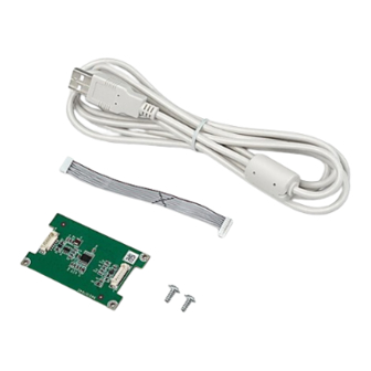
Page 3: Kit Contents
EN-1 INTRODUCTION ® This Ethernet interface kit is for use with the Defender 3000 i-DT33P and i- DT33XW indicators. CAUTION: THE INSTALLATION AND CONNECTIONS SHOULD ONLY BE PERFORMED BY AUTHORIZED AND QUALIFIED PERSONNEL, SUCH AS AN ELECTRICIAN. KIT CONTENTS ... -
Page 4: Interface Installation
WARNING: BEFORE INSTALLATION, POWER OFF THE INDICATOR AND REMOVE ALL EXTERNAL AC POWER CONNECTIONS. i-DT33P Remove the battery cover in the direction of the arrow, and take out dry batteries if used. Slightly push the end of the charging cover (circled) in the direction of the... - Page 5 EN-3 Remove the Ethernet sealing plug upwards. Take out the cable supplied. Connect one side to the main board connector (circled), and pass the other side through the side hole.
- Page 6 EN-4 Take out the Ethernet PC board supplied. Connect the cable's another side to the connector on the Ethernet board (circled). Then insert the Ethernet board into the two card slots (circled) on both sides. Ethernet PC board Take out the Ethernet cable supplied, and pass it through the hole where the sealing plug is removed, and then connect the Ethernet interface to the connector on the Ethernet board (circled).
- Page 7 EN-5 Re-install the dry batteries if used and close the battery cover to finish installation. i-DT33XW Remove the six hex head bolts from the rear housing of the indicator.
- Page 8 EN-6 Release the strain relief for option connector (circled) including the watertight seal in it on the bottom of the indicator and remove the plug at the end of it. Watertight Seal (with One Hole) Plug Take out the cable and the Ethernet PC board supplied. Connect one side of the cable to the connector on the Ethernet PC board (circled) and the other to the indicator's main board connector (circled).
- Page 9 EN-7 Pin the upper right corner of the Ethernet PC board on the positioning column (circled). Make sure the back of the Ethernet PC board is facing up. Screw the two screws (circled) on the Ethernet PC board to the indicator. Pass the Ethernet cable through the strain relief for option connector and attach the watertight seal to it, and then connect the Ethernet interface to the connector on the Ethernet board (circled).
- Page 10 EN-8 Note: If you install RS232 and the Ethernet kit at the same time, please use the supplied watertight seal with two holes. Make sure to install the RS232 cable first before the connection of Ethernet kit. Pass the RS232 cable through one hole of the watertight seal and the Ethernet cable through another.
- Page 11 EN-9 Tighten the strain relief for option connector with the watertight seal in it (circled). Close the housing and re-install the bolts to finish installation.
-
Page 12: Operation
EN-10 SETUP Upon installation, the indicator will recognize the Ethernet interface kit and add related items to the menu. Ethernet Connection If DHCP is set to be ON, the IP share or router will automatically assign IP Address. If the DHCP is set to be OFF, users need to setup the IP Address, Subnet Mask, Gateway, Primary DNS and Secondary DNS. - Page 13 EN-11 CONFIGURATION The Ethernet option board is connected to the i-DT33P and i-DT33XW indicator through the RS232 interface. The baud rate is 19200. If the option board is not connected, the submenu will not display. Reset no, yes IP Address 169.254.1.1-9761...
- Page 14 The alternative command of Print, Tare, Zero can be set to 'a' ~ 'z' or 'A' ~ 'Z'. Note: The submenu will be displayed after the installation of the Ethernet option board. To set the IP address and other parameters, you need to go to the ScaleMate software. To obtain it, contact an authorized OHAUS dealer.
- Page 16 *30696722* P/N 30696722 B © 2022 Ohaus Corporation, all rights reserved / todos los derechos reservados / tous droits ré servé s / Alle Rechte vorbehalten / Tutti i diritti riservati / 版权所有 Printed in China / Impreso en China / Imprimé en Chine / Gedruckt in China / Stampato in...
Need help?
Do you have a question about the i-DT33P and is the answer not in the manual?
Questions and answers