
Subscribe to Our Youtube Channel
Related Manuals for Mecmesin BFG 10


Summary of Contents for Mecmesin BFG 10
- Page 1 Published on Mecmesin Support (https://help.mecmesin.com) Home > Basic Force Gauge (BFG) Operating Manual Support Product Revision ID Manual 431-221-05-L00...
- Page 2 Introduction Before Use Operation Maintenance Powering the Gauge 4.1.1 Fitting the rechargeable batteries 4.1.2 Charging the rechargeable batteries 4.1.3 Low battery symbol 4.1.4 Mains operation 4.1.5 Fitting of alkaline batteries 4.1.6 Battery safety information Using the Gauge 4.2.1 Fitting accessories 4.2.2 Mounting to a test stand 4.2.3...
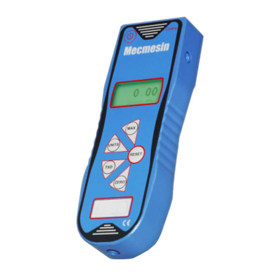
- Page 3 The Mecmesin BFG is a member of a series of highly versatile display units. By using the latest integrated circuit technology it has been possible to produce an instrument which can be used to measure tensile and compressive...
-
Page 4: Before Use
Before Use Upon receiving the unit please check that no physical damage has occurred to the packaging material, plastic case or the instrument itself. If any damage is evident please notify Mecmesin immediately. -
Page 5: Operation
Operation The most commonly used features such as displaying force, peak hold, zero and changing of displayed units can all be done by pressing a single dedicated key on the front panel. For less frequently used features a number of “hot keys” are provided, whereby the operator simply presses and holds 2 keys to enable a gauge option. -
Page 6: Maintenance
Short circuit Heat or incinerate Disassemble or deform cells Use alternative chargers other than those supplied by Mecmesin Use replacement parts other than those supplied by Mecmesin Immerse in water Solder anything to the battery terminals Reverse individual cell polarity Using the Gauge 4.2.1... -
Page 7: Mounting To A Test Stand
Mecmesin test stand. Each Mecmesin test stand is supplied with a dedicated ‘dovetailed mounting bracket’ and screws for this purpose. If you wish to mount the gauge to another type of stand, ensure that the screws used are threaded into the gauge to a maximum depth of 10mm maximum depth of 10mm. - Page 8 Should the instrument have sustained a catastrophic overload, the symbol ‘OL’ will be permanently displayed and the instrument must be returned to Mecmesin or an approved Mecmesin distributor for repair. Forces greater than 120% of full-scale will produce an OL symbol which will remain on the display all the time the overload is present.
-
Page 9: Display Of Tension/Compression
key. 4.2.4 Display of Tension/Compression Tensile forces are displayed on the BFG and recognised by the symbol See Fig 2. Compressive forces are displayed on the BFG and recognised by the symbol... - Page 10 See Fig 3b. 4.2.5 Zeroing the Gauge During the operation of the gauge it is often necessary to zero the display - e.g. when you wish to tare out the weight of a grip, so it does not become part of the measured reading. Press and release the ZERO ZERO key.
-
Page 11: Max Compression
4.2.8 Max Tension Press the MAX MAX key and the display will show the maximum tensile force identified by the symbol. 4.2.9 Max Compression Press the MAX MAX key again and the display will show the maximum compressive force identified by the... -
Page 12: Normal Mode
symbol. 4.2.10 “Normal” mode Press the MAX MAX key again and the display will show the current load applied to the loadcell in either direction, maintaining a “running” display. -
Page 13: Data Output
Press the RESET RESET key to clear both maximum registers and prepare for detecting the next maximum readings. 4.2.11 Data Output The BFG has RS232, Mitutoyo and analogue output signals. It is possible to transmit the displayed reading to peripheral devices (e.g. PC, printer) by pressing and releasing the TXD TXD key. -
Page 14: Display Messages
An overload is registered when the load exceeds 120% of the rated capacity. Removing recorded overloads can only be undertaken by Mecmesin or an approved Mecmesin distributor. 4.3.5... - Page 15 Eeprom error - Memory read error ‘Err 81’ Error code 1 - Processor reset error If a ‘memory read error’ or ‘processor reset error’ is displayed please contact Mecmesin or an authorised representative to arrange for the BFG to be repaired. Dimensions (in Millimetres)
- Page 16 Rear View...
-
Page 17: Range & Resolution
Allocation for the pins on the female 15 way ‘D Type’ Communication Connector. BFG Specification Table 4.5.1 Range & Resolution Model no: Model no: 2.2 x BFG 10 BFG 10 10,000 x 2 10 x 0.002- 1,000 x 0.2 35 x 0.01 0.0002 0.0005... - Page 18 Spring Copse Business Park Slinfold, West Sussex RH13 0SZ United Kingdom Mecmesin Ltd is a company registered in England and Wales, company number 01302639. PPT Holdings Company Source URL (modified on 20/06/2019 - Source URL (modified on 20/06/2019 - 14:01):...
Need help?
Do you have a question about the BFG 10 and is the answer not in the manual?
Questions and answers