Advertisement
Advertisement

Related Manuals for Mecmesin AFG Series


Summary of Contents for Mecmesin AFG Series
-
Page 3: Table Of Contents
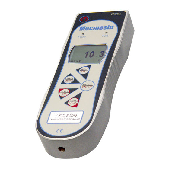
The Mecmesin AFG is the flagship member of a series of highly versatile display units. By using the latest integrated circuit technology it has been possible to produce an instrument which can be used to measure tensile and compressive forces accurately, whilst being simple to use by the operator. -
Page 4: Powering The Gauge
POWERING THE GAUGE The AFG is supplied with a set of 5 Nickel Metal Hydride AAA rechargeable batteries. For safety reasons during transportation the batteries are shipped discharged. To obtain maximum battery life we recommend that you charge them with the charger/adaptor supplied for at least 14 - 16 hours when you first receive the AFG. -
Page 5: Using The Gauge
M6 male thread. On the rear of the gauge there are two M5 threaded holes, Mounting to a test stand which can be used for mounting the gauge to a Mecmesin test stand. Each Mecmesin test stand is supplied with a dedicated ‘dovetailed mounting bracket’... - Page 6 Should the instrument have sustained a catastrophic overload, the symbol OL will be permanently displayed and the instrument must be returned to Mecmesin or an approved Mecmesin distributor for repair. To power down the gauge press the red key.
-
Page 7: Basic Functions
Basic Functions Display of Tension/ Tensile forces are displayed on the AFG and recognised by Compression the symbol (See Fig. 2a) Compressive forces are displayed on the AFG and recognised by the symbol (See Fig. 2b) If the AFG has suffered a serious Fig. - Page 8 Zeroing the Gauge During the operation of the gauge it is often necessary to zero the display – e.g. when you wish to tare out the weight of a grip, so it does not become part of the measured reading. Press and release the ZERO key. The display will blink momentarily as the zero operation is carried out.
- Page 9 Fig. 3a Dual Max Max tension reading Max compression reading Load currently applied to load cell Max Tension Press the MAX key again and the display will show the maximum tensile force identified by the symbol. (See Fig. Fig. 3b Max tension reading Max Compression...
- Page 10 "Normal" mode Press the MAX key again and the word MAX has now disappeared from the display. The display will now indicate forces applied in both directions as they are applied to the transducer and maintain a "running" display. Press the RESET key to clear both maximum registers and prepare for detecting the next maximum readings.
-
Page 11: Optional Settings
Remote key press from PC Hold down the Ctrl key on the PC keyboard and press; a to simulate pressing the TXD key * b to simulate pressing the UNITS key c to simulate pressing the MAX key d to simulate pressing the RESET key e to simulate pressing the ZERO key * Note that the continuous transmission mode cannot be entered via these methods. -
Page 12: Additional Force & Torque Sensors
Torque Sensors All Advanced Force Gauges have a 15-pin ‘Smart’ connector ‘Smart’ sensors port on the left-hand side for interface with Mecmesin external Warning! The AFG must be ‘Smart’ force and torque sensors. This allows you to use your powered down when connecting... -
Page 13: Advanced Menu Options
Advanced Menu Options All the features and advanced menu options of the AFG are also applicable whilst using the ‘Smart’ range of peripheral devices. (Except for the footswitch 2 option which has the same pin requirement) The AFG Advanced Menus are accessed using the red text Navigating the menus on the keys. - Page 14 ALARM sub-menu 1 The display will show ALARM OFF and SET. Press the ENTER key to change ALARM OFF to ALARM ON. Press the DOWN key to move the arrow cursor to SET and press the ENTER key. ALARM sub-menu 2 The display will now show the two limits LIMIT 1 (lower limit) and LIMIT 2 (upper limit) plus the value they are set to and whether they are in tension (TENS’N) or compression...
- Page 15 OUT BAND - Any value falling outside the set limits LIMIT 1 and LIMIT 2 IN BAND - Any value falling between the set limits LIMIT 1 and LIMIT 2 Use the UP and DOWN keys to move the cursor and press ENTER key to select the desired feature.
- Page 16 ALARM on break Display is showing sub-menu 1 again (= ALARM ON and SET). Press ESC key to return to main-menu and again to return to main display. The main display will now show an alarm ‘bell’ symbol indicating the alarm is turned on - See Figure 7.
- Page 17 Example 1 Settings: - BOTH LED and audio alarms are active Alarm triggers on OUT BAND Alarm is set to FAIL % DROP is 10% of full- scale (e.g. AFG 100N must register drop of 10N) Main display is set to 1st peak tension screen Example 2 Settings: -...
- Page 18 Example 3 Settings: - BOTH LED and audio alarms are active Alarm triggers on OUT BAND Alarm is set to FAIL % DROP is 10% of full-scale (e.g. AFG 100N must register drop of 10N) Main display is set to 1st peak tension screen Example 4 Settings: -...
- Page 19 Example 5 Settings: - BOTH LED and audio alarms are active Alarm triggers on OUT BAND Alarm is set to FAIL % DROP is 10% of full- scale (e.g. AFG 100N must register drop of 10N) Main display is set to 1st peak tension screen (Programmable Limit For PLC applications, this function requires an external cable...
- Page 20 Press ESC key to return to main-menu page 1. The AFG may be used to send a signal to control the STAND Mecmesin range of motorised test stands via a dedicated cable. Contact your supplier for stand To configure the signal output from the AFG, press and hold interface cable the MENU key until page 1 of the main-menu appears.
- Page 21 STAND sub-menu 1 The display will show:- STAND OFF/ON -Indicates status of stand control function. REVERSE - Reverses the stand direction of travel at sample break (BREAK) or load-limit value (LIMIT). The test stand will reverse back to the start position as defined by the physical Microswitch.
- Page 22 Select BREAK or LIMIT as per Reverse sub-menu 2 (above) STOP sub-menu 1 and SET the appropriate value at which you require the test stand to stop. Select and SET UPPER load-limit, LOWER load-limit and the CYCLE sub-menu 1 number of CYCLES you wish to perform (range = 2 - 9999). Only used in conjunction with Start the test by pushing the UP or DOWN switch on your test VersaTest motorised test stand...
- Page 23 % DROP 1st Peak facility – this is used to detect the force at which a sample breaks but is not necessarily the maximum force (e.g. detecting the force at which a tablet first begins to crack.) When this feature is set to ON, two additional functions can be selected using the MAX key from the main display.
- Page 24 % DROP sub-menu 1 The display will show % DROP OFF and SET. Press the ENTER key to change % DROP OFF to % DROP ON. Press DOWN key to move the arrow cursor to SET % and press ENTER key. % DROP sub-menu 2 To determine what precisely is considered a break, you must define the % drop of full-scale value from the peak load...
- Page 25 AVERAGE/TIME x Peak 100N Average Start Threshold Stop Threshold TIME This function allows the average load reading to be displayed. The average starts being calculated when the START threshold (% of full-scale) is reached and stops being calculated when the load passes through the STOP threshold. To set AVERAGE over TIME, press and hold the MENU key until page 1 of the main-menu appears.
- Page 26 Use UP and DOWN keys to change the value, press and hold to scroll values. When the correct value is reached press ENTER key to set START. Repeat procedure for STOP. The display will revert back to AVERAGE/TIME sub-menu 1 and AV/TIME ON will now be displayed.
- Page 27 FOOTSWITCH 1 The AFG has two footswitch input pins on the 15-way D connector. This allows the footswitch to be assigned to replicate one of each of the six main key functions,ON/OFF MAX, UNITS, TXD, ZERO and RESET. This feature is useful when integrating the AFG into test or production systems.
-
Page 28: Afg Specifications
PORT - Communicates with peripheral device. Transmission of the displayed load reading can be set to include unit of measurement (UNITS ON or OFF) and BAUD rate can also be set. STORE MEM - Stores a single load reading to the internal memory. - Page 29 Port sub-menu 4 Transmission of the displayed load reading can now be set to include NULL (nothing), CR, LF or CR LF. Use the UP or DOWN key to position the arrow cursor at the desired setting. Press ENTER to select. Port sub-menu 5 A LINE DELAY, if any, to be executed after each reading is sent, can now be set.
- Page 30 x/CONSTANT A constant multiplier of from 0.001 to 10.000 can be set for a selectable base unit. Units will be replaced with an X on the main display, and the UNITS key will have no effect on the displayed units. To set X CONSTANT, first use UP and DOWN keys to move the cursor arrow to X CONSTANT on page 2 of the main- menu and press the ENTER key.
- Page 31 Fig. 12 Press and hold the ESC key until you return to page 2 of main-menu. CONTRAST The contrast of the display may be increased and decreased in this menu. From page 2 of main-menu press UP or DOWN keys to position the arrow key on CONTRAST.
- Page 32 AFG SPECIFICATIONS RANGE & RESOLUTION M M o o d d e e l l n n o o : : m m N N k k N N g g f f k k g g f f o o z z f f l l b b f f AFG2.5 2,500 x 0.5...
- Page 33 Charger output plug: Centre = positive Outer = negative If you have any feedback regarding Mecmesin, its products and services, which you would like to share with us, please contact us at f f e e e e d d b b a a c c k k @ @ m m e e c c m m e e s s i i n n . . c c o o m m...
- Page 34 Advanced Menu Options Flow Chart Page 1 On the following pages are flowcharts to help you navigate the menus found in the AFG. They appear in the order they appear on the two pages of the main menu on the Gauge. Alarm press Press UP or DOWN...
- Page 35 Advanced Menu Options Flow Chart Page 1 page 33...
- Page 36 Advanced Menu Options Flow Chart Page 1 Freeze press ALARM FREEZE OFF STAND press press FREEZE ENTER ENTER % DROP AVERAGE/TIME RATE Page 1 % Drop press ALARM % DROP OFF SET % STAND FREEZE press press press % DROP ENTER ENTER ENTER...
- Page 37 Advanced Menu Options Flow Chart Page 2 Footswitch1 Press DOWN key to press FOOTSWITCH1 FOOTSWITCH1 highlight choice. Press ENTER FOOTSWITCH2 ENTER to accept it press COMMS X CONSTANT UNITS INFORMATION CALIBRATION ZERO CONTRAST RESET Page 2 Footswitch2 Press DOWN key to press FOOTSWITCH1 FOOTSWITCH2...
- Page 38 Advanced Menu Options Flow Chart Page 2 Constant Press DOWN key to Press UP or DOWN select from choices. Once choice to increase or FOOTSWITCH1 X CONST OFF is made, PLC decrease value FOOTSWITCH2 is turned ON COMMS 00000.1 press press press X CONSTANT...
- Page 39 22.5 = 5/16”UNC COMMUNICATION (2500N MODEL) CONNECTOR Shown with Dovetail Mounting Bracket Rear View (supplied with Mecmesin Test Stands) AFG Mk 4 D Connector Pin Out: BATTERY COVER Analogue Output RS232 Transmit RS232 Receive Mitutoyo Clock Output Mitutoyo Ready Output...
- Page 40 DataPlot WINDOWS SOFTWARE FOR LOGGING, PLOTTING AND ANALYSING FORCE/TORQUE DATA DataPlot enables a PC to communicate with Mecmesin digital force gauges, torque gauges and display units, by means of the bi- directional RS232 interface which is a standard feature of all instruments. The PC functions as a...
- Page 41 page 39...
- Page 42 MultiTest The MultiTest 1 is a budget-priced, potentiometer- controlled test stand with 1000 newton capacity. When used with a Mecmesin force gauge and appropriate fixtures this system is ideal for relatively straightforward testing applications; the force gauge captures maximum tensile and compressive loads.
- Page 43 However, a Vortex- will enable complete control of the test procedure, analysis and reporting by using a new torque version of Mecmesin’s powerful, flexible and user-friendly Emperor software. Interface Cables BFG to RS232 9-way for PC, dataloggers - part no: 351-054...
- Page 44 Newton House Spring Copse Business Park Slinfold West Sussex RH13 0SZ England General Enquiries: +44 (0) 1403 799979 +44 (0) 1403 799975 Service & Calibration +44 (0) 1403 799920 +44 (0) 1403 799925 www.mecmesin.com info@mecmesin.com...
Need help?
Do you have a question about the AFG Series and is the answer not in the manual?
Questions and answers