
Related Manuals for Mecmesin AFG 2.5


Summary of Contents for Mecmesin AFG 2.5
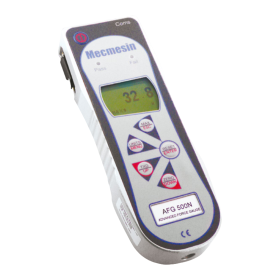
- Page 1 t e s t i n g t o p e r f e c t i o n Advanced Force Gauge Operating Manual (Includes AFTI display)
-
Page 2: Table Of Contents
Contents The Advanced Force Gauge (AFG) Powering the Gauge Using the Gauge Basic Functions Smart Force & Torque Sensors Advanced Menu Options RS232 Commands Advanced Menu Options Flowcharts Dimensions AFG Specifications page 1... - Page 3 The Mecmesin AFG is the flagship member of a series of highly versatile display units. By using the latest integrated circuit technology it has been possible to produce an instrument which can be used to measure tensile and compressive forces accurately, whilst being simple to use by the operator.
-
Page 4: Powering The Gauge
The AFG is supplied with a set of 5 Nickel Metal Powering the Hydride AAA rechargeable batteries, which are supplied Gauge fully charged to allow use straight from the box. Do not use any other battery charger other than that supplied with the force gauge. -
Page 5: Using The Gauge
10-32UNF male thread (10-500N), 5/16”UNC (1000-2500N). On the rear of the gauge there are two M5 threaded holes, which can be used for mounting the gauge to a Mecmesin test stand. Each Mecmesin test stand is supplied with a dedicated ‘dovetailed mounting bracket’... - Page 6 If you wish to mount to another type of stand, ensure that the screws used are threaded into the gauge to a maximum depth of 12mm. If screws are fitted beyond this depth, damage to the internal PCB or loadcell may occur.
-
Page 7: Basic Functions
Forces greater than 150% of full-scale will produce an audible beep until load is released and an OL symbol will appear permanently on the display. If this should occur consult your supplier to arrange inspection and repair, if necessary. To power down the gauge press the key. - Page 8 Fig. 3b Unit of measurement Symbol for compression Load indicator During the operation of the gauge it is often necessary to zero the display - e.g. when you wish it to tare out Zeroing the gauge the weight of a grip, so it does not become part of the measured reading.
- Page 9 Fig. 4a Max tension Dual Max reading Max compression reading Load currently applied to load cell Press the MAX key again and the display will show the maximum tensile force identified by the symbol. (see Max Tension Fig. 4b) Fig. 4b Max tension reading Press the MAX key again and the display will show...
- Page 10 Press the MAX key again and the word MAX has now disappeared from the display. The display will now “Normal” mode indicate forces applied in both directions as they are applied to the loadcell and maintain a “running” display. Press the RESET key to clear both maximum registers and prepare for detecting the next maximum readings.
-
Page 11: Smart Force & Torque Sensors
Torque Sensors All Advanced Force Gauges have a 15-pin ‘Smart’ connector port on the left-hand side for interface with Mecmesin external ‘Smart’ force and torque sensors. ‘Smart’ sensors This allows you to use your existing AFG to perform additional tests without the need for a dedicated Warning! The AFG must be instrument. -
Page 12: Advanced Menu Options
Main menu page 1 Stand The AFG may be used to send a signal to control the Mecmesin range of motorised test stands via a dedicated cable. Contact your supplier for stand To configure the signal output from the AFG, press... - Page 13 The display will show: STAND sub-menu 1 STAND OFF/ON indicates status of stand control function. REVERSE Reverses the stand direction of travel at sample break (BREAK) or load-limit value (LIMIT). The test stand will reverse back to the start position as defined by the physical Microswitch.
- Page 14 The display will show: STOP sub-menu 2 BREAK Sets the gauge to stop at sample break. Press ENTER to select. LIMIT Sets the load-limit value to trigger the stand stop function. Press ENTER to select. Set % of loadcell capacity to indicate the value by which BREAK sub-menu 1 the load must fall to determine a break.
- Page 15 Note: a) It is assumed that starting a test in the UP direction applies a tension force, and in the DOWN direction a compression force is applied. b) The total number of cycles must be completed, e.g. if a sample breaks during the test, the AFG will try to continue applying load for the set number of cycles.
- Page 16 The display will now show the two limits - LIMIT 1 (lower ALARM sub-menu 3 limit) and LIMIT 2 (upper limit) - plus the value they are (ALARM LIMITS) set to and whether they are in tension (TENS ’ N) or compression (COMP ’...
- Page 17 The display shows OUT BAND and IN BAND. This menu ALARM sub-menu 5 selects which values are to be considered. (ALARM BAND) OUT BAND Any value falling outside the set limits LIMIT 1 and LIMIT 2. IN BAND Any value falling between the set limits LIMIT 1 and LIMIT 2.
- Page 18 This feature is only activated when the % DROP feature Alarm on break is used in conjunction with the ALARM function. The AFG looks for a percentage (of full-scale) drop from peak load value, set in the % 1st PEAK menu (see page 23).
- Page 19 Example 2 Settings: BOTH LED and audio alarms are active Alarm triggers on OUT BAND Alarm is set to FAIL % 1st PEAK is 10% of full-scale (e.g. AFG 100N must register drop of 10N) Main display is set to 1st peak tension screen Example 3 Settings:...
- Page 20 Example 4 Settings: BOTH LED and audio alarms are active Alarm triggers on OUT BAND Alarm is set to FAIL % 1st PEAK is 10% of full-scale (e.g. AFG 100N must register drop of 10N) Main display is set to 1st peak tension screen Example 5 Settings:...
- Page 21 For PLC applications, this function requires an external cable with a built-in solid-state relay - see Specifications (Programmable Logic on pages 54-56 for details of the signal. Controller) To configure the signal output of the AFG, press and hold the MENU key until page 1 of the main menu appears.
- Page 22 The display will show SET and a default load limit at AT LIMITS sub-menu 2 which the output signal will trigger. To set the required load limit use UP and DOWN keys to adjust the value and the ENTER key to confirm the selection. The display will show STATE: AT ALARM sub-menu 1 HIGH...
- Page 23 If the PASSWORD function has been enabled, and the MENU key is held down to access the menu pages from the main display, a screen showing 0000 will appear, and the menu password ‘6284’ must be entered to proceed. Use the UP and DOWN keys to select the first number, followed by ENTER to move on to the next number, and so on.
- Page 24 When testing samples, the AFG enables the value at % 1st PEAK both the first peak and second peak to be measured and displayed. Once calculated, either result or both can be transmitted to a peripheral device (see Comms on page 28).
- Page 25 When setting up the AFG, a graphical representation of the Fig. 10 2nd peak test provides a clear insight into the % drop factor required. Direction of Please contact Mecmesin or your force approved supplier for details on Dataplot graphical charting peak software. Unit of...
- Page 26 AV/TIME x Peak 100N Average Start Threshold Stop Threshold TIME This function allows the average load reading to be displayed. The average starts being calculated when the The maximum duration of AV/ START threshold (% of full-scale) is reached and stops TIME calculation is approx.
- Page 27 To disable the AV/TIME function, press the ENTER key when the cursor arrow is aligned with ON in AV/TIME sub-menu 1. It will now display OFF. Press the ESC key to return to the main menu page 1, and again to return to the main display. The maximum duration of AV/TIME calculation is approx.
- Page 28 The AFG has two footswitch input pins on the 15-way FOOTSWITCH 1 D connector. This allows the footswitch to be assigned to replicate one of each of the five main key functions, MAX, UNITS, TXD, ZERO and RESET. This feature is useful when integrating the AFG into test or production systems.
- Page 29 Communications settings are selected to configure COMMS interfacing of the AFG with peripheral devices. The menu is also used to configure the storage settings of the AFG, which may store up to 500 readings in its on-board memory. To access the COMMS settings, press and hold the MENU key until page 1 of the main menu appears.
- Page 30 The transmission (or Baud) rate can now be set. PORT sub-menu 3 Use the UP or DOWN key to position the arrow cursor (BAUD RATE) at the relevant speed (9600, 19200, 57600 or 115200). Press ENTER to select. Additional characters can be appended to the PORT sub-menu 4 transmitted load (RS232 only).
- Page 31 To set SEND MEM, move the arrow cursor against it in SEND FROM MEMORY COMMS sub-menu 1 and press the ENTER key. This will cause a TX symbol to flash in the main display as the memory data is now transmitted to a peripheral device. The data is transmitted at the settings defined by PORT.
- Page 32 If you suspect that your AFG has sustained an Calibration overload, it is possible to check the status of the AFG immediately. Symptoms of overload may be (a) OL in display (b) buzzer sound (c) load indicator bar present even under An instrument showing an zero load.
- Page 33 Press the ESC key to return to the main menu page 2, and again to return to the main display. x CONSTANT A constant multiplier from 0.001 to 10.000 can be set for a selectable base unit. Units will be replaced with an X on the main display and the UNITS key will have no effect on the displayed units.
- Page 34 Once the desired Max display mode has been selected, MAX LOCK it is possible to lock the mode, so that further pressing the MAX key results in no change. To access the MAX LOCK function, press and hold the MENU key until page 1 of the main-menu appears. Press and release the MENU key twice to access the main menu page 3.
- Page 35 It is possible to activate a backlight on the AFG display. BACKLIGHT To access the BACKLIGHT function, press and hold the MENU key until page 1 of the main-menu appears. Press and release the MENU key twice to access the main menu page 3.
- Page 36 For hand-held tension applications it is often desirable INVERT to reverse the display, so the operator can read it more comfortably. To access the INVERT function, press and hold the Note: The menu pages are MENU key until page 1 of the main-menu appears. Press not inverted when the INVERT and release the MENU key twice to access the main function is enabled.
- Page 37 Factory Default Settings Menu Function Default Setting STAND ALARM PASSWORD FREEZE % 1st PEAK AV TIME RATE MEDIUM FOOTSWITCH1 FOOTSWITCH2 COMMS PORT SELECTED UNITS OFF SIGN ON BAUD 9600 TERMINAL CR AND LF LINE DELAY 0 SECONDS TX THRESHOLD 2% TX METHOD RS232 x CONSTANT MAX LOCK...
-
Page 38: Rs232 Commands
RS232 Commands Table: Configuration It is possible to remotely read/configure the settings of your AFG by sending the following RS232 command characters: Character in Decimal Hexadecimal Function ASCII 0x4D Current mode 0x55 Current units 0x43 Loadcell capacity 0x40 Configuration status request 0x2A Continuous transmit 0x72... - Page 39 Command: C The loadcell size in N (or N.m for torque). Note: ‘xxxx’ will be transmitted if the loadcell is not calibrated, or has a serious fault. Contact Mecmesin or your supplier. page 38...
- Page 40 Command: @ When all options are OFF, and the AFG is set at defaults, you will receive the following information listing: RESPONSE EXPLANATION OF RESPONSE Gauge type 10.000 Loadcell size in N as per transmitting ‘C’ Version number Normal Mode of operation as per transmitting ‘M’ Units of operation as per transmitting ‘U’...
- Page 41 When all options are ON, you will receive the following information listing for each option: STAND ON options explained below: STAND ON, R, 1, 2, 3 Reverse U = Up, D = Down B = Break, L = Limit Break percent or Limit Value STAND ON, S, 1, 2 Stop B = Break, L = Limit...
- Page 42 PLC OUTPUT ON options explained below: PLC OUTPUT ON, L, 1, 2 At limits R = Reset, C = Continuous, P = Pulse Limit value PLC OUTPUT ON, A, 1 At alarm H = High, L = Low PASSWORD 1 options explained below: PASSWORD 1 Menu Password ON or OFF FREEZE ON options explained below:...
- Page 43 RATE 1 ON options explained below: RATE 1 M = Medium, H = High FOOTSWITCH1 ON options explained below: FOOTSWITCH1 ON, 1 Footswitch 1 - M = Max, U = Units, T = Txd, Z = Zero, R = Reset FOOTSWITCH2 ON options explained below: FOOTSWITCH2 ON, 1 Footswitch 2 - M = Max, U = Units, T = Txd, Z = Zero, R = Reset...
- Page 44 MAX LOCK 1 options explained below: MAX LOCK 1 Max key locked, ON or OFF UNIT LOCK 1 options explained below: UNITS LOCK 1 Units key locked, ON or OFF BACKLIGHT 1 options explained below: BACKLIGHT 1 Backlight enabled, ON or OFF AUTO-OFF 1 options explained below: AUTO-OFF 1 Auto-off time, OFF, 5 mins or 10 mins...
-
Page 45: Advanced Menu Options Flowcharts
Options avancées du Menu - Schéma Menu Page 1 Sur les pages suivantes, une série d’organigrammes vous permettra de naviguer dans les menus avancés de l’AFG. Ces schémas suivent un affichage chronologique à partir du menu principal du dynamomètre. STAND page 44... - Page 46 Options avancées du Menu - Schéma Menu Page 1 ALARM page 45...
- Page 47 Options avancées du Menu - Schéma Menu Page 1 press press ENTER PLC OUTPUT RESET 12.75 STAND ALARM CONTINUOUS press press PASSWORD ENTER ENTER press AT LIMITS PULSE FREEZE ENTER % 1ST PEAK press ENTER AT ALARM AVERAGE/TIME Page 1 STATE HIGH press...
- Page 48 Options avancées du Menu - Schéma Menu Page 2 FREEZE press FREEZE DISP STAND ALARM press press ENTER PASSWORD ENTER FREEZE % 1ST PEAK HIGH AVERAGE/TIME Page 1 % 1ST PEAK press SET % % DROP TX 1st PEAK STAND ALARM TX 2nd PEAK PASSWORD...
- Page 49 Options avancées du Menu - Schéma Menu Page 2 RATE press RATE RATE FOOTSWITCH1 press MEDIUM FOOTSWITCH2 ENTER COMMS HIGH INFORMATION press CALIBRATION ENTER X CONSTANT Page 2 FOOTSWITCH1 press press RATE FOOTSWITCH1 ENTER FOOTSWITCH1 press FOOTSWITCH2 ENTER COMMS UNITS INFORMATION CALIBRATION ZERO...
- Page 50 Options avancées du Menu - Schéma Menu Page 2 INFORMATION Values are for illustration only RATE Tension span 16166 FOOTSWITCH1 FOOTSWITCH2 16176 Compression span COMMS press press INFORMATION ENTER I32747 Z32849 I=Initial Zero Z=Current Zero CALIBRATION X CONSTANT G9.80665 Gravitational constant Page 2 CALIBRATION RATE...
- Page 51 Options avancées du Menu - Schéma Menu Page 3 MAX LOCK press MAX LOCK MAX LOCK UNITS LOCK press press BACKLIGHT ENTER ENTER AUTO OFF INVERT DEFAULTS Page 3 UNITS LOCK press MAX LOCK UNITS LOCK UNITS LOCK press press BACKLIGHT ENTER ENTER...
- Page 52 Options avancées du Menu - Schéma Menu Page 3 INVERT press INVERT DISP MAX LOCK UNITS LOCK press press BACKLIGHT ENTER ENTER AUTO OFF INVERT DEFAULTS Page 3 DEFAULTS press press DEFAULTS MAX LOCK RESTORE UNITS LOCK press press press BACKLIGHT DEFAULTS ENTER...
-
Page 53: Dimensions
DIMENSIONS Vue frontale COMMUNICATION - CONNECTEUR Vue arrière 70 mm SUB D-15 BROCHES COUVERCLE BATTERIE 201 mm TROUS TARAUDES pour M5 x 0.8 x 5.5mm 57 mm 18 mm page 52... - Page 54 = 10-32UNF (10N - 500N) LOADCELL STUD MALE = 5/16” UNC (1000N - 2500N) THREAD = 10-32UNF 22.5 (10N - 500N MODELS) = 5/16”UNC (1000N - 2500N MODELS) * Shown with Dovetail Mounting Bracket (supplied with Mecmesin Test Stands) page 53...
-
Page 55: Afg Specifications
Range & Resolution Accuracy Model 2,500 x 0.5 2.5 x 0.0005 - 250 x 0.05 9 x 0.002 0.55 x 0.0001 AFG 2.5 5,000 x 1 5 x 0.001 500 x 0.1 0.5 x 0.0001 18 x 0.005 1.1 x 0.0002 AFG 5 10,000 x 2 10 x 0.002... - Page 56 AFG SPECIFICATIONS Female 15 way ‘D Type’ Communication Connector Pin Out and Relay Diagram Pin Out: Analogue Output RS232 Transmit RS232 Receive Digimatic Clock Output Digimatic Ready Output +5 volts FREEZE Reading Input Stand Reverse UP Footswitch 2 Input/SMART -ve Ground Digimatic Request Input Digimatic Data Output...
- Page 57 Centre = positive Outer = negative External ‘Smart’ Sensors - Calibration Principle Mecmesin use standard mV/V sensors in all instruments. These sensors are subjected to an excitation voltage from the host display (either AFTI or AFG) and the signal is amplified.
- Page 58 Also Available from Mecmesin... Tornado The Tornado is a sophisticated digital torque tester with a broad array of useful advanced capabilities, including: • Tamper-evident closure testing facility; capture both ‘slip’ & ‘bridge’ peak torques • Choice of 4 models: 1.5N.m, 3N.m, 6N.m &...
- Page 59 5 models are available with 1kN, 2.5kN, 5kN, 10kN, 25kN or 50kN capacity. To find out about our broad range of grips and accessories, please call us on +44 (0) 1403 799979, or visit us at www.mecmesin.com page 58...
- Page 60 Over 40 years experience in force & torque technology Formed in 1977, Mecmesin Ltd is today widely regarded as a leader in force and torque technology for quality control testing in design and production. The Mecmesin brand stands for excellent levels of performance and reliability, guaranteeing high quality results.
Need help?
Do you have a question about the AFG 2.5 and is the answer not in the manual?
Questions and answers