
Related Manuals for Gree GJC08BU-A6NRNJ2A


Summary of Contents for Gree GJC08BU-A6NRNJ2A
- Page 1 Window Air Conditioner Installation Manual GJC08BU-A6NRNJ2A IMPORTANT : Please read this manual carefully before running this unit, and save it for future reference. © Copyright, Gree Canada, 2021 042021...
-
Page 3: Table Of Contents
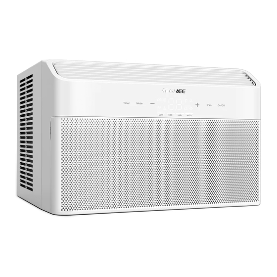
This instruction manual is the universal-purpose version for this product manufactured by Gree Canada. The appearance of the unit that you have purchased may differ from the ones seen in this manual, however it does not change the basic guidelines on how to operate this appliance. -
Page 4: Safety Precautions
1.0. SAFETY INSTRUCTIONS 1. SAFETY PRECAUTIONS The following symbols and labels are used throughout this manual to indicate immediate or potential hazards. It is the owner’s responsibility to read and follow all safety information and instructions accom- panying these symbols. Failure to heed safety information increases the risk of serious injury or death, property damage and/or product damage. - Page 5 1. SAFETY PRECAUTIONS Electrical Safety CAUTION : The power cord of this air conditioner contains a current sensing device designed to reduce the risk of fire. Please refer to the Operation of Current Device section below for more details. If the power cord is damaged, it cannot be repaired. It must be replaced with a power cord from the product manufacturer.
- Page 6 1.0. SAFETY INSTRUCTIONS 1. SAFETY PRECAUTIONS The Refrigerant To perform its air conditioning functions, the unit uses a special type of refrigerant, fluoride R32, a partic- ularly clean refrigerant. It is flammable and odourless. Furthermore, it can cause an explosion under cer- tain conditions.
-
Page 7: Air Conditioner Overview
2. AIR CONDITIONER OVERVIEW COMPONENTS 1. Side exhaust vents 5. Air inlet 9. Airflow direction adjustment knob 2. Air outlet 6. Bottom mounting rail 10. Front panel 3. Control panel 7. Top exhaust vents 11. Power plug 4. Side mounting rail 8. -
Page 8: Air Conditioner Installation
1.0. SAFETY INSTRUCTIONS 3. AIR CONDITIONER INSTALLATION 3.1. PRE-INSTALLATION INFORMATION CAUTION : When handling the unit, take care to avoid cutting yourself on the sharp metal edges and aluminum fins of the front and rear coils. WARNING : ▪ Observe all electrical codes and ordinances. ▪... - Page 9 3. AIR CONDITIONER INSTALLATION Installation Location Recommendations ▪ Make sure there are no object in the vicinity of the unit that could obstruct the indoor air inlet or outlet, or the outdoor exhaust air vents. 343 mm (13.5 in) ▪ Choose a window where condensation water can be easily dispersed to the back of the unit and will not affect others.
-
Page 10: Installation Instructions
1.0. SAFETY INSTRUCTIONS 3. AIR CONDITIONER INSTALLATION 3.2. INSTALLATION INSTRUCTIONS Required Tools Phillips-head screwdriver Pencil Level Flat-head screwdriver Ruler or measuring tape Scissors or x-acto knife Peel the film from the back of the adhesive foam seal C. Top mounting rail Align the strip with the lower edge of the top mount- ing rail, then press it onto the mounting rail to seal completely. - Page 11 3. AIR CONDITIONER INSTALLATION Before fixing the flexible screen panels to the unit, Screen panel frame (right) place a piece of sponge strip along the frame on the right side of the panel marked RIGHT, as shown in the illustration. Repeat the same step on the left side of the panel marked LEFT.
- Page 12 1.0. SAFETY INSTRUCTIONS 3. AIR CONDITIONER INSTALLATION Place the air conditioner on the sill with the lower Window sash mounting rail against the rear edge. Center the unit and Top mounting rail close the window securely behind the top mounting rail. Inclination of The unit should be tilted slightly outwards.
- Page 13 3. AIR CONDITIONER INSTALLATION Insert the foam seal B between the glass and the win- dow sash to prevent air from seeping into the room. If Foam seal B the strip does not fit properly to your window, acquire an appropriate material from a local store to ensure a proper seal.
-
Page 14: Operation Guide
1.0. SAFETY INSTRUCTIONS 4. OPERATION GUIDE 4.1. CONTROL PANEL BUTTONS AND INDICATORS SYMBOL DESCRIPTION On/Off Power button Fan Speed selection button Temperature/time decrease button Temperature/time increase button Mode Mode selection button Timer Timer setting button 2-digit temperature/time display Energy Saver mode indicator Cool mode indicator Sleep mode indicator Filter Check indicator... -
Page 15: Remote Control Button
4. OPERATION GUIDE 4.2. REMOTE CONTROL BUTTONS SYMBOL DESCRIPTION Power button Fan Speed selection button Sleep mode button I Feel mode button Mode selection button Swing button (not available) Timer setting button Light button Temperature/time adjustment button NOTICE : This is a general purpose remote control which is used for a variety of air conditioners. Some functions may not be available on the model you have purchased. - Page 16 1.0. SAFETY INSTRUCTIONS 4. OPERATION GUIDE OPERATION MODE SELECTION Press the Mode ( on the remote) button to select an operation mode from the following options : Auto, Cool, Energy Saver, Dry or Fan. The corresponding indicator will light up on the control panel. Auto : Monitors the room’s ambient temperature and humidity level, and automatically adjusts to provide comfortable room temperature.
- Page 17 4. OPERATION GUIDE TIMER-OFF SETTING ▪ To set a timer to switch off the unit, press the Timer ( on the remote) button while the unit is running. On the remote control, the indicator TIMER OFF will be flashing on the LED screen. ▪...
-
Page 18: Airflow Direction Adjustment
1.0. SAFETY INSTRUCTIONS 2.0. OPERATING PRINCIPLE 4. OPERATION GUIDE 4.4. AIRFLOW DIRECTION ADJUSTMENT Horizontal Airflow Adjustment Adjust the vertical flaps to the left or right to direct the airflow according to your preference using the adjustment knob. Adjustment knob Vertical Airflow Adjustment Adjust the horizontal flaps up or down to direct the airflow according to your preference. -
Page 19: Care And Maintenance
3.0. MAIN COMPONENTS 5. CARE AND MAINTENANCE WARNING : ▪ Turn off the air conditioner and unplug the power cord from the outlet before cleaning to avoid electric shock. ▪ Do NOT wash the air conditioner with water to avoid electric shock. ▪... - Page 20 1.0. SAFETY INSTRUCTIONS 2.0. OPERATING PRINCIPLE 5. CARE AND MAINTENANCE Post-season Storage 1. Set the temperature at 30 °C (86 °F) and let the unit run for half a day. This is to dry the inside of the unit. 2. Turn off the air conditioner and disconnect the power cord. 3.
-
Page 21: Troubleshooting
3.0. MAIN COMPONENTS 6. TROUBLESHOOTING WARNING : If the situations below are observed, please turn off the air conditioner and immediately unplug the power cord from the outlet and contact Customer Service : ▪ Overheating or damaged power cord. ▪ Abnormal sounds during operation. ▪... -
Page 22: Common Issues
1.0. SAFETY INSTRUCTIONS 2.0. OPERATING PRINCIPLE 6. TROUBLESHOOTING 6.3. COMMON ISSUES If your appliance appears defective, please check the possible explanations for your situation in the table below, it may be that a simple solution can help solve the problem. If the problem persists, please call 1 800 686-2175 for assistance. -
Page 23: Malfunction Codes
3.0. MAIN COMPONENTS 6. TROUBLESHOOTING The remote control The distance between the appliance and Get closer to the unit so the remote control signal can does not work. the remote control is too great. reach the main unit's receiver. The remote control is not properly aligned Make sure to be facing the unit when pressing keys with the main unit’s signal receiver. -
Page 24: Warranty
Note : The compressor is covered by a 5-year limited warranty. During the warranty period, if the product fails under normal use, Gree Canada will, at its option, either repair the unit or replace it, free of charge, within a reasonable period of time after the product is returned.
Need help?
Do you have a question about the GJC08BU-A6NRNJ2A and is the answer not in the manual?
Questions and answers