Download Print this page
Gree GJC07AF Series Service Manual

Gree GJC07AF Series Service Manual

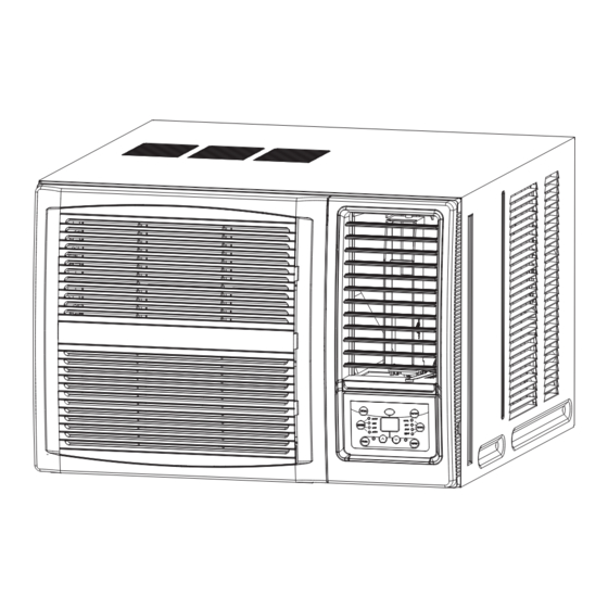
Gree window air conditioner

Advertisement

Quick Links

Change for Life

Service Manual

GREE ELECTRIC APPLIANCES,INC.OF ZHUHAI

Advertisement

loading
Need help?

Need help?

Do you have a question about the GJC07AF Series and is the answer not in the manual?

Questions and answers

Summary of Contents for Gree GJC07AF Series

  • Page 1: Service Manual

    Change for Life Service Manual GREE ELECTRIC APPLIANCES,INC.OF ZHUHAI...
  • Page 3 MODE ON/OFF CLOCK TIMER ON TIMER OFF ENERGY LIGHT SAVER SLEEP...
  • Page 18 Over500...
  • Page 19 indoor heat centrifugal exchanger axial flow blade blade cool wind hot wind compressor outdoor heat exchanger electric heater (Note: electric heater is not available for cooling only unit) capillary flow direction of refrigerant...
  • Page 20: Fan Motor

    BN(BK) POWER MODULE TUBE TEMP. ROOM TEMP. SENSOR SENSOR BU(WH) YEGN(GN) CN31 CN30 POWER ROOM TUBE W4 BU CAP. PRINTED CIRCUIT BOARD COMP (RD) R(M) COMP YEGN YEGN COMP. CAP. SWING MOTOR FAN MOTOR...
  • Page 21 BN(BK) POWER MODULE OUTTUBE TEMP. TUBE TEMP. SENSOR SENSOR BU(WH) CN31 CN30 YEGN(GN) POWER ROOM TEMP. SENSOR CN6 CN5 OUTTUBE TUBE ROOM W1BK PRINTED CIRCUIT BOARD CAP. COMP W2BU W3YE R(M) COMP YEGN COMP. YEGN SWING 4-WAY CAP. MOTOR VALVE FAN MOTOR...
  • Page 24: Ventilation Lever

    Note:If wireless remote controller is lost, open the surface panel and operate manually. POWER BUTTON SIGNAL RECEIVER Operation starts when pressing this button, and stops when pressing this button again. MODE BUTTON SWING BUTTON Select the operation mode, AUTO, HEAT, COOL, FAN, Activate the automatic air swing function.
  • Page 25: Sleep Button

    SLEEP Signal transmitter SLEEP button ● Press this button, Sleep On and Sleep Off can be selected. After powered on,Sleep Off is defaulted. After the unit is turned off, the Sleep function is canceled. After Sleep function set up, the signal of Sleep will display.
  • Page 26: Light Button

    TIMER ON TIMER ON BUTTON ● At unit off, press Timer On button, "HOUR ON" will blink and display,signal will be concealed, in the timer on setting.During 5 seconds blinking,the value can be adjusted by pressing + or - button, every press of this button, 0.5hour will be increased or decreased, but contin- uously press the + or - button, 2 seconds...
  • Page 28 Slightly to press the place with , along the arrowhead direction to push the back cover of wireless remote control. (As show in figure) Take out the old batteries. (As show in figure) Insert two new AAA1.5V dry batteries, and pay attention to the polarity. (As show in figure) Attach the back cover of wireless remote control.
  • Page 32 The Refrigerant To realize the function of the air conditioner unit, a special refrigerant circulates in the system. The used refrigerant is the fluorideR32,which is specially cleaned. The refrigerant is flammable and inodorous. Furthermore, it can leads to explosion under certain conditions. But the flammability of the refrigerant is very low. It can be ignited only by fire. Compared to common refrigerants, R32 is a nonpolluting refrigerant with no harm to the ozonosphere.
  • Page 35 1) Remove the sticker from the front panel. 2) Put the unit into the installation hole. Horizontal line ●When installing, make sure the unit is slanted downward to the back to minimize the nosie 6-10mm ●Make sure the installation place is strong enough to minimize the noise and vibration of operation.
  • Page 39 36 35 34 33...
  • Page 41 36 35 34 33...
  • Page 43 36 35 34 33...
  • Page 45 36 35 34 33...
  • Page 47 36 35 34 33...
  • Page 49 36 35 34 33...
  • Page 51 36 35 34 33...
  • Page 53 36 35 34 33...
  • Page 79 Procedure Steps Remove panel assy Open the air-inlet panel; remove the filter; remove the screws in the middle, at the left side and right side of the panel; beat the clasp of cabinet slightly and then remove the panel. air-inlet panel filter screw Remove cabinet...
  • Page 80 Steps Procedure screw 3.Remove electric box Remove the remote control cover; remove the earthing screws and temperature sensor; pull out the electric box. earthing screw temperature sensor temperature sensor screw electric box...
  • Page 81 Steps Procedure 4.Remove top cover top cover sub-assy Remove the screws fixing top cover and then remove the top cover. 5.Remove cross beam,swing louver and air door lever Take out the cross beam; take out the swing louver; remove the screws fixing air door lever and then remove the air cross beam door lever.
  • Page 82 Steps Procedure 6.Remove evaporator Unsolder each connection pipe (Note: discharge the refrigerant completely before unsoldering). Remove screws fixing evaporator and then remove the evaporator. screw evaporator 7.Remove condenser Unsolder each connection pipe (Note: discharge the refrigerant completely before unsoldering). Remove screws fixing condenser and then remove the condenser.
  • Page 83 Steps Procedure 8.Remove axial flow blade Remove the nuts of axial flow blade; remove the washer and then remove the axial flow blade. axial flow blade 9.Remove centrifugal blade Remove the nuts of centrifugal blade and then remove the centrifugal blade. centrifugal blade...
  • Page 84 Steps Procedure 10.Remove motor Remove the screws of motor support; take out the motor support; remove the screws of motor and then remove the motor. motor screw 11.Remove compressor Unsolder each connection pipe (Note: discharge the refrigerant completely before unsoldering). Remove the 3 foot nuts of compressor and then remove the compressor.
  • Page 85 Procedure Steps 1.Remove panel assy Open t he air-inlet panel; remove the filter; remove the screws in the middle, at the left side and right side of the panel; beat the clasp of cabinet slightly and then remove the panel. air-inlet pane filter screw...
  • Page 86 Steps Procedure screws 3.Remove electric box Remove remote control plate, earthing screw and temp sensor in turn. Then remove electric box. screws earthing screw temp sensor temp sensor electric box...
  • Page 87 Steps Procedure 4.Remove top cover top cover sub-assy Remove the screws fixing top cover and then remove the top cover. 5.Remove cross beam,swing louver ,air door lever Take out the cross beam; take out the swing louver; remove the screws fixing cross beam air door lever and then remove the air swing louver...
  • Page 88 Steps Procedure 6.Remove evaporator Unsolder each connecting pipe (Note discharge refrigerant firstly) and then remove screws fixing evaporator. Then remove evaporator. evaporator screws 7.Remove condenser Unsolder each connecting pipe (Note: discharge refrigerant firstly.) Remove screws fixing condenser and then remove condenser. condenser screws screws...
  • Page 89 Steps Procedure 8.Remove axial flow fan blade Remove nut fixing axial flow fan blade and the washer. Then remove axial flow fan blade. axial flow fan blade 9.Remove centrifugal fan blade Remove nut fixing centrifugal fan blade and then remove centrifugal fan blade.
  • Page 90 Steps Procedure 11.Remove motor Remove screws of motor support and then remove motor support. Remove screws of motor and then remove the motor. screws motor 12.Remove compressor Unsolder each connecting pipe (Note: discharge refrigerant firstly) and then remove 3-hold down nuts compressor.
  • Page 95: Gree Electric Appliances,Inc.of Zhuhai

    GREE ELECTRIC APPLIANCES,INC.OF ZHUHAI Add: West Jinji Rd, Qianshan, Zhuhai, Guangdong, China 519070 Tel: (+86-756) 8522218 Fax: (+86-756) 8669426 Email: gree@gree.com.cn Http://www.gree.com HONG KONG GREE ELECTRIC APPLIANCES SALES LIMITED Add: Unit 2612,26/F.,Miramar Tower 132 Nathan Road,TST,Kowloon,HK Tel: (852) 31658898 Fax: (852) 31651029...