Table of Contents
Advertisement
Quick Links
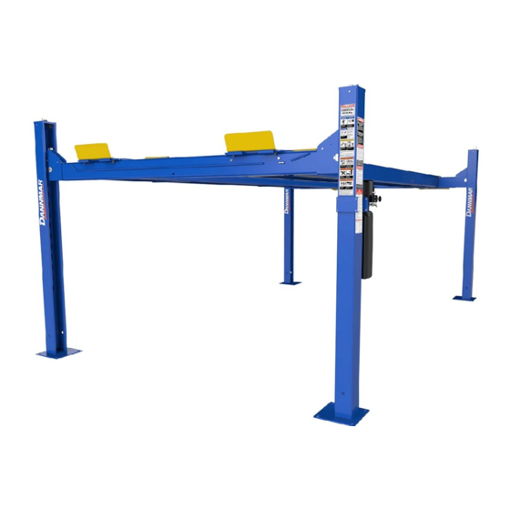
Installation and Operation Manual
Manual P/N 5900246 — Manual Revision B — July 2021
Models:
• D4-12
• D4-12A
⚠
DANGER
Four-Post Lifts
entire
Read the
contents of this manual
product. Failure to follow the instructions and safety precautions in
this manual can result in serious injury or death. Make sure all other
operators also read this manual. Keep the manual near the product
for future reference. By proceeding with installation and
operation, you agree that you fully understand the contents
of this manual and assume full responsibility for product
use .
1645 Lemonwood Dr.
Santa Paula, CA 93060 USA
Telephone: (877) 432-6627
dannmar.com
D4-12A Shown.
before
using this
Advertisement
Table of Contents

Related Manuals for Dannmar D4-12


Summary of Contents for Dannmar D4-12
- Page 1 Santa Paula, CA 93060 USA Telephone: (877) 432-6627 dannmar.com Four-Post Lifts Installation and Operation Manual Manual P/N 5900246 — Manual Revision B — July 2021 Models: • D4-12 • D4-12A D4-12A Shown. ⚠ entire before Read the contents of this manual using this product.
- Page 2 You can always find the latest version of the manual for your product on the Dannmar website. Warranty. The Dannmar warranty is more than a commitment to you: it is also a commitment to the value of your new product. Contact your nearest Dannmar dealer or visit www.dannmar.com/support/warranty/ full warranty details.
-
Page 3: Table Of Contents
Installation Checklist Installation Operation Introduction This manual describes the following Dannmar Four-Post Lifts: D4-12. Four-Post Lift that raises Vehicles up to 12,000 lbs. (5,443 kg). • D4-12A. The Alignment version of the D4-12. • This manual is mandatory reading for all users of the D4-12 Series , including anyone who installs, uses, maintains, repairs, or wants to know more about them. -
Page 4: Safety Considerations
For more information, visit www.p65warnings.ca.gov. General Safety Information The following safety information applies to the D4-12 Series Four-Post Lifts: • The product is a Four-Post Lift. Use it only for its intended purpose. Do not make any modifications to the product. -
Page 5: Components
The main components of your Lift include: D4-12A model shown. Drawing shows the two possible Power Post locations; only one Post has the Brackets for mounting the Power Unit. Not all components are shown. D4-12 Series Four-Post Lifts P/N 5900246 — Rev. B — July 2021... - Page 6 Ladder so that they do not engage as you lower the Runways. Used only to lower the Runways. Usually located next to the Power Post. • Ladders. Part of the Safety Lock System installed at the back of each Post, somewhat resembles a Ladder. D4-12 Series Four-Post Lifts P/N 5900246 — Rev. B — July 2021...
-
Page 7: Specifications
Specifications D4-12 Series Four-Post Lifts P/N 5900246 — Rev. B — July 2021... - Page 8 Lift for a Vehicle with a wheelbase of 100" is 50 percent of the Lift’s rated capacity (or 6,000 lbs. when the rated capacity is 12,000 lbs.). Specifications subject to change without notice D4-12 Series Four-Post Lifts P/N 5900246 — Rev. B — July 2021...
-
Page 9: Installation Checklist
☐ 34. Anchor the Posts. ☐ 35. Perform final leveling. ☐ 36. Install the Accessories. ☐ 37. Lubricate the Lift. ☐ 38. Test the Lift. ☐ 39. Review the final checklist. D4-12 Series Four-Post Lifts P/N 5900246 — Rev. B — July 2021... -
Page 10: Installation
Medium crescent wrench, torque wrench, pipe wrench • Chalk line • Medium-sized flat screwdriver and needle-nose pliers • Tape measure (25 feet or above) • Forklift, Shop Crane, or heavy-duty rolling dolly D4-12 Series Four-Post Lifts P/N 5900246 — Rev. B — July 2021... - Page 11 Install a Thermal Disconnect Switch. Ensures the equipment shuts down in the event of an overload or an overheated motor. Note: None of these components are included with the Lift. D4-12 Series Four-Post Lifts P/N 5900246 — Rev. B — July 2021...
- Page 12 Do not shim a Post more than half an inch using the provided Shims and Anchor Bolts. A maximum shim of 2 inches is possible by ordering optional Shim Plates. Contact Dannmar at 1 (877) 432-6627. • Concrete specifications. Do not install the Lift within 6 inches of cracked or defective concrete.
- Page 13 Checking Clearances Out of a concern for safety, a certain amount of clear space around the Lift is required D4-12 Series Four-Post Lifts P/N 5900246 — Rev. B — July 2021...
- Page 14 This will not impact your use of the Lift in the vast majority of cases, as the length of the wheelbases of the Vehicles you are raising put the Wheels in the Usable Areas. Top view. Drawing not necessarily to scale. Not all components shown. For more information about the Dannmar Rolling Jacks, visit the Rolling Jacks website page.
- Page 15 Installers, you need to have the Lift owner make this decision no later than when Important: moving the Posts into position. Front Driver-side Power Post Location: Rear Passenger-side Power Post Location: D4-12 Series Four-Post Lifts P/N 5900246 — Rev. B — July 2021...
- Page 16 Length value; this includes the Ramps, which are not taken into consideration for creating Chalk Line Guides. Top View. Not drawn to scale. Not all components shown. D4-12 Series Four-Post Lifts P/N 5900246 — Rev. B — July 2021...
- Page 17 Rear Passenger-Side Do not stand up the Posts yet ; some of the following procedures are easier to complete if the Posts are laying on the ground. D4-12 Series Four-Post Lifts P/N 5900246 — Rev. B — July 2021...
- Page 18 Blocks in. Make sure the Slide Blocks are oriented so that they create a Slot when pushed in. Top View. Drawing shows how to correctly install two Slide Blocks onto the Crosstube Gusset. Not all components are shown. D4-12 Series Four-Post Lifts P/N 5900246 — Rev. B — July 2021...
- Page 19 Dropping or knocking over the Posts may cause permanent damage equipment damage or serious personal injury. The Crosstubes and Posts are heavy; do not lift without assistance. 4. Perform Steps 2 and 3 for the other Crosstube. D4-12 Series Four-Post Lifts P/N 5900246 — Rev. B — July 2021...
- Page 20 It is easy to see the top Slot created by the Slide Blocks. It is difficult to see the bottom Slot, but it is required that the Ladder goes through both Slots. 2. Install the remaining Ladders the same way. D4-12 Series Four-Post Lifts P/N 5900246 — Rev. B — July 2021...
- Page 21 Do not securely tighten the Top Nut at the top of the Top Cap at this point; they can be Note: securely tightened after you do the final leveling to the Lift. 6. Install the remaining Top Caps the same way. D4-12 Series Four-Post Lifts P/N 5900246 — Rev. B — July 2021...
- Page 22 Primary Safeties are engaged 4. Once both Crosstubes are in position, , and all four Slack Safeties have been disengaged, you can continue with the installation. D4-12 Series Four-Post Lifts P/N 5900246 — Rev. B — July 2021...
- Page 23 Posts. The difference is the estimated amount of Shim thickness you will need. Do not use Shims and/or Anchor Bolts to shim more than 1/2 an inch. Do not anchor the Posts at this point D4-12 Series Four-Post Lifts P/N 5900246 — Rev. B — July 2021...
- Page 24 2. Make sure the Sheaves have been removed on both ends of the Powerside Runway. Front of Runway: Rear of Runway: Keep the components close, you will be reinstalling them at the same location with the same components later in the installation. D4-12 Series Four-Post Lifts P/N 5900246 — Rev. B — July 2021...
- Page 25 Do not continue with the installation until you have visually confirmed that all four WARNING Safety Locks are engaged. If they are not engaged, the Runways could move or fall, possibly causing personal injury or product damage. D4-12 Series Four-Post Lifts P/N 5900246 — Rev. B — July 2021...
- Page 26 View is from the Rear of the Lift, near the Power Post. Not all components are shown. 4. Let the other end of the Flex Tube hang in place for now. D4-12 Series Four-Post Lifts P/N 5900246 — Rev. B — July 2021...
- Page 27 (such as a Come Along Tool) to extend the Piston and Retaining Plate; be care not to damage the Piston. 4. Reinstall the Shipping Plug to the Return Line Port. D4-12 Series Four-Post Lifts P/N 5900246 — Rev. B — July 2021...
- Page 28 , remove the Nut and Washer from the Threaded End (but keep it nearby, you will need it soon). Check the label to make sure you have the correct Lifting Cable. D4-12 Series Four-Post Lifts P/N 5900246 — Rev. B — July 2021...
- Page 29 Drawing shows the Threaded end of the Lifting Cable in position in the Top Cap. View is from the top of the Post. Not all components are shown. D4-12 Series Four-Post Lifts P/N 5900246 — Rev. B — July 2021...
- Page 30 Routing Lifting Cables B and D is the same process as routing Lifting Cables A and C, just to the other two Posts and using a different set of Sheaves. Refer to the drawings in the previous section. D4-12 Series Four-Post Lifts P/N 5900246 — Rev. B — July 2021...
- Page 31 The Ferrule goes around the Rod and under the Threads. The Nut goes onto the Threads. 6. Tighten the Nut. Remember that the Ferrule can only be used once; do not tighten the Nut until everything is ready. D4-12 Series Four-Post Lifts P/N 5900246 — Rev. B — July 2021...
- Page 32 The Compression Elbow Fittings on the Crosstube Gussets come installed from the factory. Air Lines shown outside Steel Tubes for clarity. Drawing not to scale. Some components not shown. D4-12 Series Four-Post Lifts P/N 5900246 — Rev. B — July 2021...
- Page 33 5. Leave the Power Unit end of the Air Line hanging out of the Flex Tube opening for now. It will be connected to a Tee Fitting and the Pushbutton Air Valve later. D4-12 Series Four-Post Lifts P/N 5900246 — Rev. B — July 2021...
- Page 34 Avoid mixing different types of Hydraulic Fluid. If Hydraulic Fluid needs to be replaced, make sure to flush the Hydraulic System of the old Hydraulic Fluid before you add the replacement Fluid; do not mix the two together. D4-12 Series Four-Post Lifts P/N 5900246 — Rev. B — July 2021...
- Page 35 If you put too much, the excess liquid will be pushed out when the Fitting is tightened; use a rag to wipe the excess. 3. Tighten the Fitting into the connector; do over tighten the Fitting. 4. Allow minimum 24 hours of curing time before pressurizing the system. D4-12 Series Four-Post Lifts P/N 5900246 — Rev. B — July 2021...
- Page 36 Return Line and the Air Lines do completely different things and must be kept separate from each other. Top view. Not drawn to scale. Not all components are shown. D4-12 Series Four-Post Lifts P/N 5900246 — Rev. B — July 2021...
- Page 37 7. Leave the Power Unit end of the Return Line hanging out of the Flex Tube opening for now. It will be connected to the Power Unit later in the installation. D4-12 Series Four-Post Lifts P/N 5900246 — Rev. B — July 2021...
- Page 38 JIC to NPT Hydraulic Fitting. The JIC end goes to the Hydraulic Hose and the NPT end goes to the Hydraulic Cylinder. The following drawing shows the connections to make to the Hydraulic Hose. Drawing not to scale. Not all components are shown. D4-12 Series Four-Post Lifts P/N 5900246 — Rev. B — July 2021...
- Page 39 Once done, the Curved end should be coming out of the Flex Tube opening near the Power Unit. 7. Leave the Curved end of the Hydraulic Hose coming out of the Flex Tube opening for now. D4-12 Series Four-Post Lifts P/N 5900246 — Rev. B — July 2021...
- Page 40 Bolts, M8 Washers, and M8 Nuts. The Power Unit is heavy. We recommend you have one person hold the Power Unit while another person bolts it in place. D4-12 Series Four-Post Lifts P/N 5900246 — Rev. B — July 2021...
- Page 41 2. Fill the Hydraulic Fluid Reservoir on the Power Unit with the appropriate amount of Hydraulic Fluid: 3. When the Reservoir is filled, replace the Reservoir Cap. Do not connect the Power Unit to a power source at this point D4-12 Series Four-Post Lifts P/N 5900246 — Rev. B — July 2021...
- Page 42 5. Holding the Flex Tube by the Plastic Collar, put the Threads through the hole on the Flex Tube from underneath Angle Plate 6. Screw the Plastic Nut back onto the Threads and tighten. D4-12 Series Four-Post Lifts P/N 5900246 — Rev. B — July 2021...
- Page 43 . Double check to make sure you are attaching the Air Line to the Pushbutton Air Valve. For the customer-supplied air pressure, a minimum of 50 to 150 psi / 3 to 25 cfm is required. D4-12 Series Four-Post Lifts P/N 5900246 — Rev. B — July 2021...
- Page 44 2. Connect and securely tighten the ORB end of the Fitting to the Hydraulic Power Out on the Power Unit. 3. Connect and securely tighten the JIC end of the Fitting to the Hydraulic Hose. D4-12 Series Four-Post Lifts P/N 5900246 — Rev. B — July 2021...
- Page 45 The Hydraulic Power Ports are usually labeled P1/P2 on the Power Unit; the Hydraulic Return Ports are commonly labeled T1/T2 or CV1/CV2. The following drawing shows the standard configuration for the Power Unit. Not drawn to scale. Not all components shown. D4-12 Series Four-Post Lifts P/N 5900246 — Rev. B — July 2021...
- Page 46 Wire a Power Cord (with appropriate plug) inside the Electrical Box to the wiring that was connected to the Pigtail. The Power Cord and Plug are supplied with the Lift. Wiring Diagrams for more information. D4-12 Series Four-Post Lifts P/N 5900246 — Rev. B — July 2021...
- Page 47 High electrical current that exceeds the motor’s full load amps (FLA) rating may result in permanent damage to the motor. We strongly recommend that you exceed the rated duty cycle of the Lift’s motor. D4-12 Series Four-Post Lifts P/N 5900246 — Rev. B — July 2021...
- Page 48 Use only the Anchor Bolts that came with your Lift. Only install your Lift on a Concrete floor. Make sure to get the correct amount of Effective Embedment and use the correct amount of Torque. D4-12 Series Four-Post Lifts P/N 5900246 — Rev. B — July 2021...
- Page 49 Concrete or Anchor Bolts do not meet these specifications, it could lead to product damage, Vehicle damage, personal injury, or even death. Dannmar Lifts are supplied with installation instructions and concrete fasteners meeting the criteria as prescribed by the American National Standard “Automotive Lifts – Safety Requirements for Construction, Testing, and Validation”...
- Page 50 Do not shim a Post more than half an inch using the provided Shims. A maximum of 2 inches is possible by ordering optional Shim Plates. Contact Dannmar at 1 (877) 432-6627 with the model and serial number of your Lift.
- Page 51 2. Put a Tire Stop in position over the front of the Runway, then secure in place with a Bolt, Washer, and Nut in each hole. 3. Repeat Steps 1 and 2 for the other Tire Stop. D4-12 Series Four-Post Lifts P/N 5900246 — Rev. B — July 2021...
- Page 52 1. Find the four Crosstube Covers from the Parts Box. 2. Attach the Cover to the top of the Crosstube Gusset; do the same for the remaining Gussets. D4-12 Series Four-Post Lifts P/N 5900246 — Rev. B — July 2021...
- Page 53 For Vehicles with longer wheelbases (i.e. bigger trucks), put the Turn Plate closer to the Rear of the Lift. This orientation prevents Vehicles with longer wheelbases from hanging so far over the Front of the Lift that they interfere with using the Aligner. D4-12 Series Four-Post Lifts P/N 5900246 — Rev. B — July 2021...
- Page 54 Put a small amount of white lithium grease or similar on each lubrication point before you use the Lift and monthly after putting the Lift into service. D4-12 Lubrication Points are all located where you find Cable Sheaves and Gusset Sheaves. Gusset Sheaves (ends of Crosstubes):...
- Page 55 CAUTION Never leave the Lift without making sure that all four Safety Locks have engaged on locking positions at the same height . If one of the four D4-12 Series Four-Post Lifts P/N 5900246 — Rev. B — July 2021...
- Page 56 Make sure a copy of the Installation and Operation Manual is left with the Lift. • If it has not been done already, perform an Operational Test of the Lift with a typical Vehicle. Refer Test the Lift. D4-12 Series Four-Post Lifts P/N 5900246 — Rev. B — July 2021...
-
Page 57: Operation
Check the Lift. Walk all the way around the Lift, checking for any missing, heavily worn, or damaged parts. Do not operate the Lift if you find any issues; instead, take it out of service, then contact your dealer, email support@dannmar.com, or call 1 (877) 432-6627. •... - Page 58 Lowering Handle when they 3. When Runways stop. are fully lowered, Do not press and release Pushbutton hold Pushbutton. and Lowering Handle. Drive Vehicle off Runways. D4-12 Series Four-Post Lifts P/N 5900246 — Rev. B — July 2021...
- Page 59 4. Lower the Runways all the way to the ground, then release the Pushbutton Air Valve and the Lowering Handle. 5. Remove the Tire Chocks, then carefully drive the Vehicle off the Runways. D4-12 Series Four-Post Lifts P/N 5900246 — Rev. B — July 2021...
-
Page 60: Maintenance
⚠ WARNING Do not operate your Lift if you find maintenance issues; instead, take the Lift out of service, then contact your dealer, visit dannmar.com/support, email support@dannmar.com, or call 1 (877) 432-6627. D4-12 Series Four-Post Lifts P/N 5900246 — Rev. B — July 2021... - Page 61 Visually check for any broken wires. One way to check for crown breaks is to run a cloth along the rope to check for possible snags. d. With an awl, probe between wires and strands and raise any wires that appear loose. D4-12 Series Four-Post Lifts P/N 5900246 — Rev. B — July 2021...
-
Page 62: Troubleshooting
Crosstubes using white lithium grease. If the Lift is new, a break-in period may be needed; run the Lift several times each day. If the noises persist, contact Dannmar Support. If you continue to have issues with your Lift, take it out of service, then contact your dealer, go to dannmar.com/support, email... -
Page 63: Wiring Diagrams
Wiring Diagrams 5585280 5585780 5585079 5585176 D4-12 Series Four-Post Lifts P/N 5900246 — Rev. B — July 2021... -
Page 64: Labels
Labels D4-12 Series Four-Post Lifts P/N 5900246 — Rev. B — July 2021... - Page 65 D4-12 Series Four-Post Lifts P/N 5900246 — Rev. B — July 2021...
- Page 66 D4-12 Series Four-Post Lifts P/N 5900246 — Rev. B — July 2021...
-
Page 67: Parts Drawings
*The 127.36 in. / 3,235 mm measurement shown above considers the Bolt Heads that stick out near the bottom of the Posts used for securing the Ladders; this measurement is the Overall Width value to be used when creating Chalk Line Guides. D4-12 Series Four-Post Lifts P/N 5900246 — Rev. B — July 2021... - Page 68 D4-12 Series Four-Post Lifts P/N 5900246 — Rev. B — July 2021...
- Page 69 D4-12 Series Four-Post Lifts P/N 5900246 — Rev. B — July 2021...
- Page 70 D4-12 Series Four-Post Lifts P/N 5900246 — Rev. B — July 2021...
- Page 71 D4-12 Series Four-Post Lifts P/N 5900246 — Rev. B — July 2021...
- Page 72 1645 Lemonwood Drive Santa Paula, CA, 93060 USA © 2021 BendPak Inc. All rights reserved. dannmar.com...
Need help?
Do you have a question about the D4-12 and is the answer not in the manual?
Questions and answers