Table of Contents
Advertisement
Quick Links
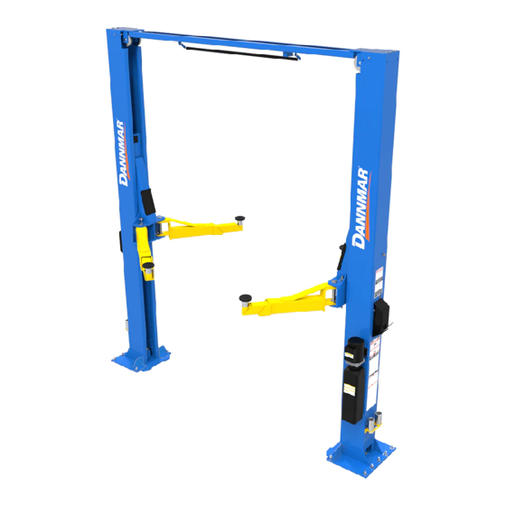
INSTALLATION AND OPERATION MANUAL
12,000/15,000LB / 5,443/6,804 KG CAPACITY
TWO-POST LIFTS
MODELS:
• D2-12C
• D2-15C
Read the entire contents of this manual before using this product.
Failure to follow the instructions and safety precautions in this manual
can result in serious injury or death. Make sure all other operators
also read this manual. Keep the manual near the product for future
reference. By proceeding with setup and operation, you agree that
you fully understand the contents of this manual and assume full
responsibility for product use.
1
1645 Lemonwood Dr.
Santa Paula, CA. 93060, USA
Telephone: (877) 432-6627
www.dannmar.com
P/N 5900252
Rev A - October 2020
Advertisement
Table of Contents

Subscribe to Our Youtube Channel
Related Manuals for Dannmar D2-12C


Summary of Contents for Dannmar D2-12C
- Page 1 INSTALLATION AND OPERATION MANUAL 12,000/15,000LB / 5,443/6,804 KG CAPACITY TWO-POST LIFTS MODELS: • D2-12C • D2-15C P/N 5900252 Rev A - October 2020 Read the entire contents of this manual before using this product. Failure to follow the instructions and safety precautions in this manual can result in serious injury or death.
- Page 2 Our comprehensive product warranty means more than a commitment to you; it’s also a commitment to the value of your new Dannmar lift. For full warranty details and to register your new lift contact your nearest Dannmar dealer or visit the Dannmar website.
-
Page 3: Owner's Responsibility
OWNER’S RESPONSIBILITY IMPORTANT NOTICE To maintain the lift and user safety, the responsibility of the owner is to read and follow these instructions: Do not attempt to install this lift if you have never been trained on basic automotive lift installation procedures. Follow all installation, operation, and maintenance Never attempt to lift components without proper lifting tools such as forklift or cranes. -
Page 4: Table Of Contents
TABLE OF CONTENTS Contents Page No. Warranty / Serial Number Information ............. . 2 Definitions of Hazard Levels . - Page 5 INSTALLER / OPERATOR PROTECTIVE EQUIPMENT t I understand that Dannmar lifts are supplied with concrete fasteners meeting the criteria of the latest ver- sion of the American National Standard “Automotive Lifts - Safety Requirements for Construction, Testing, and Validation”...
-
Page 6: Important Safety Instructions
IMPORTANT SAFETY INSTRUCTIONS Read these safety instructions entirely. Refer to ANSI/ALI ALIS Standard (R2015) Safety Requirements for Installation and Service of Automotive Lifts for more information about safely installing your Lift. • Read understand instructions safety warnings before operating lift. •... -
Page 7: Tools Required
28 days minimum. This lift must be installed on a solid level concrete floor with no more than 3-degrees of slope. Failure to do so could cause personal injury or death. IMPORTANT NOTE: Dannmar lifts supplied with installation instructions and concrete fasteners meeting the criteria as prescribed by the American National Standard "Automotive Lifts - Safety Requirements for... - Page 8 When removing the lift from shipping angles, pay close attention as the posts can slide and can cause injury. Prior to removing the bolts, make sure the posts are held securely by a Forklift or other heavy lifting device COMPONENTS Make sure to take a complete inventory of parts prior to beginning installation.
-
Page 9: Specifications
SPECIFICATIONS D2-12C D2-15C MODEL Lifting Capacity 12,000Lbs. / 5,443 Kg. 15,000Lbs. / 6,804 Kg. Max Capacity/ Front Axle 6,000 lbs. / 2,722 Kg. 7,500 lbs. / 3,408 Kg. Max Capacity/ Rear Axle 6,000 lbs. / 2,722 Kg. 7,500 lbs. / 3,408 Kg. -
Page 10: Clearances
CLEARANCES D2-12C AND D2-15C APPROACH LIFT HEIGHT CLEARANCE NOTE: There must be a 1” MIN distance from top of lift to nearest obstruction. -
Page 11: Step 3 / Column Preparation
STEP 3 (Column Preparation) COMPLETE THE FOLLOWING Cable routed up PRIOR TO STANDING UP COLUMNS. and across Over- head Assembly to Threaded Cable opposite carriage. end from other 1. Slide Lift Head up Column to access the Cable side of lift. Sheave and Equalizer Cable routing. -
Page 12: Equalizer Cable Routing
6. Route both Hoses in their respective Columns PRIOR Fig 3.6 to standing up the Columns. When routing the Hydraulic Hose through the Columns, make sure to route through the Retaining Clips welded inside each Column. Make M10 Hex sure that the Hose is clear of any moving parts. It may be M10 Hex necessary to tie Hose clear of obstructions by using nylon Head Bolt... -
Page 13: Hose Routing
HOSE ROUTING Side of Column... - Page 14 FLOOR PLAN APPROACH Model Capacity D2-12C 155.25” / 3,941 mm 12,000 lbs D2-15C 155.25” / 3,941 mm 15,000 lbs STEP 4 4. Once a location is determined, use chalk line to layout an alignment line for the Post locations. (Site Layout) Keep all dimensions square within 1/8”...
- Page 15 (Installing The POWERSIDE Column) clockwise. DO NOT use an impact wrench for this NOTE: procedure. (See Fig. 5.4) DANNMAR LIFTS ARE SUPPLIED WITH INSTALLATION INSTRUCTIONS AND CONCRETE FASTENERS MEETING THE CRITERIA AS PRESCRIBED BY THE LATEST VERAMERICAN NATIONAL STANDARD "...
-
Page 16: Step 7 / Mounting The Overhead Assembly
STEP 8 NOTE: (Mounting the Hydraulic Power Unit) REMOVE THE CABLE SHEAVES PRIOR TO EQUALIZER CABLE ROUTING. 1. Attach the power unit to the POWER SIDE Column. Install the vibration dampener between the power unit and the power unit mounting plate on the Power Side Column, STEP 7 using four M8 hex head bolts and nuts supplied. -
Page 17: Step 9 / Installing The Safeties And Safety Cable
DO NOT RUN POWER UNIT WITHOUT OIL. DAMAGE TO POWER UNIT PUMP CAN OCCUR. THE POWER UNIT MUST BE KEPT DRY. DAMAGE TO POWER UNIT CAUSED BY WATER OR OTHER LIQUIDS SUCH AS DETERGENTS, ACID ETC., IS NOT COVERED UNDER WARRANTY. OPERATE LIFT ONLY BETWEEN TEMPERATURES OF 41 °- 104°... - Page 18 NOTE: ENSURE THAT BOTH THE POWER SIDE & OFF AKE SURE TO KEEP THE SAFETY CABLE SIDE SAFETIES ENGAGE PROPERLY PRIOR TO CENTERED WHEN TIGHTENING JAM NUTS LIFT OPERATION. ON SAFETY. Fig 9.3 NOTE: Top plate cut away for clarity Safety Cable Insert non-looped...
-
Page 19: Step 10 / Installing Hydraulic Hoses
STEP 10 (Installing Hydraulic Hoses) 1. Install the Hydrualic Tee Fitting into the Power Side Column. The through hole is located approximately 90 inches from the floor on the back wall of the Power Side WHEN THE CABLE ADJUSTING NUTS BOTTOM OUT Column. -
Page 20: Step 12 / Installing Overhead Microswitch
STEP 12 Fig. 11.2 (Installing Overhead Micro Switch) Equalizer Cables MICROSWITCH WIRE MUST BE RUN THROUGH CLIPS IN POST AND OVERHEAD ASSEMBLY. Sheave FAILURE TO DO SO CAN CAUSE DAMAGE Brackets TO LIFT OR TO VEHICLES. Cable Sheaves Fig. 11.3 Threaded Cable End Microswitch... - Page 21 3. Route wire up through Column and across Overhead Assembly through hole in Overhead Assembly into the 2. Install the Elbow Fitting w/ O-ring into the Hydraulic Microswitch box. (See Fig. 12.3) Pressure Port of the Power Unit. Connect the Power Unit Hose to the Elbow Fitting (See Fig.
-
Page 22: Step 14 / Installing The Lift Arms
THE ARM RESTRAINT GEARS MUST BE POSITIONED PROPERLY. CONFIRMATION OF PROPER GEAR ENGAGEMENT MUST BE MADE PRIOR TO THE OPERATION OF THE LIFT. Screw PERIODIC INSPECTION IS REQUIRED. FAILURE TO INSPECT THE ARM RESTRAINT GEARS ON ALL FOUR ARMS PROPERLY CAN RESULT IN DAMAGE TO THE VEHICLE OR INJURY AND/OR DEATH. - Page 23 NOTE: EACH ARM RESTRAINT ASSEMBLY MUST BE INSPECTED BEFORE EACH AND EVERY TIME THE LIFT IS OPERATED. DO NOT OPERATE THE LIFT IF ANY OF THE FOUR ARM RESTRAINT SYSTEMS ARE NOT FUNCTIONING PROPERLY. REPLACE ANY BROKEN COMPONENTS OR COMPONENTS WITH BROKEN TEETH ONLY WITH AUTHORIZED OR APPROVED REPLACEMENT PARTS.
- Page 24 CARRIAGE STOP BOLT INSTALLATION YOU MUST RE-INSTALL TOP CARRIAGE-STOP BOLT (SHOWN BELOW). TIGHTEN CARRIAGE-STOP BOLT TO 2-3 POUND FEET OF TORQUE UPON FINAL INSTALLATION INSPECTION. THESE INSTRUCTIONS MUST BE FOLLOWED TO ENSURE PROPER INSTALLATION AND OPERATION OF YOUR LIFT. FAILURE TO COMPLY WITH THESE INSTRUCTIONS CAN RESULT IN SERIOUS BODILY INJURY AND/OR DEATH AND/OR VOID PRODUCT WARRANTY.
- Page 25 DO NOT PERFORM ANY MAINTENANCE OR INSTALLATION OF ANY COMPONENTS WITHOUT FIRST ENSURING THAT ELECTRICAL POWER HAS BEEN DISCONNECTED AT THE SOURCE OR PANEL AND CANNOT BE RE-ENERGIZED UNTIL ALL MAINTENANCE AND/OR INSTALLATION PROCEDURES ARE COMPLETED. IMPORTANT POWER-UNIT INSTALLATION NOTES n DO NOT run Power Unit with no oil.
-
Page 26: Step 15 / Power Unit Connection
STEP 16 STEP 15 (Final Adjustments / Post-Installation Checklist) (Power Unit Connection) 1. Have a certified electrician run the power supply to motor. Refer to the data plate found on the motor for proper power supply and wire size. DURING THE START-UP PROCEDURE, OBSERVE ALL OPERATING COMPONENTS AND CHECK FOR PROPER INSTALLATION AND ADJUSTMENT. - Page 27 STEP 17 NOTE: (Lubrication) There will be initial stretching of the cables and/or with increased loads. Adjust the cables as outlined above . After installation and start up has been completed, a week after first use, then every three to six months lubricate lift components as shown below.
- Page 28 • ALWAYS keep area around lift free of tools, debris, or if it has broken or damaged parts. Use only qualified grease and oil. lift service personnel and genuine Dannmar parts to make • NEVER overload lift. Capacity of lift is shown on repairs.
- Page 29 LIFT OPERATION SAFETY (CONTINUED) • ALWAYS carefully load Vehicle on the Lift. Position the lift adapters to contact at the Vehicle Manufacturer’s recommended lift points. Raise lift until adapters contact vehicle. Check adapters for secure contact with Vehicle. WHEN LOWERING THE LIFT PAY CAREFUL Raise lift to desired working height.
- Page 30 LIFT OPERATION SAFETY (CONT’D) TYPICAL LIFTING POINTS Fig. 19.2 Fig. 19.3 MANY SPECIALTY OR MODIFIED VEHICLES CANNOT BE RAISED ON A TWO-POST FRAME ENGAGING LIFT. CONTACT VEHICLE MANUFACTURER FOR RAISING OR JACKING DETAILS. NOTE: ALLOW (2) SECONDS BETWEEN MOTOR STARTS. FAILURE TO COMPLY MAY CAUSE MOTOR BURNOUT.
- Page 31 LIFT OPERATION SAFETY (CONTINUED) DO NOT go near or under a raised Vehicle if all four adapters are not in secure contact with vehicle at vehicle manufacturer’s recommended lift points. WHEN LOWERING THE LIFT PAY CAREFUL ATTENTION THAT ALL PERSONNEL AND Repeat entire loading and raising procedures if OBJECTS ARE KEPT CLEAR.
- Page 32 LIFT OPERATION SAFETY (CONT’D) • Always replace ALL FAULTY PARTS before lift is put • Monthly: Check equalizer cable tension. Adjust per lift installation instructions. back into operation. • Monthly: Lubricate locking latch shafts. Push latch • Daily: Make a visual inspection of ALL MOVING handle several times for oil to penetrate pivot points.
- Page 33 TO RAISE LIFT Read operating and Safety manuals before using lift. Always lift a vehicle according to the manufacturers recommended lifting points. Position vehicle between columns. Adjust swing arms so that the vehicle is positioned with the center of gravity midway between pads. Use truck adapters as needed.
- Page 34 WIRE ROPE INSPECTION AND MAINTENANCE Lifting cables should be replaced every three - five years or when visible signs of damage are apparent. DO NOT USE LIFT WITH DEFECTIVE / WORN CABLES. Lifting cables should be maintained in a well-lubricated condition at all times. Wire rope is only fully protected when each wire strand is lubricated both internal and external.
- Page 35 Safe Lift Operation It is your responsibility to operate your lift safely. Lift training should include, but not be limited to, the following: • Proper positioning of the vehicle on the lift arms. (See manufacturers minimize wheel base loading requirements.) •...
- Page 36 • Do not leave the controls while the lift is still in motion. • Do not stand directly in front of the vehicle or in the bay when vehicle is being loaded or driven into position. • Do not go near vehicle or attempt to work on the vehicle when being raised or lowered. •...
-
Page 37: Troubleshooting
Lift makes weird noises. Lubricate hinge points using white lithium grease. If you continue to have issues with your Lift, take the Lift out of service, then contact your dealer or Dannmar Support at Dannmar.com/support or by phone at (877) 432-6627.
Need help?
Do you have a question about the D2-12C and is the answer not in the manual?
Questions and answers