Table of Contents
Advertisement
Dannmar Equipment
646 Flinn Avenue
Moorpark, CA 93021
Tel: 1-877-432-6627
www.dannmar.com
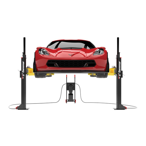
M-6 USER MANUAL
MODEL: M-6
PN# 1375685
PORTABLE MID-RISE LIFT
6,000 POUND CAPACITY
Previoulsy known as
MX6
MJ-GCE
Patent No. US 8.256.577 B2
Patent No. US 9.150.395 B2
Rev B 062018
Rev B 062018
P/N# 17404004
P/N# 17404004
Reference ANSI/ALI ALIOM safety
requirments for installation and service of
automotive lifts before installing lift.
PLEASE READ THE ENTIRE CONTENTS OF THIS MANUAL PRIOR TO INSTALLATION AND OPERATION. BY PROCEEDING WITH LIFT
INSTALLATION AND OPERATION YOU AGREE THAT YOU FULLY UNDERSTAND AND COMPREHEND THE FULL CONTENTS OF THIS
MANUAL. FORWARD THIS MANUAL TO ALL OPERATORS. FAILURE TO OPERATE THIS EQUIPMENT AS DIRECTED MAY CAUSE
INJURY OR DEATH.
Dannmar
EQUIPMENT
©2018 DANNMAR EQUIPMENT. ALL RIGHTS RESERVED.
1
R
Advertisement
Table of Contents

Related Manuals for Dannmar M-6


Summary of Contents for Dannmar M-6
- Page 1 INSTALLATION AND OPERATION YOU AGREE THAT YOU FULLY UNDERSTAND AND COMPREHEND THE FULL CONTENTS OF THIS MANUAL. FORWARD THIS MANUAL TO ALL OPERATORS. FAILURE TO OPERATE THIS EQUIPMENT AS DIRECTED MAY CAUSE INJURY OR DEATH. ©2018 DANNMAR EQUIPMENT. ALL RIGHTS RESERVED.
-
Page 2: Table Of Contents
TABLE OF CONTENTS IMPORTANT NOTICE / DEFINITIONS OF HAZARD LEVELS IMPORTANT SAFETY INSTRUCTIONS 4 - 5 OWNER / EMPLOYER RESPONSIBILITIES 6 - 7 INSTALLER / OPERATOR PROTECTIVE EQUIPMENT PARTS INVENTORY / ASSEMBLY DIAGRAM 8 - 9 PARTS BAG CONTENTS / PARTS BOX CONTENTS INSTALLATION INSTRUCTIONS / SELECTING SITE / FLOOR REQUIREMENTS INSTALLING HYDRAULIC CYLINDERS MOUNTING THE HYDRAULIC POWER UNIT... -
Page 3: Important Notice / Definitions Of Hazard Levels
These instructions must be followed to insure proper installation and operation of your lift. 9. Dannmar Equipment will assume no liability for loss or damage of any kind, expressed or implied resulting from improper installation or use of this product. -
Page 4: Important Safety Instructions
IMPORTANT SAFETY INSTRUCTIONS READ THESE SAFETY INSTRUCTIONS ENTIRELY Do not attempt to install this lift if you have never been trained on basic automotive lift installation procedures. Never attempt to lift components without proper lifting tools such as a forklift or crane. Stay clear of any moving parts that can fall and cause injury. - Page 5 Contact Dannmar Equipment for information pertaining to certified attachments, accessories, or configuration modifying components.
-
Page 6: Owner / Employer Responsibilities
• I understand that Dannmar lifts are designed to be installed in indoor locations only. Failure to follow installation in- structions may lead to serious personal injury or death to operator or bystander or damage to property or lift. -
Page 7: Installer / Operator Protective Equipment
Please read entire manual prior to installation. Do not operate this machine until you read and understand all the dangers, warnings and cautions in this manual. For additional copies or further information, contact: Dannmar Equipment 646 Flinn Ave. Moorpark, CA 93021... -
Page 8: Parts Inventory / Assembly Diagram
LABEL, SAFETY WARNING STICKER LABEL, SAFETY WARNING STICKER 17401006 LABEL, CAPACITY WARNING STICKER 17401007 LABEL, SAFETY LOCK STICKER 17158151 CE ONLY, ARM FOOT GUARD, LEFT HAND 17158152 CE ONLY ARM FOOT GUARD, RIGHT HAND ©2018 DANNMAR EQUIPMENT. ALL RIGHTS RESERVED. - Page 9 ©2018 DANNMAR EQUIPMENT. ALL RIGHTS RESERVED.
-
Page 10: Parts Bag Contents / Parts Box Contents
FRAME CRADLE PAD ASSEMBLY FRAME CRADLE PAD ASSEMBLY 17157007 17157007 MOTORCYCLE ADAPTER KIT MOTORCYCLE ADAPTER KIT 100121 100121 ANCHOR EPOXY KIT ANCHOR EPOXY KIT 17108042 17108042 6" LONG LIFT PAD EXTENSION 6" LONG LIFT PAD EXTENSION ©2018 DANNMAR EQUIPMENT. ALL RIGHTS RESERVED. -
Page 11: Installation Instructions / Selecting Site / Floor Requirements
INSTALLATION INSTRUCTIONS TOOLS REQUIRED • Hex Key / Metric Allen Wrench Set • Rotary Hammer Drill or Similar • Large Crescent Wrench • 7/8" (22mm) Masonry Bit • Hammer • Large Phillips Screwdriver • 4 Foot Level (1.5 M) • Chalk Line •... -
Page 12: Installing Hydraulic Cylinders
Fitting Assembly Fitting Assembly P/N 17206020 P/N 17206020 P/N 17206020 P/N 17206018 P/N 17206018 P/N 17201017 P/N 17201017 Fig. 5 Fig. 5 P/N 17200006 P/N 17200006 Fig. 4 Fig. 4 P/N 17200010 P/N 17157001 ©2018 DANNMAR EQUIPMENT. ALL RIGHTS RESERVED. -
Page 13: Mounting The Hydraulic Power Unit
When facing the flow divider, the bolt heads should be on the left side. The lift will not work properly if the flow divider is installed upside down. ©2018 DANNMAR EQUIPMENT. ALL RIGHTS RESERVED. -
Page 14: Site Layout
Light duty / sport trucks 115" (2921mm) - 120" (3048mm) Typical Full size trucks 120" (3048mm) - 135" (3429mm) Typical Use the edge of the base plate to line up the posts along the chalk line. Chalk line ©2018 DANNMAR EQUIPMENT. ALL RIGHTS RESERVED. -
Page 15: Installation Of Power Drop Anchors
ANSI B212.15 diameter meeting ANSI B212.15 diameter standards. standards. — — — — Spacer Spacer — — — — 5/8” 5/8” 5/8” — — — — (16mm) (16mm) (16mm) — — — — Anchor Anchor ©2018 DANNMAR EQUIPMENT. ALL RIGHTS RESERVED. - Page 16 Before operating your lift, check to make sure both “A” and “B” measurements are equal. The lift arms must be level before operation. If your lift arms are not level, shim the columns as required. LEVEL LEVEL ©2018 DANNMAR EQUIPMENT. ALL RIGHTS RESERVED.
-
Page 17: Connecting Hydraulic Lines
Motor can not run on 50hz without a physical change in the motor. (US - only) • Use a separate breaker for each power unit. • Protect each circuit with a time delay fuse or circuit breaker. (US-only) ©2018 DANNMAR EQUIPMENT. ALL RIGHTS RESERVED. -
Page 18: Installing The Lift Arms
Foot Guard replacement parts. CE Users: Installing the Arm Foot Guards 1. Install the Foot Guards. They are directional (left/right sided) and will only fit properly on one side or the other. P/N 17158151 17158152 ©2018 DANNMAR EQUIPMENT. ALL RIGHTS RESERVED. -
Page 19: Installing The Safety Release Latch
If the motor gets hot or sounds peculiar, stop and check all electrical connections. 3. Raise the lift to it’s maximum height off the floor until the lift head stops. 4. Lower the lift down below the first safety stop. ©2018 DANNMAR EQUIPMENT. ALL RIGHTS RESERVED. -
Page 20: Final Adjustments / Post Installation Check Off
POST INSTALLATION CHECK OFF Columns are properly leveled Check for overhead obstructions Anchor bolts are tightened Lift arms are level Electric power supply confirmed Arm restraints properly adjusted Check for hydraulic leaks All screws, bolts, and pins are secured Check oil level Surrounding area is clear Lubrication of critical components Operation, maintenance and safety manuals on site... -
Page 21: Lift Operation / Maintenance
Check condition of lift pads and adapters. • Check condition of arm restraints. Adjust as necessary. • Inspect all bolts, pins and anchor bolts. • Replace all faulty parts before lift is put back into operation. ©2018 DANNMAR EQUIPMENT. ALL RIGHTS RESERVED. -
Page 22: Lift Removal / Re-Installation
STEP 14 LIFT REMOVAL 1. Depress the lowering valve on the power unit. 2. Ensure that the lift is lowered all the way to the ground and hydraulic pressure is relieved. 3. Disconnect the power unit from the power source and / or ensure that the power to the circuit is shut off to prevent accidental powering on of the lift while disassembling. -
Page 23: Troubleshooting Guide
TROUBLESHOOTING GUIDE BE SAFE: DO NOT OPERATE OR REPAIR EQUIPMENT WITHOUT READING THIS MANUAL AND THE IMPORTANT SAFETY INSTRUCTIONS. KEEP THIS OPERATION MANUAL NEAR THE LIFT AT ALL TIMES. MAKE SURE THAT ALL USERS READ AND UNDERSTAND THIS MANUAL. LIFT WILL NOT RAISE (BUT MOTOR RUNS) POSSIBLE CAUSE 1. - Page 24 MOTOR WILL NOT RUN POSSIBLE CAUSE 1. Panel circuit breaker flipped, (5,2,1,3,4) 2. Motor burned out, (1,2,3,6,4) 3. Voltage to motor incorrect, (2,1) 4. CE USERS ONLY: Internal motor circuit breaker flipped (7) 5. CE USERS ONLY: Fuse protecting contractor has blown (8) REMEDY INSTRUCTIONS 1.
- Page 25 WILL NOT RAISE ONLY UNDER LOADED CONDITION POSSIBLE CAUSE 1. Air in oil, (4,1,2,3) 2. Cylinder / lift head binding, (5) 3. Cylinder leaks internally, (5) 4. Lift overloaded, (6,5) 5. Lowering valve leaks, (7,1,8,5,9) 6. Motor runs backwards, (10,12,9) 7.
- Page 27 ©2018 DANNMAR EQUIPMENT. ALL RIGHTS RESERVED.
-
Page 28: Limited Warranty
S uch r evised t erms s hall b e e ffective t hirty d ays f rom t he d ate o f s uch ... -
Page 29: Maintenance Records
MAINTENANCE RECORDS... - Page 30 SAFETY LATCH INSTALLATION 1. Insert the safety latch release on to the safety weldment pin. 2. Slide the retaining ring on to safety weldment pin. 3. Slide the safety release assembly on to the safety release plate on the post. 4.
-
Page 31: Overall Lift Specifications
OVERALL LIFT SPECIFICATIONS " 110V(US)-220V(CE) / 50-60 Hz. 1Ph. ©2018 DANNMAR EQUIPMENT. ALL RIGHTS RESERVED. - Page 32 ALTHOUGH EVERY EFFORT HAS BEEN TAKEN TO ENSURE COMPLETE AND ACCURATE INSTRUCTIONS HAVE BEEN INCLUDED IN THIS MANUAL, POSSIBLE PRODUCT UPDATES, REVISIONS AND OR CHANGES MAY HAVE OCCURRED SINCE THE PRINTING OF THIS MANUAL. DANNMAR EQUIPMENT RESERVES THE RIGHT TO CHANGE SPECIFICATIONS WITHOUT INCURRING ANY OBLIGATION FOR EQUIPMENT PREVIOUSLY OR SUBSEQUENTLY SOLD.
Need help?
Do you have a question about the M-6 and is the answer not in the manual?
Questions and answers