
Subscribe to Our Youtube Channel
Related Manuals for SIGNALCORE SC5506A


Summary of Contents for SIGNALCORE SC5506A
- Page 1 SC5506A 25 MHz to 6 GHz RF Signal Source USB, SPI and RS-232 Interfaces Operating & Programming Manual © 2013-2020 SignalCore, Inc. support@signalcore.com...
-
Page 2: Table Of Contents
Default Startup Mode ........................... 11 SC5506A Programming Interface ..............12 Device Drivers ............................12 Using the Application Programming Interface (API) ................12 SPI and RS-232 Programming ....................... 12 Setting the SC5506A: Writing to Configuration Registers ........13 SC5506A Operating & Programming Manual Rev 2.1.1... - Page 3 Setting the Reference DAC Value ......................15 Storing the Startup State ........................15 Setting the RF ALC DAC Value ......................15 Querying the SC5506A: Writing to Request Registers ........16 Reading the Device Temperature ......................16 Reading the Device Status ........................17 Reading the User EEPROM ........................
- Page 4 Writing to the Device via RS-232 ......................33 Reading from the Device via RS-232 ....................33 Using the LabVIEW Functions and NI-VISA ................... 34 Calibration & Maintenance ................35 Revision Notes ....................36 SC5506A Operating & Programming Manual Rev 2.1.1...
-
Page 5: Important Information
Please contact SignalCore if errors are suspected. In no event shall SignalCore be liable for any damages arising out of or related to this document or the information contained in it. -
Page 6: Copyright & Trademarks
SignalCore, Incorporated. SignalCore, Incorporated respects the intellectual property rights of others, and we ask those who use our products to do the same. Our products are protected by copyright and other intellectual property laws. -
Page 7: Recycling Information
Laboratory Equipment include EN 61326-1:2013 and EN 55011:2009 for EMC, and EN 61010-1 for product safety. Recycling Information All products sold by SignalCore eventually reach the end of their useful life. SignalCore complies with EU Directive 2012/19/EU regarding Waste Electrical and Electronic Equipment (WEEE). Warnings Regarding Use of SignalCore Products... -
Page 8: Getting Started
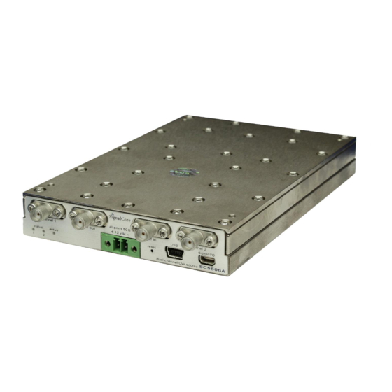
Setting Up and Configuring the SC5506A The SC5506A is a core module-based RF signal source with all I/O connections and indicators located on the front face of the module as shown in Figure 1. Each location is discussed in further detail below. -
Page 9: Power Connection
RF module, just above the screw terminal block. Signal Connections All signal connections (ports) on the SC5506A are SMA-type. Exercise caution when fastening cables to the signal connections. Over-tightening any connection can cause permanent damage to the device. The condition of your system‘s signal connections can significantly affect measurement accuracy and repeatability. -
Page 10: Communication Connections
Depressing this momentary-action push button switch will reset the device to its default state. The SC5506A has the ability to store the current configuration at any point as the default setting. If the factory setting has been overwritten with a saved user configuration, resetting the device will reinitialize the SC5506A Operating &... -
Page 11: Indicator Leds
Refer to the table in the “Default Startup Mode” section of this manual for default settings. Indicator LEDs The SC5506A provides visual indication of important modes. There are three LED indicators on the unit. Their behavior under different operating conditions is shown in Table 3. -
Page 12: Sc5506A Theory Of Operation
P E R A T I O N Output Amplitude Control As shown in Figure 2, the SC5506A source architecture at a high level consists of an output amplitude control section and a frequency synthesis section. The amplitude of the signal is controlled through the use of digital step attenuators (DSAs) and a voltage controlled attenuator (VCA). -
Page 13: Frequency Synthesizer
Frequency Synthesizer The synthesizer section of the SC5506A comprises a multiple phase-locked loop architecture whose base frequency reference is a 10 MHz TCXO. The user may choose to phase-lock this base reference to an external source if required. The 100 MHz VCXO is phase-locked to the TCXO for frequency stability. While the TCXO determines the very close-in phase noise, the VCXO phase noise determines the system phase noise in the frequency offset range of approximately 1 kHz to 30 kHz. -
Page 14: Reference Clock Control
Reference Clock Control As mentioned above, the primary clock reference for the SC5506A is an onboard 10 MHz TCXO. Should the user require better frequency stability and/or accuracy, this TCXO can be programmed to phase-lock to an external source such as an OCXO or rubidium clock. The device can also be programmed to export its internal 10 MHz clock. -
Page 15: Default Startup Mode
2.0 GHz 2.4 GHz Power 0.00 dBm 0.00 dBm RF Output Enabled Enabled ALC Mode Closed Loop Closed Loop Standby Disabled Disabled Auto Level Enabled Enabled Ref Out Disabled Ext Ref Lock Disabled SC5506A Operating & Programming Manual Rev 2.1.1... -
Page 16: Sc5506A Programming Interface
To install the necessary drivers, right click on the sc5506a.inf file in the Win\ directory and choose install. When the device is connected to a USB port, the host computer should identify the device and load the appropriate driver. -
Page 17: Setting The Sc5506A: Writing To Configuration Registers
DAC word [13:8] STORE_STARTUP_STATE 0x23 [7:0] Open Open Open Open Open Open Open Open [7:0] ALC DAC Word [7:0] SET_ALC_DAC_VALUE 0x24 [15:8] ALC DAC Word [13:8] [23:16] Open Open Open Open Open Open Open Channel SC5506A Operating & Programming Manual Rev 2.1.1... -
Page 18: Initializing The Device
RF_ALC_MODE (0x14) – For each channel independently, writing 0x00 to this register puts the ALC in a closed loop operation. Writing 0x01 will run the ALC in an open loop. See the “Output Amplitude Control” section to understand the differences between the modes. SC5506A Operating & Programming Manual Rev 2.1.1... -
Page 19: Setting The Device Standby Mode
Setting the RF ALC DAC Value SET_ALC_DAC_VALUE (0x24) - Writing a 14 bit control word to the ALC DAC register adjusts output amplitude. This is useful when the user wants to make minute adjustments to the power level. SC5506A Operating & Programming Manual Rev 2.1.1... -
Page 20: Querying The Sc5506A: Writing To Request Registers
Negative Temperature (bit 13 is 1) = (ADC code – 8192) / 32 It is not recommended to read the temperature too frequently, especially once the SC5506A has stabilized in temperature. The temperature sensor is a serial device located inside the RF module. Therefore, like any other serial device, reading the temperature sensor requires sending serial clock and data commands from the processor. -
Page 21: Reading The Device Status
RF signal as the serial clock could potentially modulate the internal oscillators. Furthermore, once the SC5506A stabilizes in temperature, repeated readings will likely differ by as little as 0.25 C over extended periods of time. Given that the gain-to-temperature coefficient is on the order of less than -0.01 C, gain changes between readings will be negligible. -
Page 22: Reading The Calibration Eeprom
The frequency value comes back in Hz, occupying 5 returned bytes. The power level come back in 100 dBm masked by 0x7FFF of the first 2 of the 5 bytes. The mask 0x8000 is the sign bit. SC5506A Operating & Programming Manual Rev 2.1.1... -
Page 23: Calibration Eeprom Map
909B Ch1 ALC closed ref DAC value 9195 Ch1 ALC closed coefficients (2 order) 9771 Ch1 ALC opened ref RF power 9965 Ch1 ALC opened ref DAC value 9A5F Ch1 ALC opened coefficient SC5506A Operating & Programming Manual Rev 2.1.1... -
Page 24: Software Api Library Functions
C header file, sc5506a.h. These constants and types are useful not only as an include for developing applications using the SC5506A API, but also for writing device drivers independent of those provided by SignalCore. -
Page 25: Constants Definitions
// read a byte from the calibration EEPROM #define STORE_STARTUP_STATE 0x23 // store the new default state #define SET_ALC_DAC_VALUE 0x24 // set the RF ALC DAC value #define GET_ALC_DAC_VALUE 0x39 // read back the RF ALC DAC value SC5506A Operating & Programming Manual Rev 2.1.1... -
Page 26: Type Definitions
Before reading this API section, please note that there are API changes in revision 2.0 or later. The changes consist of the following: • The API library is renamed from sc5506a.dll to sc5506a_usb.dll for the USB interface to prevent confusion between libraries for USB and RS232. •... - Page 27 The functions listed below are found in the sc5506a.dll or sc5506a_usb.dll dynamic linked library for the Windows operating system. These functions are also provided in the LabView library, sc5506a.llb. The LabView functions contain context help (Cntrl-H) to help with the input and output parameters.
- Page 28 (numOfDevices == 0) printf("No signal core devices found or cannot not obtain serial numbers\n"); for(i = 0; i<MAXDEVICES;i++) free(deviceList[i]); free(deviceList); return printf("\n There are %d SignalCore %s USB devices found. \n \n", numOfDevices, SCI_PRODUCT_NAME); i = 0; while ( i < numOfDevices) printf("...
- Page 29 (Set the mode of initialization) Description: sc5506A_InitDevice initializes (resets) the device. Mode = 0 resets the device to the default power up state. Mode = 1 resets the device but leaves it in its current state. SC5506A Operating & Programming Manual Rev 2.1.1...
- Page 30 (channel name for desired ALC mode change) bool mode (closed or open loop operation of the ALC circuit) Description: sc5506a_SetAlcMode sets the ALC loop to closed or open loop operation for a channel. SC5506A Operating & Programming Manual Rev 2.1.1...
- Page 31 Function: sc5506a_StoreCurrentState Definition: int sc5506a_StoreCurrentState(deviceHandle devHandle) Input: deviceHandle *devHandle (handle to the opened device) Description: sc5506a_StoreCurrentState stores the current state of the devices as the default power- up state. SC5506A Operating & Programming Manual Rev 2.1.1...
- Page 32 *devHandle (handle to the opened device) unsigned char channel (channel name of target ALC DAC) Output: unsigned char *dacValue (the read back byte data) Description: sc5506a_GetAlcDac reads back the current ALC DAC value. SC5506A Operating & Programming Manual Rev 2.1.1...
- Page 33 *deviceParams) Input: deviceHandle *devHandle (handle to the opened device) Output: deviceParams _t * deviceParams (device parameters) Description: sc5506a_GetDeviceParams retrieves device parameters such as frequency and power setting for each channel. SC5506A Operating & Programming Manual Rev 2.1.1...
-
Page 34: Programming The Serial Peripheral Interface (Spi)
SPI signals do not have sufficient integrity due to cabling problems then the rate should be lowered. SignalCore recommends that the clock rate not exceed 1.0 MHz to ensure proper serial operation. As mentioned above, the SPI architecture limits the byte rate due to the fact that after every byte transfer the input and output SPI buffers need to be cleared and loaded respectively by the device SPI engine. -
Page 35: Additional Spi Registers
“Reading the SPI Bus" section below for more information on retrieving data from the device. Figure 5 shows the contents of a single 3 byte SPI command written to the device. Table 5 provides information SC5506A Operating & Programming Manual Rev 2.1.1... -
Page 36: Reading The Spi Bus
Byte 3 Byte2 Byte 1 Byte 0 GET_TEMPERATURE 0x17 valid valid GET_DEVICE_STATUS 0x18 valid valid valid USER_EEPROM_READ 0x1A valid CAL_EEPROM_READ 0x21 valid GET_ALC_DAC_VALUE 0x39 valid valid GET_DEVICE_PARAM 0x25 valid valid valid valid valid SC5506A Operating & Programming Manual Rev 2.1.1... -
Page 37: Programming The Rs-232 Interface
N T E R F A C E The RS-232 version of the SC5506A has a standard interface buffered by an RS-232 transceiver so that it may interface directly with many host devices, such as a desktop computer. The interface connector for RS-232 communication is labeled “Digital I/O”... -
Page 38: Using The Labview Functions And Ni-Visa
The buffers are byte arrays. Most significant data is sent and received first. The number of bytes to be read back from the queried register needs to be specified. SC5506A Operating & Programming Manual Rev 2.1.1... -
Page 39: Calibration & Maintenance
However, SignalCore maintains a calibration data archive of all units shipped. Archiving this data is important should a customer need to reload calibration data into their device for any reason. SignalCore also uses the archived data for comparative analysis when units are returned for calibration. -
Page 40: Revision Notes
Added revision 2 API information to take advantage of firmware revision 4 and later Rev 2.1.0 Added note for pin 8 in Table 2 as reset_b Rev 2.1.1 Corrected SPI information to include device with firmware rev 4 or later SC5506A Operating & Programming Manual Rev 2.1.1...
Need help?
Do you have a question about the SC5506A and is the answer not in the manual?
Questions and answers