Advertisement
Coverage from Side View
A1
170
Coverage from Plan View
A2
8.00m
8.00m
360 Arc
o
Coverage for multiple windows
A3
Window
No 1
8.00m
8.00m
OPTIONAL BACK TAMPER
B5
Please ensure the spring is attached
correctly as illustrated.
The spring is included in the
B1
screw pack.
B5
OPTIONAL BACK TAMPER SWITCH
B3
CABLE ENTRY POINTS
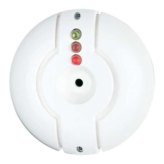
DETECTOR LAYOUT
1. LED's - Green, Orange, Red
B2
Mounting Holes located from
B2
7. Test mode
the inside (All shown in grey).
Min
Max
6. Microphone
5. Sensitivity adjustment
INSTALLAZIONE
I
.
1
Rimuovere il coperchio della custodia svitando la vite di fissaggio contraddistinta con
quindi rimuovere il PCB.
.
2
Montaggio sensore: Scegliere i fori di montaggio contraddistinti con
MONTAGGIO A SOFFITO
: Per una prestazione ottimale, montare il rilevatore di rottura vetro ad
una distanza tra 1 e 3 metri dal vetro - raggio massimo 8 metri.
MONTAGGIO A PARETE
: Per una prestazione ottimale, montare il rilevatore di rottura vetro alla
massima alteza possibile.
NOTA
:Per ottenere i migliori risultati nella protezione di finestre multiple, montare l'unità a soffitto.
.
3
Marcare le posizioni di fissaggio sulla parete/soffito. Evitare installazione a meno di um metro dal
eventuali dotti pneumatici, sirene o campane.
4
Praticare i fori di fissaggio con un trapano.
5
Fissare la custodia alla parete/soffitto.
6
Posizionare la scheda elattronica.
7
Reinserire il coperchio sulla custodia e fissare come illustrato in
DIAGRAMMI
.
A1
Vista laterale. Angolo di copertura - 360, angolo di appertura 170.
.
A2
Vista dall'alto. Copertura massima - 16m in diametro.
Copertura massima per finestre multiple.
A3
Infisso vite di fissaggio
B1
B2
Fori di montaggio parete/soffitto.
B3
Fori d'ingresso cavo
1. LED verde, arancione, rosso; 2. ponticello NORMAL/LATCH, 3. morsettiera,
B4
3. protezzione al manumissione coperchio, 4. potenziometro per aggiustamento
della sensibilità sensore, 5. microfono, 6. ponticello per abilitare la modalità test.
B5
Assicurarsi che il tamper antistrappo sia appropriamente fissato.
.
C1
Dimensioni e peso
D1
= Attivazione bassa frequenza
Indicatori LED:
VERDE
ARANCIONE = Attivazione alta frequenza
ROSSO
= Attivazione allarme
D2
Collegamenti:
1 - Alimenazione ausiliaria,
2 - Manomissione, 3 - Contatti relè N/C
D3
Latch:
Abilitatando il "LATCH" con il ponticello, dopo un'allarme il sensore sarà in allarme fino
a che venisse disalimentato o posizionando il ponticello in posizione "NORMAL".
=
1
2
D4
Modalità test sensore
D4
.
Test sensibilità sensore
Per regolare la sensibilità del sensore utilizzare il Bgreak Glas Tester.
1
D4
Posizionare il ponticello su "TEST" c
ome indicato su
. Entrando in questa modalità
i LED verde e arancione innizieranno lampeggiare
alternativamente per qualche secondo.
.
Per controllare e regolare la sensibilità del Breakglass 2000, posizionare il tester accanto alla finestra
da proteggere. Posizionare pulsante di comando su NORMAL. Premere il pulsante TRIGGER, il tester
imulerà una combinazione di alte frequenze immitando rottura vetro. Osservare i LED verde e
arrancione e utilizzare ilpotenziometro per scegliere la sensibilità appropriata come indicato in seguito:
Attivazione LED verde
= sensore troppo sensibile - abbassare la sensibilità
Attivazione LED arancione
= sensore non sufficentamente sensibile - aumentare la sensibilità
-
Attivazione i LED verde e arancione
= sensibilità corretta
Ottenendo l'ultimo risultato spostare il ponticello di test su "NORMAL" come idicato su
NOTA
: Il sensore tornerà automaticamente alla modalità normale dopo 5 min se il ponticello
non venisse rimosso.
NOTA
: Se dovese verificarsi risultato non soddisfacente regolando la sensibilità del sensore,
.
avvicinare il sensore alla finestra.
,
Prova funzionamento sensore
Assicurarsi di aver rimontato il copechio del sensore.
.
Per controllare il funzionamento del sensore utilizzare il Bgreak Glas Tester.
Posizionare il pulsante di comando su FLEX. Posizionare il BG Tester sulla finestra e premere il
pulsante TRIGGER. Colpire la finestra con un martello di gomma creando la bassa freqenza. Il t
.
ester risponderà emettendo una combinazione di alte frequenze immitando rottura vetro.
La attivazione del LED rosso (allarme) confermerà l'esito del test funzionamento positivo.
Garanzia
IL PRESENTE PRODOTTO VIENE VENDUTO IN CONFORMITÀ ALLE NOSTRE CONDIZION DI GARANZIA STANDARD ED È
GARANTITO DA DIFETTI DI PRODUZIONE PER UN PERIODO DI 2 ANNI.
NELL'INTERESSE DEL CONTINUO MIGLIORAMENTO DELLA QUALITÀ, DEL SERVIZIO ALLA CLIENTELA E DEL DESIGN,
PYRONIX LTD SI RISERVA IL DIRITTO DI MODIFICARE LE SPECIFICHE SENZA PREAVVISO.
30mm
C1
Kg
100g
SPECIFICATIONS (QUICK REFERENCE)
Model:
Breakglass 2000
Colour:
White
Casing:
3mm ABS
Detection method:
Micro processing algorithm sensor
maximized to alarm in all break glass
situations,
Sensor:
Omni -Directional electret microphone
Detection Range:
8m (26ft) Radius
Glass Types:
Float, Plate, Tempered, Wired, Laminated
Leaded, Double glazing
Window
Glass Thickness:
2.4mm to 6.4mm
No 2
Glass Size:
0.3 X 0.3m (1 X 1ft) to 3 X 3 (10 X 10ft)
Operating Voltage:
9-16v DC
Quiescent Current:
30mA 12V
Alarm Output:
Normally Closed Contacts
Mounting Height:
Ceiling Height (8m max)
Test period time out:
Approx 5 mins
Storage Temp:
-40 C to 80 C
Operating Temp:
-30 C to 50 C
Emissions:
EN55022-1
Class B
Immunity:
EN50130-4
D1
LED Indicators
GREEN
ORANGE
RED
D2
Connections
- 12V +
B4
1
. Auxiliary Power
2. Normal
or Latch
D3
D4
Header shown on PCB
Test Mode
3. Terminal Block
Normal
Latch
4. Tamper Switch
1
SP
B1
sul diagramma,
1.
Retirar la tapa de la caja desenroscando los tornillos fijados , indicados por
B2
sul diagramma.
el gráfico, y sacar la placa de circuito impreso.
2.
Seleccionar los agujeros de montaje, indicados por
Montaje en el techo:
metros de distancia del vidrio (radio máximo de 8 metros).
.
Montaje en la pared:
posible.
NOTA
: Para proteger las ventanas, montar la unidad en el techo para conseguir
mejores resultados.
3.
Marcar en la pared / el techo para fijar la ubicación.(No montar la unidad a menos
de un metro de los conductos de aire, de las sirenas o de las campanas)
B1
4.
Taladrar los agujeros de fijación
5.
Fijar la caja en la pared/ el techo.
6.
Volver a colocar la placa de circuito impreso.
7.
Volver a poner la tapa en la caja y acabar de fijar siguiendo las ilustraciones en .
ESQUEMAS
A1
Vista lateral de la cobertura 360º de cobertura y apertura de 180º.
Vista general de la cobertura máxima de un diámetro de 16 metros.
A2
A3
Cobertura para varias ventanas.
B1
Ajuste de los tornillos de fijación.
B2
Agujeros para el montaje en la pared/ el techo.
B3
2 separadores en la entrada del cable.
Composición del detector.
B4
Opcional contra el sabotaje posterior. Asegurarse que el muelle esté
B5
correctamente sujeto antes del montaje del detector. (Incluido en la bolsa de
tornillos).
Dimensiones y peso.
C1
D1
Indicadores LED:
.
=
Modalità normale
D2
Conexiones: , Alimentación auxiliar, , Tamper (sabotaje), , Contactos de relé
N/C
D3
Alarma
En estado de alarma, después de la activación de una alarma, la
unidad seguirá
en este estado hasta su desconexión o si se sitúa el puente en posición normal.
1
D4
=
NOTA
: Los ajustes de la sensibilidad deben realizarse con la tapa frontal retirada.
Ajuste de la sensibilidad del detector
Para probar y ajustar la sensibilidad del Break Glass 2000, usar el Tester Break Glass.
Para situar la unidad en modo de test, volver a posicionar el puente en la placa
principal del circuito impreso en las dos clavijas como se indica en
indicadores LED verde y naranja parpadearán alternativamente para indicar que se ha
introducido el modo de test.
Para probar y ajustar la sensibilidad del Break Glass 2000, situar el Tester del Break Glass cerca
de
la ventana más lejana que se quiera proteger. Situar la tecla de funcionamiento del Tester en
NORMAL y apretar la tecla disparadora (TRIGGER) del Tester. El Tester
del Break Glass emulará un sonido de una rotura múltiple del vidrio.
.
Observar los indicadores del detector Break Glass 2000 y ajustar la sensibilidad usando la
sensibilidad
del potenciómetro siguiendo, a continuación, las instrucciones:
LED verde activado
LED naranja activado
LED verde y naranja activados
Una vez encontrada la sensibilidad apropiada, sacar el puente del modo
de test
NOTA
: Si no se saca el puente del modo de test, el detector se situará automáticamente en
la posición Normal al cabo de 5 minutos.
NOTA
: El objetivo de este test anterior es el asegurar una sensibilidad suficiente, protegiendo de
las falsas alarmas. Si el ajuste de la sensibilidad corresponde al
máximo y si no se puede obtener la sensibilidad correcta, entonces ubique la unidad más
Cerca de la ventana.
INSTALLATION
90mm
1
. Remove case lid by unscrewing fixing screw shown in
remove the PCB.
2
. Choose mounting holes labeled
Ceiling Mounting
: For optimum performance mount the detector between 1 and 3
meters away from the glass (8 meter maximum radius).
Wall Mounting
:
For optimum performance mount the detector
NOTE
: To protect multiple windows mount the unit on the ceiling for best results.
3
. Mark wall / ceiling for fixing positions.
(Do not mount the unit within 1 meter of any air ducts,sirens or bells)
4 Drill fixing holes.
5 Fix case to wall/ ceiling.
6 Replace PCB.
7 Refit lid to case and fasten as illustrated in
DIAGRAMS
Coverage Pattern side view - coverage 360, aperture 170.
A1
Coverage Pattern plan view - max coverage 16m in diameter.
A2
Coverage for multiple windows.
A3
Fixing Screw Fitting.
B1
Wall / Ceiling mounting holes.
B2
Cable entry knockouts.
B3
Detector Layout.
B4
Optional back tamper, ensure the spring is attached correctly before mounting
B5
the detector. (Included in screw pack)
Dimensions and weight.
C1
LED Indicators:
GREEN
D1
ORANGE = Shatter Activation
RED
D2
Connections: , Auxiliary Power, ,Tamper, , N/C relay contacts
1
D3
Latch
- In latch mode after an alarm activation the unit will stay alarmed until
powered down, or the header is moved to normal.
1
2
D4
= Test Mode
D4
NOTE
: The Sensitivity adjustments must be carried out with the front cover removed
Adjusting the sensitivity of the detector
To test and adjust the sensitivity of the Break Glass 2000, use the Break Glass Tester.
To place the unit in test mode, reposition the header on the main PCB on to both pins
as indicated in
Green & Orange LED's will flash alternately to show test mode
D4
1
has been entered.
To test and adjust the sensitivity of the Break Glass 2000, hold the Break Glass Tester
next to the furthest window to be protected. Position the operation button of the tester
to NORMAL and press the TRIGGER tester button. The Break Glass Tester will
emulate a multiple glass break sound.
Observe the LEDs on the Break Glass 2000 detector and adjust the sensitivity using
the sensitivity potentiometer following the following indications:
Green LED activated
= sensitivity too high - lower the sensitivity
Orange LED activated
= sensitivity too low - raise the sensitivity
Green & Orange LED's activated
= Flex activation.
= Shatter activation.
Once the appropriate sensitivity has been achieved remove the header from
= Alarm activation.
Test mode and place in to Normal mode.
NOTE
: If the header is not removed from Test mode the detector will automatically
revert to Normal mode after 5 minutes.
NOTE
: The aim of the above test is to ensure sufficient sensitivity, guarding against
false alarms. If the sensitivity adjustment is set to maximum and the correct
sensitivity cannot be obtained, move the unit closer to the window.
Functional Test
Ensure the front cover is back in place
T
T
N
/
C
To test the functionally of the Break Glass 2000, use the Break Glass Tester.
Position the tester next to the window to be protected
2.
3
Tamper
. N/C relay contacts
Move the operation button of the Tester to FLEX. Press the TRIGGER button of the
tester and hit the centre of the window with a blunt object (rubber hammer) to produce
the flex signal. The Break Glass Tester will respond with a glass breaking sound.
If the Red LED activates, then the test was successful.
Normal
Warranty
THIS PRODUCT IS SOLD SUBJECT TO OUR STANDARD WARRANTY CONDITIONS AND IS WARRANTED
AGAINST DEFECTS IN WORKMANSHIP FOR A PERIOD OF 2 YEARS. IN THE INTEREST OF CONTINUING
2
IMPROVEMENT OF QUALITY, CUSTOMER CARE AND DESIGN, PYRONIX LTD RESERVE THE RIGHT TO
AMEND SPECIFICATIONS WITHOUT GIVING PRIOR NOTICE.
INSTALACIÓN
, en el dibujo.
B2
Para un resultado óptimo montar el detector entre 1 y 3
.
Para un resultado óptimo, montar el detector lo más alto
VERDE
= Activación en caso de flexión
NARANJA = Activación en caso de rotura
ROJO
= Activación de la alarma.
1
2
3
2
D4
a modo de test
=
Normal
1
D4
. Los
= sensibilidad demasiado alta bajar la sensibilidad
= sensibilidad demasiado baja aumentar la sensibilidad
= la sensibilidad es la correcta.
y situarlo en el modo Normal
B1
on diagram and then
B2
on diagram.
as high as possible.
B1
= Flex Activation
= Alarm activation
2
3
= Normal
=
the sensitivity is OK.
D4
1
2
D4
PL
INSTALACJA
1
Zdejmij pokrywę po odkręceniu wkrętów, jak na rys
B1
, en
z elementami elektronicznymi.
2
. Wybierz odpowiednie otwory
B2
Montaż sufitowy
: Czujka optymalnie pracuje w odległości 1 do 3 metrów od okna (maksymalny
zasięg to 8 m).
Montaż ścienny
: Czujka powinna być instalowana jak najwyżej - zapewnia to optymalną pracę
urządzenia.
UWAGA
: W przypadku dozorowania wielu okien zaleca się montaż sufitowy.
3
. Zaznacz miejsca na ścianie/suficie.
(Nie instaluj czujki bliżej niż 1 m od urządzeń wentylacyjnych, dzwonków, sygnalizatorów)
4 Wywierć otwory montażowe.
5 Zamontuj obudowę na ścianie/suficie.
6 Załóż płytkę.
7 Załóż i przykręć pokrywę, jak na rys
B1
RYSUNKI
Obszar detekcji, widok z boku - zasięg 360 stopni, kąt stożkowy 170 stopni.
A1
Obszar detekcji widok z góry - średnica zasięgu 16 m.
A2
Zasięg przy ochronie wielu okien.
A3
Lokalizacja śrub łączących obudowę.
B1
Otwory do montażu ściennego / sufitowego.
B2
Przepusty kablowe.
B3
Wymiary czujki.
B4
Opcjonalnie wyłącznik sabotażowy sygnalizujący zdjęcie czujki, upewnij się przed skręceniem
B5
czujki, czy sprężyna jest dobrze ułożona.
Wymiary i masa.
C1
Wskaźniki LED:
ZIELONY
D1
POMARAŃCZOWY = Wysoka częstotliwość
CZERWONY
Połączenia: , Zasilanie, , Sabotaż, , przekaźnik alarmowy N/C
1
2
D2
Zatrzask
- Takie ustawienie powoduje, że przekaźnik czujki pozostaje otwarty od alarmu do
momentu odłączenia zasilania od czujki lub do przesunięcia zwory do pozycji normalnie.
D3
1
2
D4
D4
= Test
= Normalnie
Uwaga:
Zmiana ustawień czułości musi być przeprowadzana przy zdjętej obudowie.
Regulacja czułości czujki
Włączenie trybu testowania czujki następuję po założeniu zwory na bolce na płytce drukowanej jak
na rys
. Diody migają naprzemiennie pokazując, że czujka jest w trybie testowania.
1
D4
Wyłączenie trybu testowania czujki następuję po zdjęciu zwory z bolców na płytce drukowanej.
Diody migają naprzemiennie. W trybie testowania możliwe jest sprawdzenie czułości czujki
przy pomocy testera.
W celu sprawdzenia i korekcji ustawienia czułości, należy umieścić tester w pobliżu najbardziej
oddalonego chronionego okna. Nacisnąć przycisk TRIGGER, co spowoduje wyemitowanie przez
tester dźwięku tłuczonej szyby. Diody czujki wskażą:
Zielony LED
: zbyt czuła - zmniejsz czułość.
Pomarańczowy LED
: za mało czuła - zwiększ czułość.
Zielony i pomarańczowy LED:
czułość jest odpowiednia, należy powtórzyć test
dla potwierdzenia wyniku. Zdjęcie zwory
że czujka przechodzi do normalnego trybu pracy. Czujka automatycznie przechodzi do trybu
pracy normalnej po 5 minutach od założenia zwory niezależnie od tego czy zwora została
zdjęta czy nie.
Powyższa procedura testowania czujki umożliwia ustawienie czułości na takim
minimalnym poziomie, który uniemożliwi generowanie fałszywych alarmów.
W niektórych zastosowaniach wskazane będzie ustawienie czułości na minimalną wartość.
W przypadku kiedy czułość jest ustawiona na wartość maksymalną, a czujka słabo reaguje
na tester należy zmienić miejsce instalacji czujki.
Uwaga:
Powyższy test da odmienny wynik przy założonej obudowie. Należy zawsze
przeprowadzać test końcowy czujki.
Test końcowy - funkcjonalny
Załóż obudowę czujki
i sprawdź działanie czujki uruchamiając tester w pobliżu wszystkich okien,
które ma dozorować czujka. Tester ma mieć ustawiony przełącznik na
TRIGGER na Twoim testerze, i uderz w centralne miejsce okna tępym narzędziem tak aby
wygenerować dźwięk o niskiej częstotliwości - coś w rodzaju fali uderzeniowej. Po uderzeniu
z odpowiednią siłą tester automatycznie wygeneruje dźwięk tłuczonego szkła.
Jeżeli zaświeci się dioda czerwona, czujka działa dobrze.
GWARANCJA Produkt ten jest objęty gwarancją, która uwzględnia wady powstałe z winy
producenta w ciągu pięciu lat. Ze względu na ciągły proces poprawy
jakości, chęć sprostania wymaganiom klientów i doskonalenie konstrukcji, Pyronix Ltd.
zastrzega sobie prawo do zmian parametrów czujki bez uprzedzenia.
TM
BREAKGLASS
BREAKGLASS
2000
2000
Pyronix Limited
Pyronix House
Braithwell Way
Hellaby, Rotherham
S66 8QY, ENGLAND
Technical help line (UK only): +44 (0) 845 6434 999
or +44 (0) 1709 535225
Hours: Monday to Friday, 8:00am till 6:30pm
customer.support@pyronix.com
www.pyronix.com
R
PYRONIX
AB74
This product is approved for use in the
Residential, Commercial and Light Industrial Environment.
For electrical products sold within the European
Community. At the end of the electrical
products life, it should not be disposed of
with household waste. Please recycle where
facilities exist. Check with your Local Authority
or retailer for recycling advice in your country.
B1
i odczep płytkę
do montażu.
B1
= Niska częstotliwość
= Alarm
3
i ustawienie jej w pozycji
2
powoduje,
D4
1
D4
flex.
Naciśnij przycisk
Advertisement
Table of Contents

Related Manuals for Pyronix BREAKGLASS 2000


Summary of Contents for Pyronix BREAKGLASS 2000
- Page 1 . Diody migają naprzemiennie pokazując, że czujka jest w trybie testowania. Wyłączenie trybu testowania czujki następuję po zdjęciu zwory z bolców na płytce drukowanej. Per controllare e regolare la sensibilità del Breakglass 2000, posizionare il tester accanto alla finestra Diody migają naprzemiennie. W trybie testowania możliwe jest sprawdzenie czułości czujki...
- Page 2 На данную продукцию предоставляются стандартные условия гарантии на период до 2-х лет. В целях совершенствования Повышенный уровень чувствительности допустимо применять в условиях производства и выпускаемой продукции Pyronix оставляет за собой право изменения отдельных спецификаций и эксплуатации, исключающих потенциальные источники ложных...
Need help?
Do you have a question about the BREAKGLASS 2000 and is the answer not in the manual?
Questions and answers