Chapters
Table of Contents

Related Manuals for Terex MHL360 E


Summary of Contents for Terex MHL360 E
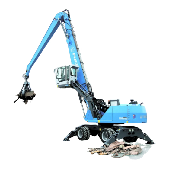
- Page 1 Operating Instructions BSB50000 Mobile hydraulic loading machine MHL360 E Vehicle ID no. starting 360310 / 4075-4200 Year of manufacture starting 2014 Version 17.07.2014 en (englisch) Original operating instructions...
- Page 2 Original EC Declaration of Conformity (Machinery Directive 2006/42/EC) Manufacturer: Terex® Deutschland GmbH Industriestrasse 3, 76669 Bad Schönborn, Germany Terex® Deutschland GmbH hereby declares that the machine named below General designation: Loading machine (developed from hydraulic excavator) Model/Type: MHL360 E Serial number: 360310/4075 >...
- Page 3 OVERVIEW OF CHAPTERS The TEREX | Fuchs operating instructions consist of 9 chapters intended for different target groups: Page No Theme Target group FOREWORD Operating staff Inspection and maintenance personnel Repair staff SAFETY AND ACCIDENT PREVENTION Operating staff Inspection and maintenance personnel...
-
Page 4: Table Of Contents
Safety instructions for replacing the (optional) XENON lamp ......... 2.18 2.6.3 Cleaning the machine .................... 2.20 2.6.4 Repairs on the machine ..................2.20 2.6.5 Electrical system ....................2.21 2.6.6 Hydroaccumulators ....................2.21 2.6.7 Hydraulic hoses and hose lines ................2.21 MHL360 E... - Page 5 O&K control system: Steering with a four-way control lever (optional) ....4.13 4.2.9 Liebherr control system: Steering with a four-way control lever (optional) ....4.14 4.2.10 Multifunction display ....................4.15 4.2.10.1 Structure ......................4.15 4.2.10.2 Display screens ....................4.15 4.2.10.3 Operating states ....................4.15 MHL360 E...
- Page 6 4.5.13.8 System information ................... 4.45 4.5.14 User settings (optional) ..................4.45 4.5.14.1 Reversing fan pause times (optional) ..............4.46 4.5.14.2 Set limits (optional) .................... 4.47 Operation ........................5.2 n Safety........................5.1 5.1.1 Protection function of the cab .................. 5.1 MHL360 E...
- Page 7 Supplementary heating (optional) ................5.25 Operating the headlights ....................5.27 5.9.1 Driving headlamps ....................5.27 5.9.2 loading equipment and cab roof working floodlights..........5.27 5.10 Operating the windshield wipers ................... 5.28 5.10.1 Switching on / off ....................5.28 MHL360 E...
- Page 8 Auto-idling system ....................5.62 5.19.8 Auto-idling system with automatic engine shutdown (optional) ......5.63 5.19.8.1 Operation ......................5.63 5.19.8.2 Switching engine shutdown on/off ..............5.64 5.19.8.2 Switching engine shutdown on/off ..............5.64 5.19.8.3 Switch the automatic idling system on/off ............5.64 MHL360 E...
- Page 9 Flat bed trailer loading ....................6.7 Maintenance and service ..................7.1 n Safety and environmental protection ................. 7.1 7.1.1 Safety rules ......................7.1 7.1.2 Safe working positions ..................... 7.2 7.1.2.1 Maintenance position ..................7.2 7.1.2.2 Upper carriage ....................7.2 MHL360 E...
- Page 10 Filling the grease container on the uppercarriage ..........7.26 7.5.3.1 Triggering an additional lubrication pulse ............7.27 7.5.3.2 Lubrication when lubricating pump is faulty ............7.27 7.5.4 Cab door ........................ 7.27 Monitoring, maintenance and inspection plans ............. 7.28 MHL360 E...
- Page 11 Venting the oscillating axle cylinders ..............7.57 7.7.14 Hydraulic system ....................7.58 7.7.14.1 Check hydraulic oil level ..................7.59 7.7.14.2 Changing hydraulic oil ..................7.59 7.7.14.3 Return filters...................... 7.61 7.7.14.4 Ventilation filter ....................7.62 7.7.14.5 Oil filter for grab (optional) ................. 7.63 MHL360 E...
- Page 12 Air conditioning system .................... 8.5 8.8.2 Supplementary heating .................... 8.5 Table of malfunctions ..................... 8.6 8.9.1 No steering ......................8.6 8.9.2 No brake pressure ....................8.6 8.9.3 Insufficient braking power ..................8.6 8.9.4 Parking brake cannot be released ................8.6 MHL360 E...
- Page 13 Faults in the electrical system .................. 8.9 8.9.16 Malfunctions in the magnet system ................ 8.10 8.9.17 Malfunctions in the central lubrication system ............8.10 8.9.18 Work attachments ....................8.10 Appendix ........................9.1 Arrangement of fuses ..................... 9.1 Conversion factors ......................9.4 MHL360 E...
- Page 15 Diesel engine and exhaust system................1.3 Environmental standards ....................1.4 Notes on using the operating instructions............... 1.4 1.7.1 References to pictures and items................1.4 1.7.2 Abbreviations and terms ..................1.4 Operating instructions provided by outside suppliers ............1.4 Copyright ........................1.4 MHL360 E MHL360 E...
-
Page 17: Foreword 1
Intended use turer. The loading machine MHL360 E is intended h Diesel engine operating instructions solely for work which is suited to the function of the machine and its work attachment. Such... -
Page 18: Misuse
Attention noncompliance with the manufacturer’s speci- fications is regarded as improper use. The TEREX | Fuchs can provide no warranty for modifications or attachments to equipment on manufacturer is not liable for any damage TEREX | Fuchs products which have not been resulting from such use. -
Page 19: Type Plates And Vehicle Identification Number
(3/1) and crank- case. Type plates for the exhaust system are located in the exhaust gas after-treatment area. h Diesel engine operating instructions B S B 5 0 0 7 3 Fig. 3 Diesel engine type plate MHL360 E... -
Page 20: Environmental Standards
If above-mentioned liquids seep into Copyright to these operating instructions is the ground, their escape must be stopped asserted by Terex Deutschland GmbH. These immediately and the liquid be bound with suit- operating instructions are intended for use by able binding agents. - Page 21 Cab which can be raised and moved forwards ............. 2.23 2.8.1 Cab protective grating .................... 2.23 Equipment and attachment parts ................. 2.24 2.9.1 Retrofitting an electric motor .................. 2.24 2.9.2 Additional devices (wireless, mobile, radio) ............2.24 MHL360 E MHL360 E...
-
Page 23: Safety And Accident Prevention 2
• Information on how to avoid a danger the danger. In an emergency: Procedures in the event that danger occurs. Safety information at various points All other safety-related information is simply marked with the safety symbol. Structure n Text MHL360 E... -
Page 24: Safety Signs And Color Symbols
Various symbols are used on the machine. These should be visible and legible at all times. 2.2.1 Locations on the machine 20 21 BSB51044 Fig. 4 Overview Decals under the engine hood Decals in the pressure accumulator area (under the cab lift mechanism and under the bottom plate of the cab) MHL360 E... - Page 25 SAFETY AND ACCIDENT PREVENTION 2 54 55 56 BSB51045 Fig. 5 Overview MHL360 E...
- Page 26 Tool manufacturer's documentation B SB 50932 Carrying capacity sign (only for Italy) Information about the maximum right and left carrying capacity on the dipperstick. h Chapter 3.2 n Working range of the machine S c h ild 0 0 9 MHL360 E...
- Page 27 4 6 8 0 0 (1 0 3 ,1 7 0 ) (1 4 7 ,7 0 0 ) M H L 3 8 0 6 7 0 0 0 B SB 50942 5 3 58 60 9 86 0 MHL360 E...
- Page 28 Chapter 5.1.4 Emergency exit and emergency hammer B SB 50934 Operating instructions location Indicates the storage location of the operating instructions. B SB 50935 Certification labels 1 All loading machines except Russia 2 For Russia only B SB 50947 MHL360 E...
- Page 29 Chapter 5.1.3 Emergency lowering of cab S c h ild 0 2 3 Information sign for emergency lowering Indicates effect of emergency lowering valve lever on cab movement. h Chapter 5.1.3 Emergency lowering of cab B SB 50940 MHL360 E...
- Page 30 Maintain a sufficient dis- drive train. Switch off the tance from the moving diesel engine before per- loading equipment and forming any maintenance grab. work. B SB 50905 B SB 50906 MHL360 E...
- Page 31 Depressurize the system before servicing hydroac- cumulators. No welding, attachment, or soldering work is permitted on hy- B SB 50922 B SB 50907 droaccumulators. Keep flames or other sources of heat at a sufficient distance from the hydroaccumula- tor. MHL360 E...
- Page 32 Only oper- ly lower the cab. 2. Use the ate the machine with the ascending and descending cab door closed. aids provided when enter- ing and leaving the cab. B SB 50918 B SB 50907 B SB 50908 2.10 MHL360 E...
-
Page 33: General
(these may be related to special equipment on your machine). Only persons explicitly authorized to do so may operate, maintain or repair the ma- chine. All such persons must be of the legal minimum age. MHL360 E 2.11... -
Page 34: Avoiding Crushing And Burns
Do not use any restraining devices such as cables or chains that are damaged or do not have sufficient carrying capacity. Wear safety gloves when working with wire ropes. 2.12 MHL360 E... -
Page 35: Avoiding Fire And Explosion
When driving the machine in an area where visibility is poor, a second person must be deployed to offer guidance and protection. Modifications to the machine undertaken by the operator must not limit the driver's visibil- ity. MHL360 E 2.13... -
Page 36: Putting The Machine Into Operation Safely
3 At a distance of 39.37 in: 392.00℉ Before starting, check all control lights and instruments to make certain they are work- ing properly, move all operating levers to the neutral gate and fold the left armrest down. 2.14 MHL360 E... -
Page 37: Safe Working With The Machine
Always select the lower travel speed range not cause an accident. before reaching the downward slope, never on it. Always turn on the light when visibility is poor or it is dark. Do not allow any passengers on the ma- chine. MHL360 E 2.15... -
Page 38: Parking The Machine Safely
Lock the machine, remove all keys and se- Close all cab and paneling doors. cure the machine against unauthorized use. Ensure no-one is on the machine during transport. 2.16 MHL360 E... -
Page 39: Towing The Machine Safely
Suitable attachment (load hooks should be chine away from a dangerous site for repair. used for loading machine MHL360 E) Check that all trailing and towing devices are safe and secure when pulling or towing. -
Page 40: Residual Risk
Let the lamp cool down first. tive gloves. Wear safety goggles and safety gloves Keep unauthorized persons well away from when changing the lamp. the machine during maintenance. If necessary, cordon off ample space for the maintenance area. 2.18 MHL360 E... - Page 41 ATTENTION In the event of continuing starting difficulties when switching on (flick- ering light), switch the XENON headlamp off immediately. Other- wise the electronics in the ballast might be damaged beyond repair. MHL360 E 2.19...
-
Page 42: Cleaning The Machine
- Lubricate all bearing points, bolt connec- tions and the slewing ring to force out any Only persons with specialist knowledge and water or cleaning agent that may have en- experience are permitted to perform work tered. on hydraulic equipment. 2.20 MHL360 E... -
Page 43: Electrical System
(or immediately if damage is suspected) for Protect the control units before arc welding. leaks and externally visible damage! Re- h Chapter 7.2.4 Welding place any damaged parts immediately! Spraying oil can cause injuries and/or fires. MHL360 E 2.21... - Page 44 - Hose coming loose from the fitting - Corrosion of the fitting which reduces functionality and stability - Exceeding of storage times and usage periods 2.22 MHL360 E...
-
Page 45: Lubricants, Coolants And Fuels
You should therefore keep your can be obtained from the manufacturer. hand on the door at all times when opening it. Make sure that the door snaps into place once it is open, to prevent it opening or clos- ing. MHL360 E 2.23... -
Page 46: Fops/Front Protective Roof Grating Conforming To Din En Iso 10262
Equipment and attachment parts Equipment and attachment parts from third- party manufacturers or those that have not been generally approved by TEREX | Fuchs for fitting or mounting must not be fitted to or mounted on the machine without the prior written consent of TEREX | Fuchs. - Page 47 3.3.1 Uppercarriage and undercarriage ................3.8 3.3.2 Work equipment 16.5 m and 18 m ................3.9 3.3.3 Loading equipment 18 m cranked ................3.10 Technical data ......................3.11 Equipment (optional) ....................3.13 Work attachments ......................3.14 MHL360 E MHL360 E...
-
Page 49: Technical Data 3
12 Rear axle (oscillating axle) with 9 Slewing ring with swing gear and 7 Dipperstick drum brakes (service brake) swing brake D Working equipment 13 Disk brake (parking brake) 8 Cactus grab 14 Variable speed hydraulic motor with two-stage manual transmission MHL360 E... -
Page 50: Working Range Of The Machine
Loading equipment: boom 8.9 m, dipperstick 7.0 m and cactus grab g range of the machin 3 6 0 - 1 6 ,5 m 3 6 0 - 0 5 6 0 - 5 1 0 Fig. 8 Working range diagram (16.5 m loading equipment) MHL360 E... -
Page 51: Table Of Carrying Capacity (16.5 M Loading Equipment)
10.9° (10.9°) 9.1° (9.1°) 7.5° (7.5°) 6.2° (6.2°) 5.0° (5.0°) 3.6° (3.6°) -4.5 not supported (7.5) (5.8) (4.8) (4.0) 4-pt supported 8.7° (8.7°) 7.4° (7.4°) 6.2° (6.2°) 5.0° (5.0°) Fig. 9 Carrying capacity table (16.5 m loading equipment) MHL360 E... -
Page 52: Working Range Diagram (18 M Loading Equipment)
Loading equipment: boom 9.7 m, dipperstick 7.8 m and cactus grab 3 6 0 - 1 8 m 3 6 0 - 0 5 6 0 - 5 11 Fig. 10 Working range diagram (18 m loading equipment) MHL360 E... -
Page 53: Table Of Carrying Capacity (18 M Loading Equipment)
(5.4) (4.4) (3.7) (3.1) (2.7) 4-pt supported 8.8° (8.8°) 7.6° (7.6°) 6.4° (6.4°) 5.4° (5.4°) 4.4° (4.4°) 3.4° (3.4°) not supported (4.4) (3.7) 4-pt supported 5.0° (5.0°) 4.1° (4.1°) Fig. 11 Carrying capacity table (18 m loading equipment) MHL360 E... -
Page 54: Working Range Diagram (18 M Loading Equipment Cranked)
Loading equipment: Boom offset 9.7 m, dipperstick 7.8 m and cactus grab 3 6 0 - 1 8 m g e k r 3 6 0 - 0 5 6 0 - 5 1 2 Fig. 12 Working range diagram (18 m loading equipment offset) MHL360 E... -
Page 55: Carrying Capacity Table (18 M Loading Equipment Cranked)
5.1° (5.1°) 4.2° (4.2°) not supported (9.3°) (6.7) (5.2) (4.2) (3.5) (3.0) (2.7) 4-pt supported 9.3° (9.3°) 8.9° (8.9°) 7.5° (7.5°) 6.3° (6.3°) 5.3° (5.3°) 4.4° (4.4°) 3.3° (3.3°) Fig. 13 Carrying capacity table (18 m loading equipment offset) MHL360 E... -
Page 56: Dimensions
1 9 6 0 3 0 0 0 3 3 1 - 1 4 1 0 - 5 0 1 3 6 0 - 0 5 6 0 - 5 0 1 Fig. 14 Dimensions (measurements in mm) with 12.00-24 tires MHL360 E... -
Page 57: Work Equipment 16.5 M And 18 M
1 Average center of gravity in transport position 2 Transport position with dozer blade (optional) TRANSPORT DIMENSIONS Dimensions in Loading equipment 16.5 m Loading equipment 18 m 13820 14610 1720 1720 6410 6440 3500 3500 3450 3740 2060 2060 1900 1900 MHL360 E... -
Page 58: Loading Equipment 18 M Cranked
• Since the steering movements are reversed when the uppercarriage is rotated, drive slowly and with care. In an emergency: Administer first aid, seek treatment from a doctor TRANSPORT DIMENSIONS Dimensions in Loading equipment 18 m cranked 14620 1720 5950 3500 3780 2060 1900 3.10 MHL360 E... -
Page 59: Technical Data 3
Slewing ring with inner gear teeth. Drive via plane- ing, driven directly by diesel engine via V-belts, tary gears. Integrated multi-disk brake, electrically for operation of the magnetic plates. activated. Uppercarriage swing speed: 0 – 6 rpm Swing range: 360° unrestricted Max. torque: 91 kNm MHL360 E 3.11... - Page 60 Machine functions that are reduced or shut down as a function of limit values that are exceeded. Control With ISO control unit as standard, others availa- ble as an option h Chapter 5.6.3 Checking the control unit 3.12 MHL360 E...
-
Page 61: Equipment (Optional)
Overload warning device for hoisting Dipperstick impact protection • • Limits for loading height and reach • Float switch • For details of additional accessories, please refer to the latest price/equipment list or con- tact the manufacturer. MHL360 E 3.13... -
Page 62: Work Attachments
3 TECHNICAL DATA Work attachments Documentation covering work attachments supplied by TEREX | Fuchs is part of the scope of supply of every work attachment. It includes: Operator's manual Replacement parts catalog 3.14 MHL360 E... - Page 63 Function menu ....................... 4.31 4.5.6 Rear view camera ....................4.32 4.5.7 Magnet system (optional) ..................4.33 4.5.7.1 Normal magnet system display with operating mode selection menu ....4.33 4.5.7.2 Comfort magnet system display ................ 4.34 4.5.8 Reversing fan (optional) ..................4.35 MHL360 E...
- Page 64 4.5.13.6 Grease lubrication system diagnostics .............. 4.43 4.5.13.7 Magnet system diagnostics ................4.44 4.5.13.8 System information ................... 4.45 4.5.14 User settings (optional) ..................4.45 4.5.14.1 Reversing fan pause times (optional) ..............4.46 4.5.14.2 Set limits (optional) .................... 4.47 Kapitel- 1: 3) MHL360 E MHL360 E...
-
Page 65: Display And Control Elements 4
Chapter 5: Operation. n Familiarize yourself thoroughly with the display and control elements before driving or starting work. Only operate the loading ma- chine if you understand the operating instruc- tions in their entirety. MHL360 E... -
Page 66: Display And Control Elements In The Cab
14 Fixed armrest 37 Radio, CD player (optional) System voltage is 24 V. 15 Multifunction button Information about voltage converters for 12 V are 16 Temperature control for lunchbox/bottle holder available from your dealer 17 12 V socket (optional) MHL360 E... - Page 67 DISPLAY AND CONTROL ELEMENTS 4 B S B 5 0 8 9 5 Fig. 18 Cab overview 81 Fire extinguisher (optional) 82 Windshield release lever 83 Skylight sunblind 84 Windshield sunblind 85 Skylight handle 86 Interior lighting 87 Emergency hammer MHL360 E...
-
Page 68: Four-Way Control Lever
Four-way control lever and direction of motion according to current control unit 90 Beam down 94 Extend dipperstick 91 Open grab 95 Swing uppercarriage clockwise 92 Beam up 96 Retract dipperstick 93 Close grab 97 Swing uppercarriage counterclockwise MHL360 E... -
Page 69: Control Panel
76 Pushbutton for front left outrigger leg (optional) 61 Flashing control indicator (right) 77 Pushbutton for rear right outrigger leg (optional) 62 Diesel particle filter regeneration indicator/button 78 Pushbutton for rear left outrigger leg (optional) toggle 63 Pushbutton for oscillating axle lock release MHL360 E... -
Page 70: Operating Concept
If the customer so wishes, the loading ma- chine may be equipped with a special control. Special control of the machine (if yes, please tick) B S B 5 0 8 5 4 h Additional operating instructions Fig. 22 Control scheme example MHL360 E... -
Page 71: Iso Control System
9 Retract dozer blade 22 Swing brake foot switch 10 Increasing the operating pressure 23 Extend tilting cylinder 11 Retract outrigger 24 Retract tilting cylinder 12 Extend outrigger 25 Service brake 13 Right indicator 26 Forwards/reverse travel Optional MHL360 E... -
Page 72: Fuchs Control System
9 Retract dozer blade 22 Swing brake foot switch 10 Increase the operating pressure 23 Extend tilting cylinder 11 Retract outrigger 24 Retract tilting cylinder 12 Extend outrigger 25 Service brake 13 Right indicator 26 Forwards/reverse travel Optional MHL360 E... -
Page 73: O&K Control System
9 Retract dozer blade 22 Swing brake foot switch 10 Increasing the operating pressure 23 Extend tilting cylinder 11 Retract the outrigger 24 Retract tilting cylinder 12 Extend the outrigger 25 Service brake 13 Indicate right 26 Forwards/reverse travel Optional MHL360 E... -
Page 74: Liebherr Control System
9 Retract dozer blade 22 Swing brake foot switch 10 Increase the operating pressure 23 Extend tilting cylinder 11 Retract outrigger 24 Retract tilting cylinder 12 Extend outrigger 25 Service brake 13 Right indicator 26 Forwards/reverse travel Optional 4.10 MHL360 E... -
Page 75: Iso Control System: Steering With A Four-Way Control Lever (Optional)
22 Swing brake foot switch 10 Increasing the operating pressure 23 Extend tilting cylinder 11 Retract outrigger 24 Retract tilting cylinder 12 Extend outrigger 25 Service brake 13 Right indicator 26 Forwards/reverse travel 27 Forwards/reverse travel Optional MHL360 E 4.11... -
Page 76: Fuchs Control System: Steering With A Four-Way Control Lever (Optional)
22 Swing brake foot switch 10 Increase the operating pressure 23 Extend tilting cylinder 11 Retract outrigger 24 Retract tilting cylinder 12 Extend outrigger 25 Service brake 13 Right indicator 26 Forwards/reverse travel 27 Forwards/reverse travel Optional 4.12 MHL360 E... -
Page 77: O&K Control System: Steering With A Four-Way Control Lever (Optional)
22 Swing brake foot switch 10 Increasing the operating pressure 23 Extend tilting cylinder 11 Retract the outrigger 24 Retract tilting cylinder 12 Extend the outrigger 25 Service brake 13 Indicate right 26 Forwards/reverse travel 27 Forwards/reverse travel Optional MHL360 E 4.13... -
Page 78: Liebherr Control System: Steering With A Four-Way Control Lever (Optional)
22 Swing brake foot switch 10 Increase the operating pressure 23 Extend tilting cylinder 11 Retract outrigger 24 Retract tilting cylinder 12 Extend outrigger 25 Service brake 13 Right indicator 26 Forwards/reverse travel 27 Forwards/reverse travel Optional 4.14 MHL360 E... -
Page 79: Multifunction Display
After the ignition is turned off, the display electronics switch to standby mode for 10 minutes. When the ignition is switched on, the functionalities are immediately available dur- ing this time. After 10 min, the display switch- es off automatically. MHL360 E 4.15... -
Page 80: Multifunction Button With Eco And Power Mode
4.2.11.3 Switch the mode functions Press buttons (33/1), (33/2), (33/3). ► The mode selected, e.g. ECO + is shown in the display. (Fig. 34). Buttons (33/4) and (33/5) do not have a func- tion on this loading machine. 4.16 MHL360 E... -
Page 81: Multifunction Button Functions
Keep the button pressed ► Selected function remains triggered As an example: Raise the cab Double click ► Leads from each deeper menu level to the main control display Rotating Navigate the display menu ► Setting, e.g. of speed ► MHL360 E 4.17... -
Page 82: Navigation And Input
In the example of the main control display (36/1) the focus is directly on the sensitive area for opening the function menu (36/2). Pressing the central button (36/5) would open it. 4.18 MHL360 E... -
Page 83: Focus And Multifunction Button
(38/5). Press the but- ton (38/4), to change the indicator. If the focus is on a sensitive area for set values, the button (38/4) changes the val- ues according to the direction of rotation. MHL360 E 4.19... -
Page 84: Exiting A Display Screen
Activating the sensitive area (39/1) or press- ing the button (38/4) twice exits the particu- lar display screen and jumps to the next higher level. BSB50756 Fig. 39 Exiting the display screen 4.20 MHL360 E... -
Page 85: Overview Multifunction Display - Menu Structure
Working headlamps • Comfort magnet system display Show and change op- • erating mode for mag- netiza- tion/demagnetization Show several operat- • ing messages for the magnet system ISO guard function test Fig. 40 Menu structure MHL360 E 4.21... - Page 86 6 Grease lubrication Standby brightness • system diagnostics specification 7 Magnet system diagnostics 9 Carry out lamp test ECU diagnostics 0 Back 1 DM1 DM1 0 Back Fig. 41 Menu structure 4.22 MHL360 E...
-
Page 87: Overview Of Symbols
B SB 50702 Indicator – boom float function – close range (optional) B SB 50689 B SB 50722 Indicator – oscillating axle unlocked B SB 50703 Indicator - shutdown of driving and working functions B SB 50704 MHL360 E 4.23... - Page 88 Indicator – height limitation active (op- tional) B SB 50711 Indicator – range limiting active (op- tional) B SB 50712 Not Used B SB 50713 Not Used B SB 50714 Indicator - note message text! B SB 50714 B SB 50715 4.24 MHL360 E...
-
Page 89: Function Menu
B SB 50723 Lower window section windshield wiper B SB 50727 Range limiting B SB 50733 Reduce setting value B SB 50738 Cab forward B SB 50728 Not Used B SB 50723 Flashing beacon B SB 50729 MHL360 E 4.25... -
Page 90: Main Control Display Screens
The date/time, operating hours, machine iden- tification, and speed of the diesel engine (op- tional) are displayed in area (46/7). The sensitive areas (46/1 and 3) are divided into buttons. The buttons are assigned im- portant functions and/or additional menus. 4.26 MHL360 E... - Page 91 Briefly press the button. ► The menu appears. Some functions can be configured. In order to open a configuration menu: Press the side function button or hold down ► the button (47/13) until the menu appears. MHL360 E 4.27...
-
Page 92: Speed And Fine Mode Menu
(0%...100%), it is not possible to start the diesel engine other than in idle mode! To set FINE MODE: Using the arrow key or the mini-joystick, ► move the focus in the FINE MODE (49/2) direction. Change the setting as described above. ► 4.28 MHL360 E... -
Page 93: Gear Shift
The current range is shown by the indicator (50/3). Operating note Briefly press the side function button next ► to the button (50/1). or multifunction button Navigate focus to button (50/1). ► Briefly press button. ► MHL360 E 4.29... -
Page 94: Operating Hours, Date, Time, Fuel Consumption
Briefly press button. ► Resetting a counter in the display (51/2): Press and hold the side function button ► next to the button (51/4). or multifunction button Navigate focus to button (51/4). ► Press and hold button. ► 4.30 MHL360 E... -
Page 95: Function Menu
Use the mini-joystick to navigate the focus ► to the desired button. Briefly press button. ► With functions that can be set, change the ► value by turning the button. Then briefly press the button again. h Description of the individual functions MHL360 E 4.31... -
Page 96: Rear View Camera
A R B E IT S H Y D R A U L IK IS T G E S P E R R T If the connection is made, the camera im- age appears. or multifunction button Navigate focus to button (54/1). ► B S B 5 0 6 1 9 Briefly press button. ► Fig. 57 Pending message 4.32 MHL360 E... -
Page 97: Magnet System (Optional)
(60/10). If required, you can use button (60/9) to initiate an ISO guard function test manually. If this fails, an error message will appear. Operating note h Chapter 5.20.1 Magnet system (optional) MHL360 E 4.33... -
Page 98: Comfort Magnet System Display
Red symbol, white background: Short 14 TORQUE circuit in connection line or magnetic 15 SPEED plate. 16 MCU CONTROL UNIT STATUS B SB 51158 17 Relative operating time (relative to three-minute interval) 18 Symbols 19 Information texts, error messages, action information 4.34 MHL360 E... -
Page 99: Reversing Fan (Optional)
The symbolized LED (64/2) appears. A re- versal of direction occurs, after that rever- sal occurs at the specified intervals. h Chapter 4.5.14.1 Reversing fan pause times (optional) or multifunction button Navigate focus to button (64/1). ► Briefly press button. ► MHL360 E 4.35... -
Page 100: Main Menu Display Screens
► User Settings BSB50555 Fig. 66 Main menu 0 Back 1 System information 2 Diagnostics menu 3 Service menu 4 Display settings 5 User settings 6 Not assigned 7 Not assigned 8 Not assigned 9 Not assigned 4.36 MHL360 E... -
Page 101: Display Settings
BSB51162 tion using the mini-joystick. Fig. 68 Controlling display settings Briefly press button. ► ATTENTION Selection of a different table cell or exiting the display screen is only possible once the table cell is no longer active. MHL360 E 4.37... -
Page 102: Service Menu
If the access code is correct, the service ► menu appears once the last digit has been entered. or multifunction button Navigate the focus to the button (69/2) with ► the desired number. Briefly press button. ► 4.38 MHL360 E... -
Page 103: Diagnostics Menu
This display screen indicates the status of the CAN1 I/O Extension BUS DIGNOSTIS components connected on the CANopen bus. Call-up NO COMMUNICATION Main control display > Main menu > Diag- ► MAIN CONTROLLER UNIT nostics menu > CANopen diagnostics BSB50623 Fig. 71 CANopen diagnostics MHL360 E 4.39... -
Page 104: Operating Hours
6 With the engine running, switch off the ignition (ser- vice engineers only) 7 Not in low idle (service engineers only) 8 LS pressure over 360 bar (service engineers only) 9 Load value over 100% (service engineers only) 4.40 MHL360 E... -
Page 105: Ecu Diagnostics
Number of Faults: Protection Lamp Status SPN-NO: Suspect Parameter Warning Lamp Status Number (SPN) Failure Mode Stop Lamp Status Identifier (FMI) O ccurence Emission Related Lamp Status Count (OC) BSB51052 Fig. 74 ECU diagnostics: DM1 (for Service personnel) MHL360 E 4.41... -
Page 106: Lmb/Hrb Diagnostics
The load pressure generated by the instanta- neous load is measured by a pressure sensor. The measured value is displayed as a per- centage of the load limit pressure with a bar graph (76/7). h Chapter 5.19 Important functions 4.42 MHL360 E... -
Page 107: Grease Lubrication System Diagnostics
5 Remaining pause time 6 Remaining pump run time 7 Achieved number of pump cycles with detector moni- toring 8 Status change detected 9 Number of pump cycles reached 10 Status of piston detector; HIGH= green LOW= gray MHL360 E 4.43... -
Page 108: Magnet System Diagnostics
0 [n ] 0 [n ] Torque Limitation [% ] OC Wa rning Count 0 [n ] Magne t Plate Wa rning Count 0 [n ] BSB51120 Fig. 83 Magnet system data, menu 2 (for service personnel) 4.44 MHL360 E... -
Page 109: System Information
And Reach Limits desired button (85/0-2). or multifunction button BSB50630 Navigate focus to button (85/0-2). ► Fig. 85 User settings Briefly press button. 0 Back ► 1 Set height and range limits 2 Reversing fan pause time MHL360 E 4.45... -
Page 110: Reversing Fan Pause Times (Optional)
To enter individual pause times Activate side button (86/1). ► The current pause time in minutes (86/3) is shown with a white background. Change the pause time using the arrow ► buttons of the 4-way rocker switch or the button. 4.46 MHL360 E... -
Page 111: Set Limits (Optional)
6 Taking the overhang of the hoses into account Briefly press side function key next to the ► desired button (87/1 or 2). or multifunction button Navigate the focus to the button (87/1 or ► Briefly press button. ► h Chapter 5.19 Important functions MHL360 E 4.47... - Page 113 Supplementary heating (optional) ................5.25 Operating the headlights ....................5.27 5.9.1 Driving headlamps ....................5.27 5.9.2 loading equipment and cab roof working floodlights..........5.27 5.10 Operating the windshield wipers ................... 5.28 5.10.1 Switching on / off ....................5.28 MHL360 E...
- Page 114 Auto-idling system ....................5.62 5.19.8 Auto-idling system with automatic engine shutdown (optional) ......5.63 5.19.9 Reversing fan mode (optional) ................5.66 5.19.10 Disabling travel and work functions ................ 5.68 5.19.11 Key switches (optional) ..................5.69 5.20 Additional equipment ....................5.70 MHL360 E...
- Page 115 Hydraulic fluid temperature ..................5.87 5.21.9 Hydraulic oil level ....................5.88 5.21.10 Hydraulic oil filter (main and auxiliary circuits) ............5.89 5.21.11 Diesel particle filter soot loading ................5.90 5.21.12 Bypassing the shutdown function ................5.91 MHL360 E MHL360 E...
-
Page 116: Operation
Knowledge of the en- tire chapter is necessary for an understanding of the associations. n Only operate the loading machine if you understand the operating instructions in their entirety. MHL360 E... -
Page 117: Safety
(91/1) or from outside with the ball valve (90/1). In order to adjust the cab again after lowering, the ball valves (91/1) and (90/1) must be re- turned to the shut-off position. BSB50603 Fig. 91 Internal emergency lowering MHL360 E... -
Page 118: Emergency Exit And Emergency Hammer
If the diesel engine is started, pending regeneration occurs even during idling. h Chapter 5.6.1 Checking the diesel parti- cle filter status Open all hoods. ► Perform checks. ► h Care and maintenance chapter MHL360 E... -
Page 119: Using Climbing Aids
Fig. 96 Cab door grab handles and control ele- Close cab door. To do this, first use the ► ments upper part of the handle (96/4) and then the handle (96/9). Check whether the door is securely closed. ► MHL360 E... - Page 120 Fig. 97 Cab door grab handles and control ele- Unbuckle seat belt and flip up left armrest ► ments (97/2). Exit the cab. n Be especially careful when ► going from platform (97/4) to step (95/3) and then to step (95/3). MHL360 E...
-
Page 121: Maintenance Ladder
If this is not done, travel and work functions are disabled. Unlock the door latch (99/4) by pressing in ► B S B 5 0 0 0 3 and close the maintenance door (99/3) Bild 99 Wartungsaufstieg ausgeklappt again. MHL360 E... -
Page 122: The Cab As Workplace
10 Handle for seat cushion adjustment (tilt) 11 Handle for seat depth adjustment (leg rest) 12 Handle for shock absorber Turn lever towards cab door: hard Turn lever upwards: medium Turn lever away from seat: soft 13 Armrest tilt 14 Headrest MHL360 E... - Page 123 Depress the pedal (102/8) with your foot ► and adjust the inclination angle as desired. BSB50596 Release pedal (102/8) and then release Fig. 102 Adjusting the steering column ► steering wheel. The steering column must latch into position. MHL360 E...
- Page 124 Use the two unlocking levers to move the ► windshield forward and lower it into the end position. Unfold both unlocking levers (105/1) such ► that the locking bolts (105/2) snap into the holders (105/3). The windshield is locked. MHL360 E...
- Page 125 B S B 5 11 9 4 available for reading the operating instruc- Fig. 108 Sunblinds tions. Switch the desired light on or off with the ► button toggle (92/3). B S B 5 11 9 3 Fig. 109 Interior lamp MHL360 E...
-
Page 126: Starting And Shutting Down The Diesel Engine
Chapter 5.8.5 Supplementary heating (optional) 5.10 MHL360 E... - Page 127 Indicators (112/16) and (112/17) must ap- pear. Indicator (112/11): Coolant still too hot. Indicator (112/14): Too little coolant. Note indicators (113/56) and (113/62). h Chapter 5.6.1 Checking the diesel parti- cle filter status MHL360 E 5.11...
- Page 128 No starting operation If the start/stop button (115/31) is pressed, but no starting operation is triggered, it may be deactivated. h Chapter 5.21 Monitoring the machine dur- ing operation BSB50588 Fig. 115 Starting the diesel engine 5.12 MHL360 E...
-
Page 129: Switching Off The Diesel Engine In A Controlled Manner
Fig. 116 Switching off the diesel engine the multifunction button (116/15). Only switch off immediately in an emergency. h Chapter 5.7.1 Specifying the diesel en- gine speed Turn the ignition key (116/29) to the "0" ► position. The diesel engine turns off automatically. MHL360 E 5.13... -
Page 130: After Starting
After the diesel engine is started, check ► indicators (117/37) and display (118/62). If regeneration is due to start shortly, check ► the coolant temperature. If the environment is not suitable for regeneration, find anoth- er location. 5.14 MHL360 E... - Page 131 If the ash content is too high, indicator (118/56) comes on. If this occurs, the diesel particle filter needs to be replaced immediately. h Chapter 7.7.1 Exhaust system with diesel particle filter MHL360 E 5.15...
-
Page 132: Carry Out Lamp Test
Press function key (120/9) and hold it. Fig. 120 Lamp test ► The various lighting elements are switched or multifunction button Using the mini-joystick, navigate the focus ► to the button (120/9). Press button and hold it. ► 5.16 MHL360 E... -
Page 133: Checking The Control Unit
Carefully operate the control elements indi- ► cated on the sign. h Chapter 5.13 Retracting or extending outrigger h Chapter 5.14 Locking or unlocking the oscillating axle h Chapter 5.15 Traveling h Chapter 5.16 Charging BSB50854 Fig. 122 Control sign (example) MHL360 E 5.17... -
Page 134: Warming Up The Loading Machine
Position the loading machine at the materi- ► al to be loaded. Specify diesel engine speed and FINE ► MODE for work task. h Chapter 5.7.1 Specifying the diesel en- gine speed Switch on supporting functions. ► 5.18 MHL360 E... -
Page 135: Setting The Diesel Engine Speed And Fine Mode
Auto-idling system not active Specified speed is approached immedi- ately B SB 50860 Auto-idling system active Specified speed is only approached after an hydraulic function has been activated B SB 50790 h Chapter 5.19.7 Auto-idling system MHL360 E 5.19... -
Page 136: Setting Fine Mode
(126/5). or four-way rocker switch Use the right/left arrow button (126/7) to ► navigate the focus to the FINE Mode indi- cator. Immediately set the desired value. To do ► this, press arrow key (126/8) up/down. 5.20 MHL360 E... -
Page 137: General Settings
Indicator on: Circulating air opera- tion If the cab windows fog up, switch off circulating air B SB 50831 Press button (127/89) according to status. ► B S B 5 11 9 9 Fig. 128 Outside air supply MHL360 E 5.21... -
Page 138: Heating
Switching the heater controller on Fig. 129 Lever for heating/air conditioning system The controller is switched back on with the ► plus button toggle (129/84). The digital display (129/85) indicates the value "lo". Set the desired temperature. ► 5.22 MHL360 E... -
Page 139: Air Conditioning
Fig. 130 Lever for air conditioning system j WARNING Danger of injury due to refriger- • Maintenance work on the air con- ditioning system must only be carried out by trained specialists. In an emergency: Administer first aid, seek treatment from a doctor MHL360 E 5.23... -
Page 140: Bottle Holder And Lunchbox Temperature Control
No temperature control If cooling is not wanted, slew the lever as ► far right as it will go. B S B 5 1 2 0 0 Fig. 131 Bottle holder and lunchbox 5.24 MHL360 E... -
Page 141: Supplementary Heating (Optional)
WARNING Poisoning and suffocation from exhaust gases • The heater must not be operated in enclosed spaces. In an emergency: Switch heating off. Move into fresh air immediately. Seek treatment from a doctor. MHL360 E 5.25... - Page 142 Insert battery isolator switch. ► Reproduce factory settings (see manufac- ► turer's documentation). Remove fuse for timer in the central elec- ► trical system and reinsert. Perform initial commissioning (see manu- ► facturer's documentation). 5.26 MHL360 E...
-
Page 143: Driving Headlamps
The roof headlamps must not be slewed too far such that they can- not be damaged by rainwater B S B 5 1 2 0 2 Fig. 136 Roof headlamps - slewing range 1 H3 headlamp 2 Xenon headlamp MHL360 E 5.27... -
Page 144: Operating The Windshield Wipers
Wiper water Press button down and hold it in order to ► wipe with wiper water. After the button is released, the wipers continue to wipe in the previously selected mode or stop a short time later. 5.28 MHL360 E... -
Page 145: Intermittent Wiping Preset
Using the arrow keys, navigate the focus to ► the upper (138/45) or optionally to the low- er windshield wiper (138/52). Select the interval time using the function ► key (138/46 or 53). MHL360 E 5.29... -
Page 146: Operating Signals
B SB 50853 Main control display > Function menu ► Function keys Press function key (140/2) briefly. ► or multifunction button Using the mini-joystick, navigate the focus ► to the rotating beacon (140/60). Briefly press button. ► 5.30 MHL360 E... -
Page 147: Positioning The Cab
Move cab only while the machine is station- ary. Before turning off the Machine Move cab back into home position (141/1). Activate the parking brake. Do not raise enlarged stabilizer plates (op- tional), lay them on the ground instead. MHL360 E 5.31... -
Page 148: Positioning The Cab
Main control display > Function menu. ► Using the mini-joystick, navigate the focus ► to the desired direction of travel (142/40, 47, 54, 61). Press button until the desired position is ► reached. BSB50601 Fig. 143 Moving the cab - control panel 5.32 MHL360 E... -
Page 149: Retracting Or Extending Outrigger
If, after the outrigger is extended, it is retracted somewhat for correction, the hydraulic pressure drops in the outrigger cylinder. Therefore, move the lever (144/2) slightly forward. Retract the outrigger Move lever (144/2) back until the outrigger ► is completely retracted. MHL360 E 5.33... -
Page 150: Individually Controlled Support (Optional)
Deselect all outrigger legs that are not ► needed. Only the indicators of the outrigger legs to be moved are still lit. Move lever (145/2) with a sensitive touch ► and correct the position of the loading ma- chine. 5.34 MHL360 E... -
Page 151: Locking Or Unlocking The Oscillating Axle
Fig. 148 Oscillating axle unlocked For the slewing and loading operations, lock oscillating axle. For travel operation (without load) unlock oscillating axle. Drive with a load only with the loading de- vice over the steering axle. MHL360 E 5.35... -
Page 152: Locking And Unlocking
(150/63) is switched on. Diesel engine is running. ► Press the button toggle (150/63) as need- ► BSB50955 BSB50963 Fig. 150 Oscillating axle unlocking 1 Steering axle 2 Oscillating axle unlocked 5.36 MHL360 E... -
Page 153: Traveling
Locking the oscillating axle. BSB50892 Fig. 153 Position of the loading device Align uppercarriage with lower carriage in the longitudinal direction. Maximum of five degrees deviation. Use the swing brake to secure the upper- carriage against turning. MHL360 E 5.37... - Page 154 Drive in such a way that the load does not swing out. Stopping Engage the parking brake while the ma- chine is stopped. When the parking brake is applied, the oscillating axle is automatically locked. 5.38 MHL360 E...
-
Page 155: Setting The Machine In Motion
Not for driving with load. B SB 50830 B SB 50837 B SB 50839 Function key Press function key (154/4) ► or multifunction button With the mini-joystick, navigate the focus to ► button (154/4). Briefly press button. ► MHL360 E 5.39... - Page 156 2 Oscillating axle Stopping Release accelerator pedal (155/10) or ► (155/11). The travel speed decreases until the load- ing machine stops. The hydraulic travel drive operates like a wear-free service brake. 5.40 MHL360 E...
-
Page 157: Fully Applied
Parking brake for parking the loading ma- Fig. 157 Braking chine. (157/63) (156/23) Parking brake Not active B SB 50758 B SB 50765 Engaged B SB 50759 B SB 50875 Press parking brake button toggle ► (157/54). MHL360 E 5.41... -
Page 158: Steering
• Do not traverse a slope. Do not park the machine on an incline. • The auto-idling system must be turned off when driving on in- clines. In an emergency: Administer first aid, seek treatment from a doctor 5.42 MHL360 E... -
Page 159: Charging
Do not turn the uppercarriage so fast that an excessive centrifugal force is produced. Brake in such a way that the load does not swing. Do not brake the rotary movement of the machine by allowing the loading equipment to drop. MHL360 E 5.43... -
Page 160: Positioning The Loading Machine
If possible extend the outrigger (160/2). ► The uppercarriage may then also be turned. If this is not possible, engage parking ► brake (160/54). The oscillating axle is au- tomatically locked. Align uppercarriage and, when stopped, secure with the swing brake (160/55). 5.44 MHL360 E... -
Page 161: Moving The Loading Equipment
Fuchs O&K BSB50954 Fig. 161 Assignment with ISO control system Liebherr 92 Beam up 90 Beam down 96 Retract dipperstick 94 Extend dipperstick Retract and extend dipperstick ISO Fuchs O&K Liebherr MHL360 E 5.45... -
Page 162: Turning And Braking The Uppercarriage
(163/55) or button toggle on the left-hand four-way control lever (163/44) or foot switch (163/5) (op- tional). BSB50955 BSB50961 Fig. 163 Locking uppercarriage 44 Swing brake button toggle 5 Swing brake foot switch (optional) 5.46 MHL360 E... - Page 163 97 Swing uppercarriage counterclockwise Press the four-way control lever in the op- ► posite direction. The uppercarriage decel- erates quickly and immediately turns in the opposite direction. Turning the uppercarriage ISO Fuchs O&K Liebherr MHL360 E 5.47...
-
Page 164: Operating The Grab
91 Open grab If the load is securely gripped, release the ► 93 Close grab four-way control lever if possible. 47 Swing grab clockwise 45 Swing grab counterclockwise Opening and closing ISO Fuchs O&K Liebherr 5.48 MHL360 E... -
Page 165: Hoisting (Optional)
Loading machines MHL360 E are only to be Prior to beginning work, the personnel at- used for hoisting if the safety equipment pre- taching the loads are to be informed of the... -
Page 166: Parking The Loading Machine
(167/55) on, or, alternatively, press the but- Fig. 167 Parking the machine ton toggle on the left-hand four-way control lever (167/44/). ATTENTION The swing brake is not a dynamic brake. Activate the "Swing brake" push-button only with the swing as- sembly at standstill! 5.50 MHL360 E... - Page 167 Turn the ignition key (167/29) to "0" and ► remove it. Fold up the left armrest (167/4). ► Lock the cab, as well as all windows and ► skylights, to prevent unauthorized access. Clean the machine at regular intervals. ► MHL360 E 5.51...
-
Page 168: Important Functions
Symbol Close range Actions Dipperstick No cut-off outside B SB 50765 Dipperstick Dipperstick retraction in close cut off range Indicator not flashing, color (1): orange, contin- B SB 50774 uous line Text message "STICK IS IN CLOSE RANGE" 5.52 MHL360 E... - Page 169 Dipperstick Indicator flashing, color outside (1): red, broken line Text message and func- tion as above B SB 50780 Carefully move dipperstick further. ► Deactivate close-range expansion as soon ► as possible via the button toggle (171/53). MHL360 E 5.53...
-
Page 170: Overload Warning Device For Hoisting (Optional)
(172/38) appears. Automatic reduction in loading machine power. B SB 51042 Overload warning device deactivat- ed. The key can no longer be removed. The symbol (172/38) does not appear, no acoustic/optical warning! No reduc- B SB 51041 tion in power. 5.54 MHL360 E... -
Page 171: Height Limitation (Optional)
Indicator not flashing, color (1): orange B SB 50768 Text message "LOADING DEVICE HAS 1800 U PM REACHED HEIGHT 95°C 75°C 10 15 20 25 LIMIT" MH LXXX / XXXX ½ 09:43 11.03.2011 BSB50666 Fig. 176 Height limit MHL360 E 5.55... - Page 172 Text message and func- tion as above B SB 50769 Switch to the main control display. ► Carefully move loading equipment further. ► Switch height limitation back to active as ► soon as possible in the function menu. 5.56 MHL360 E...
-
Page 173: Range Limiting (Optional)
Actions Loading de- None vice outside B SB 50765 Dipperstick Corresponding func- in the limit tion is switched off range Indicator not flashing, color (1): orange B SB 50763 Text message "LOADING DEVICE HAS REACHED RANGE LIMIT" MHL360 E 5.57... - Page 174 Text message and func- tion as above B SB 50764 Switch to the main control display. ► Carefully move loading equipment further. ► Switch range limitation back to active as ► soon as possible in the function menu. 5.58 MHL360 E...
-
Page 175: Boom Float Function (Optional)
► or 65). Use the button or central button to select or ► deselect. BSB51008 Fig. 185 Function menu or four-way control lever (change range only) On the right-hand four-way control lever, ► press button toggle (187/48). MHL360 E 5.59... - Page 176 Now, also operate and hold foot switch ► (187/5) and continue to work. Indicators (186/20) and text messages (186/34) indicate the interventions of the control unit. ATTENTION The control can be adjusted by authorized ser- vice personnel. 5.60 MHL360 E...
-
Page 177: Increasing The Operating Pressure
The pressure increase is effec- tive only for raising the boom and extending the dipperstick. Press button toggle (188/49) on the right ► four-way control lever and keep it held down. BSB50655 Fig. 188 Increasing the operating pressure MHL360 E 5.61... -
Page 178: Auto-Idling System
Using the mini-joystick, navigate the focus ► to the square (189/67). Briefly press button. ► The adjustment is saved even after restarting. ATTENTION When the magnet system is switched on (optional) the automatic idling sys- tem does not function 5.62 MHL360 E... -
Page 179: Auto-Idling System With Automatic Engine Shutdown (Optional)
Factory setting: 10 mins. Machine operator authorization Factory setting: The machine operator cannot turn off the auto-idling system with engine shutdown. ATTENTION After starting the diesel engine, the auto-idling system and engine shutdown are always switched on. MHL360 E 5.63... - Page 180 Information about access to the service menu: h Chapter 4.5.12 Service menu Adjusting the shutdown time Setting range: 1 Min. – 30 Mins. Factory setting: 10 Mins. Procedure Service menu > Settings ► Press the F7 (192) function key. ► 5.64 MHL360 E...
- Page 181 B S B 5 1 2 9 3 Factory setting: Machine operator cannot Bild 193 Deactivating engine shutdown switch off shutdown Procedure Service menu > Settings ► Press function key F8 (193/4) o change the ► setting. Exit the service menu. ► MHL360 E 5.65...
-
Page 182: Reversing Fan Mode (Optional)
Reversing in progress Indicator color (1): yellow, then green. If the text message "INCREASE ENGINE SPEED FOR FAN B SB 50800 REVERSING" appears, the reversal has taken place, but the required fan speed has not been reached. 5.66 MHL360 E... - Page 183 If it is changed, a reversal of direction occurs, after that reversal takes 60 min place at the new intervals. h Chapter 4.5.14.1 Reversing fan pause times (optional) BSB50592 Fig. 195 Reversing fan pause times MHL360 E 5.67...
-
Page 184: Disabling Travel And Work Functions
Enabled 09:43 11.03.2011 BSB50659 Fig. 196 Disabling travel and work functions B SB 50759 B SB 50765 Disabled Text message "WORKING HYDRAULICS DISABLED" B SB 50758 B SB 50879 BSB50660 Fig. 197 Disabling travel and work functions 5.68 MHL360 E... -
Page 185: Key Switches (Optional)
Fig. 198 Key switch draulic system by triggering another work movement. In the case of machines which are equipped with a dead man’s button on the left-hand four-way control lever (optional), also press the dead man's button. MHL360 E 5.69... -
Page 186: Additional Equipment
• If the ISO guard is initiated, lower the load immediately. Discontinue any operation of the magnet sys- tem. Have the problem corrected by the authorized service person- nel. In an emergency: Immediately seek treatment from or call a doctor. 5.70 MHL360 E... - Page 187 Please refer to the manufac- turer's specifications for the permissible value. Magnetic plates from Terex-Fuchs: 65% relative operating time. ATTENTION Excessively long operating times may result in damage to the mag- netic plate.
- Page 188 Can be switched on. BSB51163 Fig. 202 Display settings B SB 50802 7 Design/Color: Activates or deactivates the comfort If you have not already done so, start the magnet system display or changes its color ► diesel engine. 5.72 MHL360 E...
- Page 189 Switching off the magnet system Prerequisite: Magnetic plate demagnetized. Deactivate button (203/6) using function ► key or multifunction button. If the LED and symbol (203/27) go out, this means the magnet system is switched off. MHL360 E 5.73...
- Page 190 (204/6). Press the button and hold it until the mag- ► net system operating mode selection menu appears. With the mini-joystick, navigate the focus to ► the button with the desired operating mode. Briefly press button. ► 5.74 MHL360 E...
- Page 191 In an emergency: Administer first aid, seek treatment from a doctor Select jog mode. ► To pick up the material, press button toggle ► (207/43) and hold it down. To drop the material, release button toggle ► (207/43). MHL360 E 5.75...
- Page 192 Switching off the magnet system Prerequisite: Magnetic plate demagnetized. Deactivate button (208/6) using function ► key or multifunction button. If the LED goes out and the normal magnet system display appears, this means the mag- net system is switched off. 5.76 MHL360 E...
- Page 193 Multifunction button With the mini-joystick, navigate the focus to ► button (210/9). Briefly press the button repeatedly until the ► symbol for the required operating mode appears. MHL360 E 5.77...
- Page 194 In an emergency: Administer first aid, seek treatment from a doctor Select jog mode. ► To pick up the material, press button toggle ► (212/43) and hold it down. To drop the material, release button toggle ► (212/43). 5.78 MHL360 E...
-
Page 195: Dozer Blade (Optional)
Indicator (213/19) is not lit. Dozer blade stops. Lifting the dozer blade Press and hold button toggle (214/46) on ► the right four-way control lever until the de- sired position is reached. Indicator (213/19) is not lit. Dozer blade rises. MHL360 E 5.79... -
Page 196: Steering With A Four-Way Control Lever (Optional)
To disable working hydraulics and travel operation Remove weight from the driver's seat ► (stand up) To enable working hydraulics and travel operation Apply weight to the driver's seat (sit down) ► 5.80 MHL360 E... -
Page 197: Monitoring The Machine During Operation
(215/17) lights up, switch off the diesel engine imme- diately. BSB50638 Fig. 216 Control panel display 56 Diesel particle filter ash load 58 Error display of the engine control system 62 Regeneration of diesel particle filter MHL360 E 5.81... -
Page 198: Coolant Temperature
If the warning message is still present after ► 60 seconds, shut down diesel engine. Check the water/charge cooler for contam- ination. Clean if necessary. If the warning message persists, call for ► service personnel. 5.82 MHL360 E... -
Page 199: Coolant Level
Switch off the diesel engine as quickly as ► possible. Visual inspection for potential leaks. ► BSB50640 Fig. 220 Control panel display Top up coolant. ► 58 Error display of the engine control system If the warning message persists, call for ► service personnel. MHL360 E 5.83... -
Page 200: Oil Pressure
58 Error display of the engine control system curs Switch off the diesel engine as quickly as ► possible. Visual inspection for potential leaks. ► Top up engine oil ► If the warning message persists, call for ► service personnel. 5.84 MHL360 E... -
Page 201: Charge Air Temperature
► possible. Check the water/charge cooler for contam- ► ination. Clean if necessary. If the warning message persists, call for ► service personnel. BSB50640 Fig. 224 Control panel display 58 Error display of the engine control system MHL360 E 5.85... -
Page 202: Air Filter Differential Pressure
Switch off the diesel engine as quickly as ► possible. Drain the fuel pre-filter. ► If the warning message persists, call for ► service personnel. BSB50640 Fig. 226 Control panel display 58 Error display of the engine control system 5.86 MHL360 E... -
Page 203: Hydraulic Fluid Temperature
If the engine fails to cool down, switch off ► the diesel engine as quickly as possible. Check the hydraulic oil cooler for contami- ► nation. Clean if necessary. If the warning message persists, call for ► service personnel. MHL360 E 5.87... -
Page 204: Hydraulic Oil Level
Measures to be taken when a warning oc- curs Switch off the diesel engine as quickly as ► possible. Visual inspection for potential leaks. ► Top up hydraulic oil. ► If the warning message persists, call for ► service personnel. 5.88 MHL360 E... -
Page 205: Hydraulic Oil Filter (Main And Auxiliary Circuits)
Warning levels are reset Optical warning cancelled again Measures to be taken when a warning oc- curs h The machine can continue to be operated for a short time. Perform an oil filter change as quickly as ► possible. MHL360 E 5.89... -
Page 206: Diesel Particle Filter Soot Loading
Replace the diesel particle filter Measures to be taken when a warning oc- curs Perform a regeneration. ► If regeneration does not start, shut down ► diesel engine as quickly as possible. Inform diesel engine manufacturer. ► 5.90 MHL360 E... -
Page 207: Bypassing The Shutdown Function
To avoid damaging the diesel en- gine, the machine may only be moved short distances during by- passing. Protection is bypassed only for as long as the pushbutton (231/64) is held down. BSB50595 Figure 231 Shutdown bypassing MHL360 E 5.91... - Page 209 Recovery, loading and transport ................6.1 Towing the machine ....................... 6.1 6.1.1 Power shift gear ....................... 6.2 6.1.2 2-speed manual transmission .................. 6.4 Recovery of the machine ....................6.5 Loading with a crane ...................... 6.5 Flat bed trailer loading ....................6.7 MHL360 E MHL360 E...
-
Page 211: Recovery, Loading And Transport 6
In an emergency: Administer first aid, seek treatment from a doctor Before the machine can be towed, the 2- speed manual transmission and the parking brake must be disengaged. MHL360 E... - Page 212 Screw back the threaded pin (235/2) by ½ ► turn and tighten counter nut (235/3). Screw on the screw cap (235/1) hand-tight. ► B S B 5 0 0 6 5 Fig. 236 Brake pads MHL360 E...
- Page 213 Seal the hoses and connections on the ► transmission. Bind loosened hoses firmly to the undercarriage. Start the engine. ► The transmission is now pressureless and remains in neutral position with the engine running. After towing, the hoses must be reattached to the transmission. MHL360 E...
- Page 214 (240/5). B S B 5 0 0 6 5 Fig. 240 Brake pads Screw back the threaded pin (239/2) by ½ ► turn and tighten counter nut (239/3). Screw on the screw cap (239/1) hand-tight. ► MHL360 E...
-
Page 215: Recovery Of The Machine
Remove support feet from the outrigger ► legs. A hoisting device can be obtained from ► TEREX | Fuchs. The pins and fastening el- ements match the attachment of the out- rigger feet. Attach hoisting device (241/1) with the pins ►... - Page 216 Only use an ade- BSB50887 quately sized lifting harness. Fig. 242 Lifting the machine The ropes must be routed so that no dam- ► age is caused to the cab or lining. Carefully hoist the loading machine using ► the crane. MHL360 E...
-
Page 217: Flat Bed Trailer Loading
Always keep the loading equipment just above the loading surface. Carefully drive onto the ramp and continue onto the transport vehicle. After loading the machine on the flatbed ► trailer, secure the uppercarriage against turning (apply swing brake). MHL360 E... - Page 218 Exercise special caution when driving un- ► der electrical lines, bridges and going through tunnels. When unloading, proceed with the same ► caution as when loading. MHL360 E...
- Page 219 Inspection and maintenance work ................7.35 7.7.1 Exhaust system with diesel particle filter ..............7.35 7.7.2 Engine oil ....................... 7.35 7.7.3 Fuel system ......................7.38 7.7.4 Air cleaner ......................7.45 7.7.5 Cooling system ...................... 7.48 7.7.6 Checking and adjusting valve lash ................. 7.51 MHL360 E...
- Page 220 Preservation for temporary taking out of service ............ 7.79 7.9.2 During shutdown ....................7.79 7.9.3 After shutdown ....................... 7.79 7.9.4 Once the machine has been out of use for more than half a year ......7.79 7.10 Disposal ........................7.80 MHL360 E MHL360 E...
-
Page 221: Safety And Environmental Protection
Failure to do so may adversely affect our war- • No changes may be made to the ranty coverage. pressure accumulators (welding, drilling, forcing open, etc.). In an emergency: Administer first aid, seek treatment from a doctor MHL360 E... -
Page 222: Safe Working Positions
Fuel filter, fuel pre-filter Engine Oil Level Engine oil filters V-rib belt Hydraulic oil level Central lubrication system for uppercarriage Batteries Use the maintenance ladder to gain access. h Chapter 5.3 Using climbing aids MHL360 E... -
Page 223: Discharging Residual Pressure In The Hydraulic Circuit
5) Accelerator pedals (246/10) and (246/11) 6) Emergency lowering (246/1) for elevating 7) Lever (246/2) to extend/retract 4-point outrigger 8) Pushbutton (246/45) and (246/47) for grab rotation right/left 9) Button toggle (246/63) for oscillating axle lock release 10) Slow/fast transmission control (245/4) MHL360 E... -
Page 224: Battery Isolator Switch
B SB 51166 Fig. 248 Blue key switch filter loading on the main control display. Reactivate regeneration in good time. ATTENTION If regeneration does not take place, the diesel particle filter will be de- stroyed. MHL360 E... -
Page 225: General Information
Ask your TEREX | Fuchs dealer for an infor- ground. Suitable containers must mation leaflet specifying the scope and pro- be used to collect them. -
Page 226: Welding
► the immediate vicinity of the welding point. To connect the battery, proceed in the op- ► posite order. Do not switch the battery iso- BSB50052 lating switch back on until the end. Fig. 251 Central electrical system MHL360 E... -
Page 227: Crack Test On The Machine
This in any doubt, consult your dealer or a can result in cracks and loose connections, TEREX | Fuchs service engineer for advice especially on load-bearing parts. To maintain on how to proceed. operating safety, the machine must therefore be checked weekly for cracks, loose connec- tions and other visible damage. -
Page 228: Fuels, Lubricants And Coolants
To avoid resulting premature wear of hydraulic components, reduce the intervals between oil changes (or reduce the interval between taking oil samples). We recommend using a filter system for tools as an option in such cases. MHL360 E... -
Page 229: Filling Quantities
Window washwipe system 0.92 gal Water with win- dow detergent Attention The filling quantities specified in the filling quantities table are only approximate values. The level must be checked in the corresponding assembly after every oil change or refill. MHL360 E... -
Page 230: Specifications For Fuels, Lubricants And Coolants
JIS K 2204: HFRR max. 460 µm coolant Before using RME fuels (rape oil methyl ester), it is essential that you consult your responsible TEREX | Fuchs dealer for further details. h Engine manufacturer's operat- ing instructions Engine Engine oil Titan Cargo Maxx ≥... - Page 231 -20°C.) DIN 51,502 Alternative recommendation at lower operating temperatures down to -30°C: Renolit JP 1619 Molykote TTF 52 See also enclosed user information from Lincoln Ring gear of slewing joint: Supplied by central lubrication system MHL360 E 7.11...
-
Page 232: Alternative Recommendations For Other Temperature Ranges
Doing so may cause aggressive reactions which in turn could damage the hydraulic system. Before changing oils, please ask your local TEREX | Fuchs dealer for advice. Vegetable-based oils are not permitted be- cause of their unsuitable temperature re- sistance. 7.12... -
Page 233: Notes For Use In Winter
Before the cold time of the year begins, the level of antifreeze protection must be checked and if necessary adapted to the ambient tem- perature (for the mixing ratio see the diesel engine manufacturers operating instructions). The antifreeze level is factory-set to approx. - 35°C. MHL360 E 7.13... -
Page 234: Jobs Before Putting The Machine Into Operation
(253/1). If necessary, top up with oil until the level ► reaches the upper mark MAX. h Filling quantity, oil quantity and change intervals: Chapter 7.3 Fuels, lubricants and coolants Chapter 7.6.4 Maintenance and inspection plan 7.14 MHL360 E... -
Page 235: Fuel System
• Wear protective goggles and pro- tective gloves when filling the tank. In an emergency: Wash off diesel fuel. Administer first aid, seek treatment from a doctor. Open the pump (255/1). ► Fill the tank. ► MHL360 E 7.15... - Page 236 Close the drain valve (257/2) when only ► fuel flows out. Dispose of the collected water/fuel mixture ► properly. B S B 5 0 0 0 4 Fig 257 Draining water from the fuel pre-filter 7.16 MHL360 E...
- Page 237 Then check the coolant level again. When the machine is delivered, the coolant ► contains antifreeze protection to -35°C (corresponding to a mixture of about 45% antifreeze). Antifreeze should be added throughout the year every time the system is topped up. MHL360 E 7.17...
-
Page 238: Check Hydraulic Oil Level
If the oil level falls considerably below the bot- tom mark, the indicator (261/14) lights up. h Refilling process Chapter 7.7.14.2 Chang- ing hydraulic oil. h Chapter 5.21 Monitoring the machine dur- ing operation 7.18 MHL360 E... -
Page 239: Cleaning The Cooler
Place the machine on a washing surface ► equipped with an oil separator. Clean the machine with a high-pressure ► cleaner. After cleaning, bring the drive motor to op- ► erating temperature to dry out the cooler. MHL360 E 7.19... -
Page 240: Tires
BSB50012 Fig. 265 Wheel hub Switch off the engine. ► Remove checking plugs, check and top up ► oil if required. h Chapter 7.3 Fuels, lubricants and coolants Chapter 7.6.4 Maintenance and inspection plan 7.20 MHL360 E... -
Page 241: Electrical Equipment
7.4.8.1 Lighting and warning equipment Check the lighting equipment for proper ► functionality. Check the function of the LEDs and indica- ► tor lamps in the display. Check the warning equipment for proper ► functionality. MHL360 E 7.21... -
Page 242: Overview Of Lubricating Points
7 CARE AND MAINTENANCE Overview of lubricating points 3 6 0 - 0 5 6 0 - 5 1 8 Fig. 268 Overview of lubricating points 7.22 MHL360 E... - Page 243 • Before greasing the machine, apply the outriggers and lower the loading equipment (boom in hori- zontal position). • The grab must be lubricated separately as described in the operating instructions supplied with the grab. In an emergency: Administer first aid, seek treatment from a doctor MHL360 E 7.23...
- Page 244 1: lubricating points each per steering gear case 1: 1 lubricating point Steering Cylinder Cab door BSB50018 BSB50019 Fig. 270 Steering cylinder Fig. 272 Cab door 1: 2 lubricating points each per steering cylinder 1: Lock 2: Hinges 7.24 MHL360 E...
-
Page 245: Automatic Central Lubrication System For Uppercarriage, Loading Equipment And Work Attachment Mounting
Diagnostics for grease lubrication system (optional) The diagnostics function displays the operat- ing modes, parameters and current status for central grease lubrication. Pending error mes- sages can be reset. h Chapter 4.5.13.6 Grease lubrication sys- tem diagnostics MHL360 E 7.25... -
Page 246: Grab Spherical Plain Bearing
Fig. 275 Triggering an additional lubrication pulse may not change its consistency over time. Lu- bricating additives, such as molybdenum disul- fide, must not be mixed in. Additional lubrication may need to be trig- gered after filling to achieve complete venting. 7.26 MHL360 E... -
Page 247: Cab Door
Grease the door hinges and door locks regular- ly. It is essential to wear safety goggles and suitable protective clothing during maintenance work. MHL360 E 7.27... -
Page 248: Monitoring, Maintenance And Inspection Plans
Perform a test run, a functional test of the hydraulic system and a test job. — Perform a visual inspection for leaks on all pipes, hoses, cylinders, etc. — Check function of electrical indicating and warning elements, as well as the lighting 7.4.8 Observe specifications on the warranty transfer card — 7.28 MHL360 E... - Page 249 Check the function of the overload warning device (optional). 7.7.24 Lubricate the machine according to the overview of lubricating points. Check the central lubrication system and the lubricating points it supplies in terms of leaks, seating of the connections and the lubricant supply. MHL360 E 7.29...
-
Page 250: Weekly Tasks
Check function, condition and completeness of safety equipment. — Lubricate the machine according to overview of lubricating points Check the grease container fill level 7.5.3 Opening the dust ejector valve on the air filter 7.7.4 7.30 MHL360 E... -
Page 251: Maintenance And Inspection Plan
Engine monitoring, warning system (only by service personnel au- thorized by the engine manufacturer) General overhaul h The optimum point in time depends on the conditions of use on site and should occur after consulting with the responsible dealer. MHL360 E 7.31... - Page 252 To prevent the hydraulic components wearing prematurely as a result, the oil change intervals (and/or the intervals between oil samples) should be reduced. 7.32 MHL360 E...
- Page 253 Condition of steering and outrigger Condition of heater and air conditioning Change the filter material for the air filter (hot water heating) Replace the air filter insert for the supplementary heating The intervals should be shortened in dusty ambient conditions. MHL360 E 7.33...
- Page 254 Test run and test work Item General Lubricate the machine according to overview of lubricating points h Page No 7.5 Complete operating instructions are available in the machine and are legi- Initial inspection cards and return to TEREX | Fuchs 7.34 MHL360 E...
-
Page 255: Inspection And Maintenance Work
The oil must be between MIN and MAX on ► the oil-level dip-stick (277/2). If necessary, top up with oil until the level ► reaches the upper mark MAX. MHL360 E 7.35... - Page 256 Close the cap (277/1). ► Start the diesel engine and run at a low idle ► for approx. 2 minutes. Switch off the diesel engine. ► Check the oil level after approx. 15 minutes ► and top up if necessary. 7.36 MHL360 E...
- Page 257 With one more half turn, tighten the filter ► cartridge. Only start the engine if it contains suffi- ► cient oil. h Chapter 7.7.2.1 Checking the engine oil level After a trial run, check the engine oil filter ► for leaks. MHL360 E 7.37...
- Page 258 When refueling with the electrical tank filling pump, open the tank cover so no excess pres- sure can build up in the fuel tank! Do not allow the fuel tank to run empty, other- wise the fuel system will need to be vented. 7.38 MHL360 E...
- Page 259 Seal the intake adapter (281/2) with the cap (281/1). ATTENTION It is essential to use the cap, since the built-in non-return valve is not suitable for providing a long-term seal. Close the tank cover. ► MHL360 E 7.39...
- Page 260 Screw on the new fuel filter cartridges and ► tighten firmly by hand. Tighten the fuel filter cartridges another ½ ► turn. ATTENTION There is no need to vent the fuel system. After a trial run, check the fuel filter for ► leaks. 7.40 MHL360 E...
- Page 261 In an emergency: Administer first aid, seek treatment from a doctor ATTENTION Function of drain valve: press the control knob toward the valve body, then turn. Switch off the diesel engine. ► Open the filter cover vent plug (283/1). ► MHL360 E 7.41...
- Page 262 Vent the fuel prefilter. ► h Chapter 7.7.3.7 Venting the fuel system ATTENTION The starter is not to be operated for longer than 20 seconds. After starting the engine, check the fuel ► prefilter for leaks. 7.42 MHL360 E...
- Page 263 (283/2) on the fuel prefilter. Collect the water/fuel mixture that drains out in a suitable container. Close the drain valve (283/2) when only fuel flows out. Dispose of the collected water/fuel mixture properly. MHL360 E 7.43...
- Page 264 "I" or "0", and wait for at least 30 seconds before repeating the start-up procedure. ATTENTION Do not drive the diesel engine at full throttle right away. Drive with re- straint until the engine reaches op- erating temperature. 7.44 MHL360 E...
-
Page 265: Air Cleaner
The discharge slot on the dust emptying valve (288/5) should be opened by hand once a week to ensure it does not jam due to high relative humidity and dust. MHL360 E 7.45... - Page 266 Install the main cartridge by turning it ► slightly into the filter body. Check to make sure it is seated correctly. Install the cover with the dust emptying ► valve below and fasten the support brack- ets (288/1). 7.46 MHL360 E...
- Page 267 Fig. 290 Cleaning the main cartridge determined using a torch. 1 Maximum 5 bar compressed air ATTENTION Do not install damaged main car- tridges. The diesel engine can be damaged if dust is able to get into MHL360 E 7.47...
- Page 268 If necessary, tighten the clamping bracket bolts (288/4). 7.7.5 Cooling system The machine is equipped with separate cool- ers for combined water/charge air cooling and the hydraulic oil. 7.48 MHL360 E...
- Page 269 Open the vent point (292/1). ► Unscrew the protective cap from the drain ► valve (293/1). Screw the drain hose provided in the tool ► box onto the drain valve (293/1) and drain off the coolant. MHL360 E 7.49...
- Page 270 Check the tightness of the cooling system. ► BSB50611 Fig. 296 Coolant level ATTENTION coolant level indicator (296/14) lights up, bring the diesel engine to idle immediately and then turn it off. Check the coolant level and top up if necessary. 7.50 MHL360 E...
-
Page 271: Checking And Adjusting Valve Lash
Perform check using the operating instruc- tions of the diesel engine manufacturer. ATTENTION On belt drives with no tensioning pulley, use a gauge to check the belt tension. MHL360 E 7.51... - Page 272 Re- place defective idler pulleys immediately. BSB50031 BSB50822 Fig. 298 Routing the V-ribbed belt 1 Crankshaft 2 Idler pulley 3 Air conditioning compressor 4 Hexagon-head for socket wrench 5 Holes for locking pin 7.52 MHL360 E...
- Page 273 Slowly move the loading equipment a little and ro- tate the uppercarriage by three revolutions. Listen for any unusual noise from the pumps. Switch off the diesel engine and check the ► tightness of the hydraulic system. MHL360 E 7.53...
-
Page 274: Venting The Pilot Control
Tighten the ventilation valve and refit the ► dust cap. Vent the other three brakes as described. ► BSB50616 BSB50617 Fig. 302 Venting the brake 7.54 MHL360 E... -
Page 275: Venting The Parking Brake
Run the diesel engine at medium speed. ► Open the vent plug (303/1) on the parking ► brake. When hydraulic oil which is free from bub- ► bles flows out, close the vent plug (303/1). BSB50616 BSB50617 Fig. 304 Venting the parking brake MHL360 E 7.55... -
Page 276: Adjusting The Play Of The Parking Brake
Fig. 305 Adjusting the parking brake Screw the threaded pin (305/2) back by ► half a turn. Counter with nut (305/3). ► Screw on the screw cap (305/1) hand-tight. ► B S B 5 0 0 3 7 Fig. 306 Brake pads 7.56 MHL360 E... - Page 277 Open the vent plugs (309/1) one after the ► other, until hydraulic oil flows out that is free from bubbles. Close the vent plug (309/1). ► BSB50617 Fig. 308 Venting the oscillating axle cylinder BSB50038 Fig. 309 Oscillating axle cylinder vent plug MHL360 E 7.57...
-
Page 278: Hydraulic System
ATTENTION Absolute cleanliness is particularly important for the hydraulic system. Because of this, recommended in- tervals for replacing the return filter element, for cleaning the oil cooler and for oil changes must be ob- served. 7.58 MHL360 E... - Page 279 Danger of injury due to falling • Before topping up the hydraulic oil, make sure that suitable equipment for this purpose (e.g. a pedestal) is at hand. In an emergency: Administer first aid, seek treatment from a doctor MHL360 E 7.59...
- Page 280 Chapter 7.7.8 Venting the hydraulic pump Screw on the ventilation filter. ► Close the covers of the return filters and ► install the complete filter. 7.60 MHL360 E...
- Page 281 M H L - X X X X - 5 0 7 Fig. 313 Return filter Remove the return filter on the bow (313/6) ► from the hydraulic tank. Clean the O-ring (313/3) between the hy- ► draulic tank and the return filter cover. MHL360 E 7.61...
- Page 282 Replace as described in chapter 7.6.4 Maintenance and inspection plan. Remove the breather (314/1), replace it with a new filter and tighten such that it is hand-tight. ATTENTION Replace the ventilation filter if it has become contaminated by hydraulic oil mist. 7.62 MHL360 E...
- Page 283 ► When doing this, oil the threads, sealing surfaces on the cover and housing, as well as the seals with hydraulic oil. Screw in the cover. Tightening torque: ► 40+10 Nm Check the filter for leaks. ► MHL360 E 7.63...
- Page 284 Fasten the retaining fixture (317/2) once ► more with the fillister-head screw (317/1) and secure with Loctite "blue". M H L - X X X X - 5 0 8 Fig. 318 Direction of flow 7.64 MHL360 E...
-
Page 285: Changing Axle And Transmission Oil
Flush out the axle if necessary. ► Carefully close the drain plug (319/2). ► Fill with oil through the check and filler plug ► (319/1) up to the bottom edge of the bore. Carefully close the check and filler plug. ► MHL360 E 7.65... - Page 286 Rinse if required. ► Carefully close the drain plug. ► Fill with oil through the check and filler plug ► (321/1) up to the bottom edge of the open- ing. Carefully close the check and filler plug. ► 7.66 MHL360 E...
- Page 287 (322/3). Fill with oil up to the bottom edge of the ► bore through the check and filler plug (322/1). Check the oil level of the manual transmission again. Carefully close the check and filler plug. ► MHL360 E 7.67...
- Page 288 (324/1) onto the sealing surface (324/2). Seal the oil filler with the cover (323/2). ► BSB51018 Fig. 323 Swing gear B S B 5 0 0 4 6 Fig. 324 Swing gear oil level check 7.68 MHL360 E...
- Page 289 CARE AND MAINTENANCE 7 7.7.16 Slewing joint 7.7.16.1 Checking the secure fastening of the slewing joint BSB51017 Fig. 325 Tightening torque Item no. Tightening torque Item no. Tightening torque 85 Nm 900 Nm 195 Nm 900 Nm 195 Nm MHL360 E 7.69...
-
Page 290: Slip Ring Bodies (Optional)
(use a cleaning spray if necessary). Re- place worn out (eaten through) cable lugs and spray "Cramolin" contact spray on all slip ring elements. Set the housing in place and tighten each pinch nut to the same extent. 7.70 MHL360 E... - Page 291 M H L - N B X X - 3 3 0 Check that fuel lines and connections are ► not leaking. Check the air filter element for dirt. M H L - X X X X - 3 2 6 Fig. 329 Supplementary heating MHL360 E 7.71...
-
Page 292: Wiper Water
(330/3). A worn wiper blade should be re- placed from inside the cab. To do this, slide the windshield up and lock it. M H L - X X X X - 3 1 2 Fig. 331 Filler neck for fluid container 7.72 MHL360 E... -
Page 293: Batteries
When outside temperatures are low and ► when the loading machine is switched off for an extended period, check the battery voltage regularly. Charge the batteries in good time. MHL360 E 7.73... - Page 294 First connect the positive pole, then the ► negative pole. Ensure good contact to the terminal connections. Tighten the terminal screws hand-tight. Lubricate the assembled terminals with ► acid-free and acid-resistant grease (pole grease). Insert battery isolator switch. ► 7.74 MHL360 E...
-
Page 295: Angular Resolvers (Optional)
The coordinates must not jump around or remain stationary. Extend and set down the loading equip- ► ment on level ground (Fig. 335). The dis- played position may deviate from the work- ing range diagram by ±0.25 m. MHL360 E 7.75... -
Page 296: Overload Warning Device (Optional)
Chapter 4.5.13.5 LMB/HRB diagnostics Measure the load pressure for the rod end ► and base end at the designated measuring connections, and compare this with the display. The measured values may deviate from those on the display by ±5 bar. 7.76 MHL360 E... -
Page 297: Care And Cleaning
If the engine is cleaned with water or high- ► pressure jets, do not expose sensitive en- gine parts (e.g. the generator, cabling, oil pressure switch, etc.) directly to the jet. Do not aim water jets at exhaust gas and air cleaner openings. MHL360 E 7.77... -
Page 298: Rear View Camera
- Polishing cleaning agents, such as polishes or waxes Remove soiling with a soft, chemically un- treated and dry cloth. Microfiber cloths with- out chemical additives are recommended. If soiling is heavy, use a damp cloth. 7.78 MHL360 E... -
Page 299: Taking Out Of Service
Coat connections with pole grease. Seal off the air intake opening of the air ► cleaner system and the exhaust pipe open- ing. MHL360 E 7.79... -
Page 300: Disposal
Collect fuels, lubricants and cool- ants in suitable reservoirs. Do not allow them to seep into the ground or water! Give to an authorized waste disposal company to sort and dispose of in an environmentally- friendly manner. 7.80 MHL360 E... - Page 301 Hydraulic cylinders sustaining losses ............... 8.9 8.9.15 Faults in the electrical system .................. 8.9 8.9.16 Malfunctions in the magnet system ................ 8.10 8.9.17 Malfunctions in the central lubrication system ............8.10 8.9.18 Work attachments ....................8.10 MHL360 E MHL360 E...
-
Page 303: Troubleshooting
Analyze the cause of the malfunction and ► correct it immediately. If you contact your TEREX | Fuchs dealer ► or Customer Service, please describe the malfunction and all accompanying circum- stances as precisely as possible. Exact in-... -
Page 304: Diesel Engine
Chapter 5.16.3 Moving the loading equip- ment The machine can be equipped with hose rup- ture safety devices as an option which will keep the loading equipment in position if a hose or line breaks. Controlled lowering is possible. MHL360 E... -
Page 305: Emergency Control
MALFUNCTIONS 8 Emergency control The machine is equipped with an emergency control system. Please contact your dealer or a TEREX | Fuchs service engineer for more detailed information. j WARNING Danger of injury due to unex- pected machine movements. • You should only use emergency control to move the machine out of the danger zone. -
Page 306: Malfunctions In The Load Limit Sensing Control
(343/1 and 2) out from the contact position. Start the machine. The indicator will remain ► lit, but load limit sensing control has been taken out of operation (341/10). Carefully move the machine without over- ► loading the diesel engine. MHL360 E... -
Page 307: Heater And Air Conditioning Malfunctions
Switch heating off. ► Uncover vents. ► Switch heating on. ► Other malfunctions which cannot be reme- ► died by the operator must be checked and repaired by Customer Service only. MHL360 E... -
Page 308: Table Of Malfunctions
Check oil supply to pump and shut-off valve, repair or replace. Disc brake sticking. Check, repair. Parking brake valve defective. Check and repair or replace. Oil loss in parking brake system. Check, repair. Rotary transmission defective. Check, repair. MHL360 E... -
Page 309: No Driving Function
Internal damage to variable displacement Have the units replaced by a specialist. pump or engine. 8.9.7 Regeneration does not start Automatic regeneration switched off. Turn the blue key switch in the central electrical system into a vertical position. MHL360 E... -
Page 310: Loading Equipment Is Not Working
Top up hydraulic oil to mark on sight glass. Oil cooler dirty or damaged. Clean oil cooler, check and replace if neces- sary. Air in hydraulic system. Vent the pilot control. Tighten connections with engine off and system relieved of pressure. MHL360 E... -
Page 311: Hydraulic Oil Exceeds Max. Admissible Temperature
Check the generator (V-belt tension). Check the charge capacity of the batteries. Test starter functions. Check the connection and condition of the power and earthing cables. Have the function of the ignition lock checked and re- place if necessary. Check the battery isolator switch. MHL360 E... -
Page 312: Malfunctions In The Central Lubrication System
Grab not opening or closing, or opening and Check quick coupling, replace if necessary. closing too slowly. Grab not rotating. Check the quick coupling and the electrical connection between the microswitch and the solenoid valve. Check the fuses. 8.10 MHL360 E... - Page 313 CONTENTS Appendix ........................9.1 Arrangement of fuses ..................... 9.1 Conversion factors ......................9.4 MHL360 E MHL360 E...
- Page 315 15 A Terminal 15 Spark plug control unit F 29 Terminal 15 CR0232 sensors, lubrication system, fan control: hydrau- lic oil cooler, fan control: water-charge air cooler, air dif- ferential pressure switch, slewing F 30 Terminal 15 Multifunction display MHL360 E...
- Page 316 Terminal 15 Compressor, reversing fan mode F 64 10 A Terminal 15 Control, cab floor, CR0303, VBBo16 F 65 10 A Terminal 15 Control, cab floor, CR0303, VBBo15 F 66 15 A Terminal 15 Control, cab floor, CR0303, VBBo02 MHL360 E...
- Page 317 The following fuses are located in the distribution box in the engine compartment Fuse Function F1.1-Mega 125 A Terminal 30 F1.2-Mega 125 A Power relay K2 terminal 15 F1.3-Mega 1 A Reserve F1.4-Mega 150 A Generator B+ F1.5-Midi 60 A Burner, air pump MHL360 E...
- Page 318 1 m³ 1000 liters 35.31 ft³ = 61,020 inch³ 1 ft³ 28.32 liters 7.48135 gal = 1728 inch³ 0.2642 gallons (US) 0.2201 gallons (Brit.) 1 gallon (US) 3.785 liters 231 inch³ 1 gallon (Brit.) 4.544 liters 277 inch³ MHL360 E...
- Page 320 Hauptverwaltung / Verkauf / Kundendienst Head Office / Sales / After Sales Service Sièges Administratif / Vente / Service Après-Vente Terex Deutschland GmbH Terex Fuchs Division 76669 Bad Schönborn GERMANY Phone: ++49 (0) 72 53 / 84-0 Fax: ++49 (0) 72 53 / 84 411 Email: info@fuchs-terex.de...
Need help?
Do you have a question about the MHL360 E and is the answer not in the manual?
Questions and answers