
Related Manuals for Kramer VP-427X2


Summary of Contents for Kramer VP-427X2
- Page 1 USER MANwUAL MODEL: VP-427X2 4K HDBT/HDMI Receiver/Scaler P/N: 2900-301500 Rev 1 www.kramerAV.com...
-
Page 2: Table Of Contents
Configuring HDCP per Input/Output Managing EDID Adjusting the Audio Delay and Volume Configuring Automatic Switching Settings Defining CEC Functionality Controlling VP-427X2 via the RS-232 Terminal Block Connectors Managing Authentication Viewing About Page Upgrading Firmware USB Firmware Upgrade (USB Format FAT32) -
Page 3: Introduction
Kramer Electronics Ltd. Introduction Welcome to Kramer Electronics! Since 1981, Kramer Electronics has been providing a world of unique, creative, and affordable solutions to the vast range of problems that confront the video, audio, presentation, and broadcasting professional on a daily basis. In recent years, we... -
Page 4: Overview
European Advanced Recycling Network (EARN) and will cover any costs of treatment, recycling and recovery of waste Kramer Electronics branded equipment on arrival at the EARN facility. For details of Kramer’s recycling arrangements in your particular country go to our recycling pages at www.kramerav.com/il/quality/environment. -
Page 5: Typical Applications
• Any application where high quality conversion and switching of multiple and different video signals to graphical data signals is required for display or projection purposes. Controlling your VP-427X2 Control your VP-427X2 directly via the front panel push buttons (with on-screen menus, or: •... -
Page 6: Defining Vp-427X2 4K Hdbt/Hdmi Receiver/Scaler
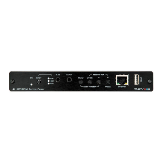
When not in OSD, press to freeze the display. ETHERNET RJ-45 Connect to a PC via a LAN to setup and monitor the VP-427X2, tunnel data Connector via HDBT, as well as upgrade the firmware. (Configured via web pages). - Page 7 Kramer Electronics Ltd. Figure 2: VP-427X2 4K HDBT/HDMI Receiver/Scaler Front Panel Feature Function INPUTS HDBT 1 RJ-45 Connector Connect to a transmitter (for example, the Kramer TP-780Txr HDBT 2 RJ-45 Connector Connect to a transmitter (for example, the Kramer TP-780Txr HDMI Connector Connect to an HDMI source.
-
Page 8: Mounting Vp-427X2
Kramer Electronics Ltd. Mounting VP-427X2 This section provides instructions for mounting VP-427X2. Before installing, verify that the environment is within the recommended range: • Operation temperature – 0 to 40C (32 to 104F). • Storage temperature – -40 to +70C (-40 to +158F). -
Page 9: Connecting Vp-427X2
Kramer Electronics Ltd. Connecting VP-427X2 Always switch off the power to each device before connecting it to your VP-427X2. After connecting your VP-427X2, connect its power and then switch on the power to each device. Figure 3: Connecting to the VP-427X2... -
Page 10: Connecting The Output To A Balanced/Unbalanced Stereo Audio Acceptor
Figure 4: Connecting to a Balanced Stereo Audio Figure 5: Connecting to an Unbalanced Stereo Audio Acceptor Acceptor Connecting to VP-427X2 via RS-232 You can connect to VP-427X2 via an RS-232 connection using, for example, a PC. VP-427X2 features an RS-232 3-pin terminal block connector allowing RS-232 control of VP-427X2. -
Page 11: Operating And Controlling Vp-427X2
(See Configuring TOGGLE Pin Behavior on page and/or Defining the TOGGLE Pin Behavior on page 35). Turn off the display (via CEC). Turn on the display (via CEC). VP-427X2 – Operating and Controlling VP-427X2... -
Page 12: Using The Osd Menu
Defining CEC on page 16. • Configuring TOGGLE Pin Behavior on page 17. • Defining HDBT Range on page 17. • Viewing Device Information on page 17. • Performing a Reset on page 18. VP-427X2 – Operating and Controlling VP-427X2... - Page 13 To set the input source: 1. On the front panel press MENU. The menu appears. 2. Click Input and select the Source: HDBT 1 (default), HDBT 2, or HDMI. An input signal is selected. VP-427X2 – Operating and Controlling VP-427X2...
- Page 14 2. Click Audio and define the following: ▪ Set the audio delay time (lip sync) to off, 40ms (default),110ms or 150ms. ▪ Set the AUDIO OUT output volume (default is 80 = 0dB). Audio parameters are defined. VP-427X2 – Operating and Controlling VP-427X2...
- Page 15 (3G), Def. 4K (3G - AUD), Def. 4K (6G), Def. 4K (6G - AUD) • The HDMI Output. • An external file (see Uploading EDID from an External File on page 14). The selected EDID is sent to the input. VP-427X2 – Operating and Controlling VP-427X2...
- Page 16 HDCP output to the HDCP setting of the acceptor to which it is connected. Select FOLLOW INPUT to change its HDCP output setting according to the HDCP of the input (recommended when the output is connected to a splitter/switcher). HDCP is set on the input/output. VP-427X2 – Operating and Controlling VP-427X2...
- Page 17 VP-427X2 enables defining the function of the FREEZE front panel button To define the FREEZE button operation mode: 1. On the front panel press MENU. The menu appears. 2. Click Advanced and select Freeze. VP-427X2 – Operating and Controlling VP-427X2...
- Page 18 ▪ On – Pass CEC commands from the source to the display. CEC functionality is defined. VP-427X2 – Operating and Controlling VP-427X2...
- Page 19 Device information includes the selected source, the input and output resolutions, and the software version. To view the information: 1. On the front panel press MENU. The menu appears. 2. Click INFO and view the input resolution, output resolution and software version. Information is displayed. VP-427X2 – Operating and Controlling VP-427X2...
-
Page 20: Operating Via Ethernet
3. Highlight the network adapter you want to use to connect to the device and click Change settings of this connection. The Local Area Connection Properties window for the selected network adapter appears as shown in Figure VP-427X2 – Operating and Controlling VP-427X2... - Page 21 (TCP/IPv4) depending on the requirements of your IT system. 5. Click Properties. The Internet Protocol Properties window relevant to your IT system appears as shown in Figure 7 Figure Figure 7: Internet Protocol Version 4 Properties Window VP-427X2 – Operating and Controlling VP-427X2...
- Page 22 You can connect the Ethernet port of VP-427X2 to the Ethernet port on a network hub or using a straight-through cable with RJ-45 connectors. Configuring Ethernet Port You can set the Ethernet parameters via the embedded Web pages. VP-427X2 – Operating and Controlling VP-427X2...
-
Page 23: Using Embedded Web Pages
29. • Configuring HDCP per Input/Output on page 30. • Managing EDID on page 31. • Adjusting the Audio Delay and Volume on page 33. • Configuring Automatic Switching Settings on page 34. VP-427X2 – Using Embedded Web Pages... -
Page 24: Loading And Saving Configurations
Kramer Electronics Ltd. • Defining CEC Functionality on page 35. • Controlling VP-427X2 via the RS-232 Terminal Block Connectors on page 36. • Managing Authentication on page 44. • Viewing About Page on page 46. To browse the VP-427X2 web pages: 1. -
Page 25: Entering Standby Mode
To toggle between standby mode and normal operation: • Click the power icon on the right-hand side of the web pages header. When in standby mode, the icon displays a gray background: Figure 11: VP-427X2 Standby Mode VP-427X2 – Using Embedded Web Pages... -
Page 26: Configuring Video Input Settings
2. In the Video Switching area, click the edit icon on the right side of the relevant video input. The settings window appears for the selected input. Figure 13: Setting Window for HDBT 1 Figure 14: Setting Window for HDMI VP-427X2 – Using Embedded Web Pages... -
Page 27: Selecting An Input
2. Use the slider controls in the Volume area of the web page to change the volume or enter the value in the text box above the slider. 3. Click to mute the output. Audio output volume is adjusted. VP-427X2 – Using Embedded Web Pages... -
Page 28: Viewing Device Details
1. Click Device Settings on the Navigation List. The Device Settings page appears. Figure 15: The Device Settings Page 2. Under Device Settings, view device details: Model, Device Name, Serial Number, MAC Address and Firmware Version. Device details are viewed. VP-427X2 – Using Embedded Web Pages... -
Page 29: Upgrading The Firmware
7. Re-enter the IP address and refresh the web page. 8. Make sure that the new version appears on the lower left side of the web page. Figure 18: Current Firmware Information Display Firmware upgrade is complete. VP-427X2 – Using Embedded Web Pages... -
Page 30: Configuring Network Settings
On check box and click Set changes. A confirmation message appears. 3. Click OK to confirm the change. The current web page session is disconnected. To access the web pages, reload with the new setting. Network settings are configured. VP-427X2 – Using Embedded Web Pages... -
Page 31: Performing Device Soft Factory Reset
HDBT and HDMI outputs. To configure video output settings: 1. Click Output Settings on the Navigation List. The Output Settings page appears. Figure 20: The Output Settings Page VP-427X2 – Using Embedded Web Pages... -
Page 32: Configuring Hdcp Per Input/Output
(even if the input does not include encryption). 3. In the On Input area, click ON or OFF for each of the inputs to turn on or off the HDCP encryption for that input. HDCP settings are defined. VP-427X2 – Using Embedded Web Pages... -
Page 33: Managing Edid
1. Click EDID on the Navigation List. The EDID page appears. Figure 22: The EDID Page 2. Under Read from, click the required EDID source or click Browse to use an EDID configuration File. VP-427X2 – Using Embedded Web Pages... - Page 34 4. Click Copy. The selected EDID is copied to the selected inputs and the Copy EDID Results message appears. Figure 24: The EDID Page – The Copy EDID Results 5. Click Close. EDID is copied. VP-427X2 – Using Embedded Web Pages...
-
Page 35: Adjusting The Audio Delay And Volume
2. For Delay, select a time value in milliseconds. 3. Use the slider controls or enter a number from 0 to 100 in the field to adjust the volume of the analog audio output. Audio settings are defined. VP-427X2 – Using Embedded Web Pages... -
Page 36: Configuring Automatic Switching Settings
Auto Scan – set auto-scanning. ▪ ▪ Last connected – when detecting that a source is connected to an input (which previously had no signal), automatically switch to that input. Auto Switching is defined. VP-427X2 – Using Embedded Web Pages... -
Page 37: Defining Cec Functionality
2. Select the TOGGLE pin configuration from the drop-down box: ▪ Edge = (toggle on/off). ▪ Input Select. ▪ GND=Off / Hi=On ▪ GND=On / Hi=Off ▪ Hi=Off ▪ Hi=On ▪ GND=Off ▪ GND=On TOGGLE pin button is defined. VP-427X2 – Using Embedded Web Pages... -
Page 38: Controlling Vp-427X2 Via The Rs-232 Terminal Block Connectors
Kramer Electronics Ltd. Controlling VP-427X2 via the RS-232 Terminal Block Connectors Configure the VP-427X2 RS-232 port to control the device, control an external device, or for tunneling of RS-232 commands via HDBT or via the Ethernet. Use the RS-232 CONTROL port to perform the following actions: •... - Page 39 Kramer Electronics Ltd. Controlling VP-427X2 via the RS-232 Port Connect the RS-232 port to a system controller to control the VP-427X2. To control VP-427X2 via RS-232: 1. Connect a controlling system to the RS-232 port (see Connecting to VP-427X2 via RS-232 on page 8).
- Page 40 To control an external device via RS-232 port: 1. Click RS-232 on the Navigation List. The RS-232 page appears. 2. Set “Use RS-232 Port for control of” drop-down box to External Control. Figure 30: RS-232 Page – Controlling an External Device VP-427X2 – Using Embedded Web Pages...
- Page 41 Click Delete to delete the command. ▪ Click Test to test the command. ▪ Change any of the command configurations. ▪ Enable or disable the command. Commands are sent to the display via VP-427X2 RS-232 port. VP-427X2 – Using Embedded Web Pages...
- Page 42 Figure 35: RS-232 Page – Controlling an External Device via Local Ethernet Tunneling 3. Set RS-232 Configuration parameters to enable communication with the display that is connected to the acceptor (or any other device with an RS-232 port), see Figure VP-427X2 – Using Embedded Web Pages...
- Page 43 HDBT (for example, HDBT 2) to VP-427X2 and fed to the RS-232 device connected to VP-427X2. Figure 36: External Device Control via HDBT Tunneling To control an external device via HDBT Tunneling to the RS-232 port: 1.
- Page 44 In this case, RS-232 terminal block connector is not operational. Figure 38: VP-427X2 Control via HDBT Tunneling To control VP-427X2 via HDBT Tunneling to the RS-232 port: 1. Click RS-232 on the Navigation List. The RS-232 page appears. 2. Set “Use RS-232 Port for control of” drop-down box to Scaler (HDBT2).
- Page 45 HDBT 1/HDBT 2 input. RS-232 commands are sent from the control system to the transmitter and tunneled via VP-427X2 HDBT (for example, HDBT 2) to the RS-232 device connected to VP-427X2. Figure 40: Ethernet Tunneling via HDBT RS-232 commands can be tunneled from the VP-427X2 Ethernet port to the RS-232 port that is connected to the external device.
-
Page 46: Managing Authentication
2. Check Authenticate Web Pages access to indicate that you want the web pages to lock. 3. Fill in a user name (the default is Admin). 4. Fill in a password (the default is Admin). VP-427X2 – Using Embedded Web Pages... - Page 47 Changing Password To change the password: 1. In the Navigation pane, click Authentication. The Authentication page appears. (Figure 42). 2. Enter the new Password. 3. Click Set changes. A confirmation message appears. Password has changed. VP-427X2 – Using Embedded Web Pages...
-
Page 48: Viewing About Page
Kramer Electronics Ltd. Viewing About Page View the Web page version and Kramer Electronics Ltd details in the About page. Figure 44: The About Page VP-427X2 – Using Embedded Web Pages... -
Page 49: Upgrading Firmware
Kramer Electronics Ltd. Upgrading Firmware Upgrade the firmware in any of the following ways: • Connecting the device to your PC and using Kramer K-UPLOAD software. • Via PROG USB port (see USB Firmware Upgrade (USB Format FAT32) on page 47). -
Page 50: Technical Specifications
115200 baud User Interface Control Input selection buttons, remote contact-closure switches. Kramer API via RS-232 serial commands transmitted by a PC, touch screen system or other serial controller, embedded web pages via LAN for configuration and control Indicators Power, link, input selection LEDs... -
Page 51: Default Communication Parameters
Additional descriptors... None Timing characteristics Horizontal scan range..15-136kHz Vertical scan range..23-61Hz Video bandwidth..600MHz CVT standard..... Not supported GTF standard..... Not supported Additional descriptors... None Preferred timing..Yes Native/preferred timing.. 3840x2160p at 60Hz (16:9) VP-427X2 – Technical Specifications... - Page 52 Rear LFE....No CE vendor specific data (VSDB) IEEE registration number. 0x000C03 CEC physical address..1.0.0.0 Supports AI (ACP, ISRC).. No Supports 48bpp... Yes Supports 36bpp... Yes Supports 30bpp... Yes Supports YCbCr 4:4:4..Yes Supports dual-link DVI... No VP-427X2 – Technical Specifications...
- Page 53 1280 x 1024p at 75Hz - VESA 1600 x 1200p at 60Hz - VESA STD 1280 x 1024p at 60Hz - VESA STD 1400 x 1050p at 60Hz - VESA STD 1920 x 1080p at 60Hz - VESA STD VP-427X2 – Technical Specifications...
- Page 54 Supports YCbCr 4:4:4..Yes Supports dual-link DVI... No Maximum TMDS clock..300MHz Audio/video latency (p).. n/a Audio/video latency (i).. n/a HDMI video capabilities.. Yes EDID screen size..No additional info 3D formats supported..Not supported Data payload..... 030C001000783C20008001020304 VP-427X2 – Technical Specifications...
-
Page 55: Protocol 3000
Kramer Electronics Ltd. Protocol 3000 Kramer devices can be operated using Kramer Protocol 3000 commands sent via serial or Ethernet ports. Understanding Protocol 3000 Protocol 3000 commands are a sequence of ASCII letters, structured according to the following. • Command format:... -
Page 56: Protocol 3000 Commands
– Safe mode safe_mode 0 – device accepts the EDID as is without trying to adjust 1 – device tries to adjust the EDID (default value if no parameter is sent) VP-427X2 – Protocol 3000... - Page 57 Get command list or COMMAND Get the command list: #HELP<CR> #HELP<CR> help for specific command command. #HELPcmd_name<CR> To get help for FEEDBACK AV-SW-TIMEOUT: 1. Multi-line: HELPav-sw-timeout<C ~nn@Devicecmd_name,cmd_name…<CR><LF> R> To get help for command use: HELP (COMMAND_NAME)<CR><LF> ~nn@HELPcmd_name:<CR><LF> description<CR><LF> USAGE:usage<CR><LF> VP-427X2 – Protocol 3000...
- Page 58 Reset machine (DNS) COMMAND Reset the machine name name to factory default. #NAME-RST<CR> (S/N last digits are 0102): #NAME- FEEDBACK Factory default of RSTkramer_0102<CR> ~nn@NAME-RSTok<CR><LF> machine (DNS) name is “KRAMER_” + 4 last digits of device serial number. VP-427X2 – Protocol 3000...
- Page 59 To avoid locking the FEEDBACK port due to a USB bug ~nn@RESETok<CR><LF> in Windows, disconnect USB connections immediately after running this command. If the port was locked, disconnect and reconnect the cable to reopen the port. VP-427X2 – Protocol 3000...
- Page 60 0 – Off #VFRZ1,1<CR> FEEDBACK 1 – On ~nn@VFRZout_index,freeze_flag<CR><LF> – 1 VFRZ? out_index Get output freeze COMMAND Get output freeze status: – On/Off status. freeze_flag #VFRZ?out_index<CR> #VFRZ?1<CR> 0 – Off FEEDBACK 1 – On ~nn@VFRZout_index,freeze_flag<CR><LF> VP-427X2 – Protocol 3000...
- Page 61 1 – Video disabled ~nn@VMUTEout_index,flag<CR><LF> – 1 out_index VMUTE? Get video on output COMMAND Get video on output status: – Video Mute status. flag #VMUTE?out_index<CR> #VMUTE?1<CR> 0 – Video enabled FEEDBACK 1 – Video disabled ~nn@VMUTEout_index,flag<CR><LF> VP-427X2 – Protocol 3000...
- Page 62 ▪ – Signal ID <signal_type> data if this capability is supported by the attribute: product. o VIDEO o AUDIO This is an Extended ▪ – 1 <index> Protocol 3000 state – OFF/ON (not case command. sensitive) VP-427X2 – Protocol 3000...
- Page 63 HDBT1=1 o HDBT2=2 o HDMI=1 ▪ – Signal ID <signal_type> attribute: o VIDEO ▪ <index> – 1 status – Input Signal Status 0 – No signal 1 – There is a signal VP-427X2 – Protocol 3000...
-
Page 64: Result And Error Codes
(Reserved) ERR_RESERVED_8 (Reserved) ERR_RESERVED_9 (Reserved) ERR_RESERVED_10 (Reserved) ERR_RESERVED_11 (Reserved) ERR_RESERVED_12 (Reserved) ERR_EDID_CORRUPTED EDID corrupted ERR_NON_LISTED Device specific errors File has the same CRC – not changed ERR_SAME_CRC ERR_WRONG_MODE Wrong operation mode ERR_NOT_CONFIGURED Device/chip was not initialized VP-427X2 – Protocol 3000... - Page 65 This limited warranty gives you specific legal rights, and you may have other rights which vary from country to country or state to state. This limited warranty is void if (i) the label bearing the serial number of this product has been removed or defaced, (ii) the product is not distributed by Kramer Electronics or (iii) this product is not purchased from an authorized Kramer Electronics reseller.
- Page 66 SAFETY WARNING Disconnect the unit from the power supply before opening and servicing For the latest information on our products and a list of Kramer distributors, visit our website where updates to this user manual may be found. We welcome your questions, comments, and feedback.
Need help?
Do you have a question about the VP-427X2 and is the answer not in the manual?
Questions and answers