Table of Contents
Advertisement
Quick Links
Advertisement
Table of Contents

Related Manuals for mangOH green


Summary of Contents for mangOH green
- Page 1 User Guide 4117164 Rev 2 Contents subject to change...
- Page 2 User Guide Important Due to the nature of wireless communications, transmission and reception of data can never be guaranteed. Data may be delayed, corrupted (i.e., have errors) or be totally Notice lost. Although significant delays or losses of data are rare when wireless devices such...
- Page 3 © 2016 Sierra Wireless. Licensed under the Creative Commons Attribution 4.0 license, http://creativecommons.org/licenses/by/4.0/ Disclaimer Indicate any modifications made to the original document. Trademarks mangOH™ and the mangOH logo are trademarks of Sierra Wireless. Other trademarks are the property of their respective owners. Revision History Revision Release date...
-
Page 4: Table Of Contents
Components and Accessories ........6... - Page 5 Contents Software Setup ............35 Install / Update Windows Driver.
-
Page 6: Introduction
1: Introduction This user guide explains how to set up and begin using the mangOH™ green with CF3 (Common Flexible Form Factor) modules. Once you have the mangOH green set up, visit mangoh.io for developer documentation, code samples, and other materials. - Page 7 It uses the dual SIM/SD connector. Audio cable (3.5 mm) Audio cable or headset Ethernet cable Ethernet cable (Cat5 or better) for use with the mangOH green’s 100 Mbps Ethernet connector Rev 2 Jan.16 4117164...
- Page 8 Battery Rechargeable Li-Ion or Li-Polymer battery (3V7 nominal) for use when USB/DC power supply is unavailable Arduino shields Plug-in boards for the mangOH green’s integrated Arduino Leonardo circuit Table 1-2: mangOH-compatible CF3 Modules Module series Notes AirPrime WP8548 The mangOH schematic (available at mango.io), describes all...
-
Page 9: Setup And Installation
Figure 2-1: Safe Handling Recommendations—CF3 Socket Locations (Do Not Touch) • Mount the mangOH green in a case, or attach standoffs (not included) to the mounting holes at each corner of the board to avoid damage to components on the bottom side of the board. -
Page 10: Initial Setup
Connect Antenna(s). See page 20. Install / Update Windows Driver. See page 35. 6. Connect the mangOH green to your computer using the USB cable provided. If you selected USB power in Step 2, the power LED lights up. 7. If you selected the DC power supply in... -
Page 11: Hardware Setup And Operation
3: Hardware Setup and Operation This chapter describes how to install various components on the mangOH green, and how to configure and control features using connectors and switches. Insert/Remove Embedded Modules The mangOH green has two CF3 module sockets •... - Page 12 User Guide 2. Hold the module above the socket and line up the polarity marks on the module and socket. (Primary module installation shown.) Figure 3-2: CF3 Module Positioning 3. Place the module onto the socket. The module should drop into place when you have it aligned properly.
- Page 13 Hardware Setup and Operation 4. Attach the module cover: a. Hold the module cover above the CF3 module and line up the polarity marks on the module and cover. Figure 3-4: Installing Module Cover b. Place the cover on the module, then press down carefully until you hear the cover click into place.
-
Page 14: Power Supply
Figure 3-6: Removing the Module Cover 3. Lift the cover off the module. 4. Carefully pinch the module and pull it straight up out of the socket. Power Supply The mangOH green has the following supplies: Table 3-1: mangOH green Power Supplies Supply Details... -
Page 15: Select Primary Power Supply
Hardware Setup and Operation Select Primary Power Supply To select the primary power supply: 1. Place the mangOH green face-up and locate the power supply jumper pins (CN1204). 1—Power supply select (CN1204) 2—DC jack 3—micro-USB connector (bottom side of board) Figure 3-7: Power Supply Select (CN1204) 2. -
Page 16: Connect Battery Backup
(DC or USB) fails. If a jumper is placed on CN1201, the mangOH green recharges the battery and then provides a trickle charge to maintain the battery’s full charge. -
Page 17: Rtc Capacitor
The capacitor can then be discharged by pressing this switch. 1—RTC capacitor (C346) 2—Discharge switch location (CN320) Figure 3-11: RTC Capacitor Insert SIM Card(s) The mangOH green supports dual SIM functionality (if supported by the CF3 module). Table 3-2: SIM connectors Type Connect Details... - Page 18 User Guide Note: A SIM card is not required if you want to connect to a LAN using the Ethernet port. To install the SIM card(s): 1. Place the Dev Kit face-down (as shown). 1—mini-SIM (CN801) 2—micro-SIM (CN802—bottom) 3—micro-SD (CN802—top)
-
Page 19: Insert Microsd Card
Hardware Setup and Operation Figure 3-14: SIMs—Inserted Insert microSD Card The mangOH green includes a microSD card slot in the top part of CN802. To install a microSD card: 1. Place the Dev Kit face-down (as shown). 1—mini-SIM (CN801) 2—micro-SIM (CN802—bottom) 3—micro-SD (CN802—top) -
Page 20: Connect Antenna(S)
User Guide Figure 3-16: microSD—Inserting Figure 3-17: microSD—Inserted Connect Antenna(s) The mangOH green includes three antenna ports for the primary CF3 module. Table 3-3: Antenna Ports Type Details Connector Main CN307 Required to establish a mobile network data connection Diversity CN304 Used only if primary CF3 supports diversity. - Page 21 Hardware Setup and Operation 1—Main (CN307) 2—GNSS (CN306) 3—Diversity (CN304) Figure 3-18: Antenna Connector Locations 2. Attach the antenna cable’s female connector to the board’s male connector and press firmly to get a secure connection. (Note that female connectors are rated for a limited number of reconnects before the connector wears out, so should be left connected if possible.
-
Page 22: Insert/Remove Iot Modules
ESD damage. To install an IoT module in any IoT slot: 1. Remove power from the mangOH green. (This step is recommended in case the IoT module is not hot-swappable or needs a reset.) 2. -
Page 23: Arduino Leonardo
1. Pull the module straight out, using safe ESD-handling practices (such as wearing proper ESD straps). For detailed interface information for each of the IoT slots, refer to the mangOH Developer’s Guide. For detailed information about IoT modules, refer to the IoT Module Specification. -
Page 24: Connect Arduino Shield
3-23, the ‘Bridge application’ is a Legato application (downloadable from legato.io) that allows communication between the CF3 module and the Arduino Leonardo. See the mangOH to Cloud Developer’s Guide for details. Connect Arduino Shield To connect an Arduino shield to the mangOH green: 1. -
Page 25: Audio Connection
Figure 3-26: Arduino Shield Installed on mangOH green Audio Connection The mangOH green includes a 3.5 mm audio jack for use with audio-enabled CF3 modules. If supported by the CF3 module, the jack can be used for making a voice call. -
Page 26: Ethernet Connection
User Guide 1—Audio jack (3.5mm) Figure 3-27: Audio Output Jack Ethernet Connection The mangOH green includes a 100 Mbps Ethernet port that may be used to connect the board to a LAN. 1—Ethernet port (100 Mbps) Figure 3-28: Ethernet Port The connector has two LEDs that exhibit the behavior described in the following table. -
Page 27: Usb Host Connection
1—Connection state LED 2—Connection speed LED Figure 3-29: Ethernet Port LEDs USB Host Connection The mangOH green includes a USB Host port (USB 2.0) for attaching a peripheral device, memory stick, etc. 1—USB Host port Figure 3-30: USB Host Port RS-232 Console Output Connection The mangOH green includes an RS-232 DB9 connector for console output. -
Page 28: Led Indicators
User Guide 1—RS-232 DB9 connector Figure 3-31: RS-232 Console Output Connection LED Indicators The mangOH green includes several LED indicators. Table 3-5: mangOH green LEDs Description 1—Power On when power is supplied by any power source (USB, DC, battery) 2—Arduino Rx... -
Page 29: Reset Switches
• Arduino reset (SW1500)—Press and hold for 5 seconds to reset the integrated Arduino Leonardo circuit. For details on resetting the mangOH green or specific application blocks, see the Developer’s Guide. Rev 2 Jan.16 4117164... -
Page 30: Mangoh Green Configuration
User Guide 1—Board reset (SW400) 2—Arduino reset (SW1500) Figure 3-33: Reset Switches mangOH green Configuration Default Configuration The mangOH green‘s default configuration is described in Table 3-6. Table 3-6: mangOH green Default Configuration Component / Default Configuration / Behavior... -
Page 31: Switch And Jumper Configuration Options
POWER_ON (Dip 1)=ON (Unit is enabled) Control • All others = OFF (SW401) Switch and Jumper Configuration Options The mangOH green uses several switches and jumpers to configure the board and CF3 module‘s operation, as detailed below in Table 3-7 through Table 3-9. - Page 32 User Guide Table 3-9: SW401—Module Signals Control (Continued) Signal On / Off State Reserved Off (Default) W_DISABLE_N Disable RF power for primary and secondary modules Off (Default) Enable RF power for primary and secondary modules SIM2_Detect No SIM detected...
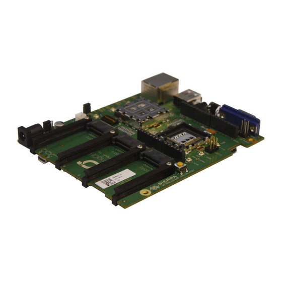
- Page 33 18—Arduino header 19—RTC backup capacitor 20—Secondary Main 21—Secondary GNSS 22—Secondary Diversity 23—Arduino header 24—Arduino reset 25—Secondary CF3 socket 26—Primary CF3 socket Figure 3-34: mangOH green Assembly—Top Side Switches/Connectors Note: For reference only. For latest schematic, visit mangoh.io. Rev 2 Jan.16 4117164...
- Page 34 User Guide 1—USB power 2—micro-SIM (bottom slot) 3—microSD (top slot) 4—mini-SIM 5—Arduino mini-USB Figure 3-35: mangOH green Assembly - Bottom Side Switches/Connectors Note: For reference only. For latest schematic, visit mangoh.io. Rev 2 Jan.16 4117164...
- Page 35 Windows driver and driver installation instruc- tions for your CF3 module. 2. Install the Windows driver. 3. When the mangOH green is connected via USB to the computer, display the Device Manager (Control Panel > System > Device Manager). Figure 4-1: Windows Device Manager If the driver installed correctly, you will see the following items listed: •...
- Page 36 Ports [COM & LPT] > Sierra Wireless NMEA Port (This is the port that you will use to communicate with the module from your terminal emulator.) Install a Terminal Emulator To communicate with the mangOH green, you need to use a terminal emulator ® program such as Tera Term or HyperTerminal...
- Page 37 Other Similar products are found below : Q52-DK XA1110-EVK FX30 DPY102223/5 BX3105 DEV KIT-6001182 XA1100-EVK XM1100-EVK MANGOH-GREEN-STARTER- KIT BX3100 DEV KIT-6001146 XA1110 DEV KIT-6001184 MANGOH-GREEN-BOARD-ONLY HL SNAP-IN TOOL WP8548_1103552 HL6528RD-2.8V 1103167 MC7430 WP7502 HL6528RD-G 1103166 WP SNAP-IN COVER WP8548 HL6528RD WP7504...
Need help?
Do you have a question about the green and is the answer not in the manual?
Questions and answers