Page 1
USER'S MANUAL 
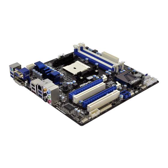
AMD A75 /A55 Chipset Based M/B for Socket FM1 AMD Processor NO. G03-A55M-F : Released in: October, 2011 Trademark: * Specifications and information contained in this documentation are furnished for information use only, and are subject to change at any time without notice, and should not be construed as a commitment by manufacturer.
Page 2
Environmental Safety Instruction Avoid the dusty, humidity and temperature extremes. Do not place the product in any area where it may become wet. 0 to 40 centigrade is the suitable temperature. (Actual figure depends on the request of the main chipset) Generally speaking, dramatic changes in temperature may lead to contact malfunction and crackles due to constant thermal expansion and contraction from the welding spots’...
CPU and GPU computing technology. It is designed to vastly improve today’s internet, video processing, playback and gaming experiences. AMD Radeon™ Dual Graphics The AMD™ Dual Graphics technology combines APU and GPU computing power to optimize user’s visual experience. ® ®...
Page 6
0 ~ 400MHz games, film television Normal load, APU to keep production and other heavy loads, APU low frequency energy automatic over clocking USB 3.0 (Optional for A75M series) Experience Fastest data transfers at 5Gb/s with USB3.0 the new latest connectivity standard. Built connect easily with nextgeneration components and peripherals, USB3.0 transfers data 10x faster and backward compatible with previous USB2.0 components.
USB 3.0 Ports ATX Power Conn. RJ-45 over USB 2.0 Ports Audio Connector PCI Express x16 by 16-lane Slot Megabit LAN Chip PCI Express x1 Slot AMD A75 Chipset SATAIII Hard Disk JBAT Ports PCI Slot (SATA1/2/3/4) USB 3.0 Header 6-CH...
Page 8
USB 2.0 Ports ATX Power Conn. RJ-45 over USB 2.0 Ports Audio Connector PCI Express x16 by 16-lane Slot Megabit LAN Chip PCI Express x1 Slot AMD A55 Chipset SATAII Hard Disk JBAT Ports PCI Slot (SATA1/2/3/4) 6-CH HD Audio Chip...
Chapter 2 Hardware Installation WARNING! Turn off your power when adding or removing expansion cards or other system components. Failure to do so may cause severe damage to both your motherboard and expansion cards. Hardware Installation Steps Before using your computer, you had better complete the following steps: 1.
2-3 CPU Installation 2-3-1 About AMD FM1 CPU Socket This motherboard provides an AMD FM1 socket. The CPU that comes with the motherboard should have a cooling FAN attached to prevent overheating. If this is not the case, then purchase a correct cooling FAN before you turn on your system.
6. Put the level to the 4. Open the socket by 5. Insert compatible APU original place of the pulling the level into APU socket and see socket. Make sure that to it that APU Pin-1 the notched corner sideways away from the should be matched into should point towards socket and then upwards...
DIMM1&DIMM2 Support Dual-Channel NOTE! When you install DIMM module fully into the DIMM socket the eject tabs should be locked into the DIMM module very firmly and fit into its indention on both sides. 2-5 Expansion Card Installation 2-5-1 Expansion Slots This series of boards offers one PCI-Express 2.0 x 16 by 16 lane graphics slot, one PCI Express 2.0 x1 slot and one 32-bit PCI slot to guarantee the rich connectivity for the I/O of peripherals.
Chapter 3 Connectors and Headers 3-1 I/O Back Panel Connectors RJ-45 LAN Port Optional PS/2 Mouse Line-In USB 2.0/ USB 3.0 Port Ports VGA Port DVI Port Line-Out HDMI Port PS/2 Keyboard Port MIC-In USB 2.0 Ports * Note: The above diagram is for illustration purpose only. Different models may differ in rear panel connectors.
3-2 Motherboard Internal Connectors (1) Power Connector (24-pin block): ATXPWR1 ATX Power Supply connector: This is a new defined 24-pin connector that usually comes with ATX case. The ATX Power Supply allows using soft power on momentary switch that connect from the front panel switch to 2-pins Power On jumper pole on the motherboard.
Page 15
(2) ATX 12V Power Connector (4-pin block): ATX12V2 This is a new defined 4-pins connector to provide extra 12V for system stability. Without this connector might cause system unstable because the power supply can not provide sufficient current for system. +12V +12V Pin1...
3-3 Headers (1) Line-Out/MIC Header for Front Panel (9-pin): AUDIO1 These headers connect to Front Panel Line-out, MIC connector with cable. AUDIO Pin 1 Line-Out, MIC Headers (2) USB 2.0 Port Headers (9-pin): USB1/USB2 These USB 2.0 headers are used for connecting the additional USB 2.0 port plugs.
Page 17
(6) Hard disk activity LED: HD LED This header connects to the hard disk activity indicator light on the case. (7) Reset switch: RESET This 2-pin header connects to the case-mounted reset switch for rebooting your computer without having to turn off your power switch. This is a preferred method of rebooting in order to prolong the lift of the system’s power supply.
Chapter 4 Useful Help 4-1 How to Update BIOS Solution1: Updating BIOS under DOS: 1. Prepare a bootable disk. (You may make one by click START click RUN type SYS click OK) 2. Download upgrade tools and the latest BIOS files of the motherboard from official website and then make a copy of it to your bootable floppy disk after decompressing these files 3.
Power Supply Mold As a result of the increasing power consumption demand from many AMD CPUs in current market, we suggest not to use a CPU that demands more than 65W power consumption at work for an AMD CPU compliant board that comes with power supply design as 3 phase or...
Page 20
Subject 2: Suggestion on choosing electric fan Both the amount of electric current to MOSFET and the heat produced from the motherboard go up as AMD’s CPU power consumption increases. In this case we recommend users select a CPU fan with air outlet towards MOSFET so that CPU fan can carry away heat produced by MOSFET, for better heat dissipation effects.