Advertisement
OWNER'S MANUAL
RD-8457E
Important:Read these instructions before installing, operating or servicing this product.
POSITIONING SYSTEM AND ACCESSORIES
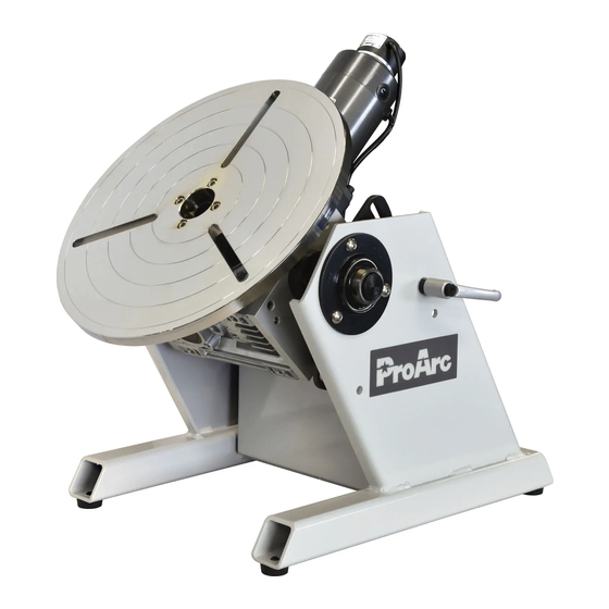
MODEL:PT‒103 / PT‒203
WELDING POSITIONERS
(With CB-101/CB-102)
Serial number:1808001 ~ and later
Date : Aug. 21, 2018
UNITED PROARC CORPORATION
th
No. 3 Gungye 10
Road, Pingjen Industrial Park,
Tel No:886 3 4696600
Pingjen City, Taoyuan 324, Taiwan
Fax No:886 3 4694499
http: //www.proarc.com.tw
E-Mail:
customerservice@proarc.com.tw
Advertisement

Related Manuals for ProArc PT-103


Summary of Contents for ProArc PT-103
- Page 1 MODEL:PT‒103 / PT‒203 WELDING POSITIONERS (With CB-101/CB-102) Serial number:1808001 ~ and later Date : Aug. 21, 2018 UNITED PROARC CORPORATION No. 3 Gungye 10 Road, Pingjen Industrial Park, Tel No:886 3 4696600 Pingjen City, Taoyuan 324, Taiwan Fax No:886 3 4694499 http:...
-
Page 3: Table Of Contents
Troubleshooting 3.1 Troubleshooting ....................7 Part list 4.1 Part List ‒ Mechanism (PT-103) ................. 9 4.2 Part List ‒ Mechanism (PT-203) ................ 11 4.3 Part List ‒ Control box (CB-101) ..............13 4.4 Part List ‒ Control box (CB-102) ..............14 Circuit diagram 5.1 Circuit Diagram .................... - Page 4 If there is any damage, notify the carrier immediately to file a claim. Furnish complete information concerning damage claims or mistake(s) in shipment to United ProArc Corporation: No. 3 Gungye10 Road, Pingjen Industrial Park, Pingjen City, Taoyuan 324, Taiwan. Include the equipment identification number along with a description of the parts in question.
-
Page 5: Safety Precautions
SAFETY PRECAUTIONS Operation and maintenance involves potential hazards. All operators and personnel should be alerted to possible hazards and precautions should be WARNING taken to prevent possible injury. Machine : Electrical safety ﹡ The counter, safety device against excess current and electrical installation, are compatible with its maximum power and its main voltage. - Page 6 SAFETY PRECAUTIONS ﹡ Gases and fumes produced during the plasma cutting or welding process can Gases and fumes be dangerous and hazardous to your health. ﹡ Ventilation must be adequate to remove gases and fumes during operation. ﹡ Keep all fumes and gases from the breathing area. ﹡...
-
Page 7: Limited Warranty
UNITED PROARC’s obligation under this warranty policy is expressly limited to the replace or repair, at its option, of the defected part only. ProArc’s option to repair or replacement of a defected part under this warranty shall be based on FOB Taiwan basis. - Page 8 1.1 GENERAL INFORMATION Features - Multiple selection of gear reducer for TIG, MAG/MIG welding application. - High frequency interference tested. - Tilting angle ranges from 0 ~120 - Faceplate through-hole Ø22mm for gas purge application. - Faceplate with 3 straight slots for 3-jaws fixture (PG-150,450L,500) mounting. - Control box selection:...
- Page 9 1.2 SPACIFICATION Model Unit PT-103 PT-203 Power input 1 Phase 100 ~ 240V 50/60Hz Capacity(Horizontal/Vertical) 100 / 60 200 / 130 Rated eccentricity A:180, B:90, C:60, D:45 A:84, B:42, C:28, D:10 ψ Table dimension (E) Rotation speed A:0.3 ~ 4 B:0.6 ~ 8 C:0.8 ~ 12 D:1 ~ 16 ψ...
- Page 10 2.1 CONTROL PANEL 1. Power On signal (LED) 2. CW/CCW selection switch. (SW1) 3. Weld / Test mode selection switch. (SW4) 4. Normal / Rapid speed selection switch. (SW3) 5. Work / Move mode selection switch. (SW2) 6. Stop button (STOP) 7.
-
Page 11: 2.2 Installation
2.2 INSTALLATION Power cord. Connect the power cord to 1 phase 100V~240VAC Note:The standard power connector is NEMA-5-15P, different region may select different power connector. NEMA-5-15P(Standard) European Adapter(Option) Australian Adapter(Option) Grounding Stud To avoid potential electrical damage, please connect the grounding stud to actual ground. ... - Page 12 2.3 OPERATION WORK / OFF/MOVE Toggle Switch (SW2) WORK:Enable the system in “WORK procedure” standby. Press/release the footswitch to start “WORK procedure”. Faceplate rotates according to timer VR1-VR4. OFF:Reset error and stop work procedure. MOVE:Enable the system in “MOVE” procedure standby. Press the footswitch to start the rotation, and release footswitch to stop the rotation.
-
Page 13: Timing Diagram
2.4 TIMING DIAGRAM (CB-102) - Page 14 3.1 TROUBLESHOOTING GUIDE SYMPTOMS POSSIBLE CAUSES / REMEDIES A. Blown fuse: Check the fuse, replace fuse when necessary. B. Input power switch malfunction : Check and replace the power switch. C. Check for any loose cable connection between Control Board and Power indicator LED does not Switch Board.
- Page 15 3.2 TROUBLESHOOTING GUIDE (CB-102) SYMPTOMS POSSIBLE CAUSES / REMEDIES A. Take VR Board JP2 connector off. Rotate the Start Delay knob and measure JP2 Pin 1 & 2’s resistance. The value should vary from 0-10kΩ. If there is no variation, check for any disconnection or Weld timer function no replace VR2.
- Page 16 4.1 PART LIST ― MECHANISM (PT-103) Item. Part No. Description Q’ty Remark 0312-0501 Shaft 5012-1150200-11 Reducer shaft 5112-1130000-10 Reducer fixing plate 0353-0332 Worm reducer 0351-0109 Gear reducer (15K) A:0.3~4 rpm 0351-0115 Gear reducer (7.5K) B:0.6~8 rpm 0351-0122 Gear reducer (5K) C:0.8~12 rpm...
- Page 17 4.1 PART LIST ― MECHANISM (PT-103)
-
Page 18: Part List - Mechanism (Pt-203)
4.2 PART LIST ― MECHANISM (PT-203) Item. Part No. Description Q’ty Remark 0312-0501 Bearing 5012-1150200-11 Reducer shaft 5112-1130000-10 Reducer fixing plate 0353-0332 Worm reducer 0351-0109 Gear reducer (15K) A:0.3~4 rpm 0351-0115 Gear reducer (7.5K) B:0.6~8 rpm 0351-0122 Gear reducer (5K) C:0.8~12 rpm 0351-0129 Gear reducer (3.6K) - Page 19 4.2 PART LIST ― MECHANISM (PT-203)
-
Page 20: Part List - Control Box (Cb-101)
4.3 PART LIST ― CONTROL BOX (CB-101) Item. Part No. Description Remark * 6622-1010 Printed circuit board Switch board * 3922-1210 Printed circuit board VR Board 3326-0008 Power supply * 6651-1110 Printed circuit board Motor speed control board 3545-5001 Grounding copper bar 3214-2009 Push button 3216-0006... -
Page 21: Part List - Control Box (Cb-102)
4.4 PART LIST ― CONTROL BOX (CB-102) Item. Part No. Description Qty. Remark * 6622-1010 Printed circuit board Switch board * 3922-1210 Printed circuit board VR Board 3326-0008 Power supply * 6651-1110 Printed circuit board Motor speed control board 3545-5001 Grounding copper bar 3214-2009 Push button... - Page 22 5.1 CIRCUIT DIGARM (CB-101/CB-102)
Need help?
Do you have a question about the PT-103 and is the answer not in the manual?
Questions and answers