Table of Contents
Advertisement
Quick Links
OWNER'S MANUAL
RD-8422E
Important:Read these instructions before installing, operating or servicing this product.
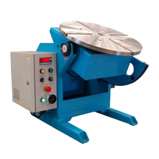
MODEL:PT–750 / PT–1500
WELDING POSITIONER
Serial Number:1307016 ~ and later
Date:Aug, 26, 2013
UNITED PROARC CORPORATION
th
No.3 Gungye 10
Road, Pingjen Industrial Park,
Tel No:886 3 4696600
Pingjen City, Taoyuan 324, Taiwan
Fax No:886 3 4694499
http: //www.proarc.com.tw
E-Mail: customerservice@proarc.com.tw
Advertisement
Table of Contents

Related Manuals for ProArc PT-750


Summary of Contents for ProArc PT-750
- Page 1 Important:Read these instructions before installing, operating or servicing this product. MODEL:PT–750 / PT–1500 WELDING POSITIONER Serial Number:1307016 ~ and later Date:Aug, 26, 2013 UNITED PROARC CORPORATION No.3 Gungye 10 Road, Pingjen Industrial Park, Tel No:886 3 4696600 Pingjen City, Taoyuan 324, Taiwan Fax No:886 3 4694499...
-
Page 3: Table Of Contents
3.1 Operation instruction .................. 4 3.2 Sequence diagram ..................5 Service 4.1 Trouble shooting guide ................6 5.1 Part List ‒ Machine (PT-750) ..............8 Parts list 5.2 Part List ‒ Machine (PT-1500) ..............10 5.3 Part List ‒ Ground ..................12 5.4 Part List ‒... - Page 4 If there is any damage, notify the carrier immediately to file a claim. Furnish complete information concerning damage claims or mistakes in shipment to United ProArc Corporation : No. 3 Gungye 10 Road, Pingjen Industrial Park, Pingjen City, Taoyuan 324, Taiwan. Include the quipment identification number along with a description of the parts in question.
-
Page 5: Safety Precautions
SAFETY PRECAUTIONS Operation and maintenance involve potential hazards. All operators and personnel should be alerted to possible hazards and precautions should WARNING be taken to prevent possible injury. Machine : Electrical safety ﹡ Terminate the main power on the external NFB. ﹡... -
Page 6: Limited Warranty
UNITED PROARC’s obligation under this warranty policy is expressly limited to the replace or repair, at its option, of the defected part only. ProArc’s option to repair or replacement of a defected part under this warranty shall be based on FOB Taiwan basis. -
Page 7: General Information 1.1 Introduction
1.1 INTRODUCTION ﹡ Welding positioned is normally used in the rotating and welding of the pipe or round Instruction work pieces. ﹡ It can be applied on all kinds of welding: SMAW, MIG, TIG, Plasma, etc. ﹡ It can adopt different fixture to get the welding effects you require. ﹡... -
Page 8: Specifications
1.2 SPECIFICATION MODEL UNIT PT-750 PT-1500 Power input 1 Phase 220V 50/60Hz Rated capacity NFB capacity Capacity(Horizontal / Vertical) 750 / 500 1,500 Rated center of gravity Rated eccentricity Table diameter Rotation speed 0.05~1 0.05~1 Spindle thru hole Ear thing Tilt range deg. -
Page 9: Maintenance 2.1 Maintenance
2.1 MAINTENANCE ﹡ Routine maintenance After using the machine, make sure to turn off the input main power to prevent the leakage of the electricity. ﹡ To make sure the function of the machine could work well for a long time, please keep clean all around the machine and the switch from the oil pollution. -
Page 10: Operation Instruction 3.1 Operation Instruction
3.1 OPERATION INSTRUCTION 1. Rotary’s power switch:System’s control power switch . 2. “Start” switch (Power):Turn ON the main power switch, press the control power switch ( power light ) to start operation. 3. Tilt direction switch (Down):Press button to move down direction; release to stop. 4. -
Page 11: Sequence Diagram
3.2 SEQUENCE DIAGRAM... -
Page 12: Service 4.1 Trouble Shooting Guide
4.1 TROUBLE SHOOTING GUIDE SYMPTOM POSSIBLE C AUSE/ REMEDY A. NFB jumps off. Check main circuit for any disconnection or short. B. No power input. Inspect the AC power input voltage. C. Power supply no DC24V output. 1. Inspect and make sure the switching power supply AC 1. - Page 13 4.1 TROUBLE SHOOTING GUIDE SYMPTOM POSSIBLE C AUSE/ REMEDY A. Tilt direction switch breaks down. Check / replace a new switch. B. Failed control PC board. Please refer to symptom No. 2. C. Inverter breaks down, no output. Please refer to symptom Nos. 3 & 4. D.
-
Page 14: Parts List 5.1 Part List - Machine (Pt-750)
5.1 PARTS LIST – MACHINE ( PT – 750 ) Fig. No. Part No. Description Qty. Remark 0127-0002 T – nut Rotation–Gear 5014-1020000-10 * 0305-1001 Bearing 0305-0801 Bearing 5014-1030000-20 Rotation – Drive pinion * 0353-0102 Worm reducer * 0350-0023 Motor reducer 5014-1090000-10 Home limited bracket 0120-0004... - Page 15 5.1 PARTS LIST – MACHINE ( PT – 750 )
-
Page 16: Part List - Machine (Pt-1500)
5.2 PARTS LIST – MACHINE( PT – 1500 ) Fig. No. Part No. Description Qty. Remark * 0127-0001 T – Nut 5015-1020000-10 Rotation – Gear * 0305-1101 Bearing 5015-1060000-10 Rotation – Spacer 0120-0005 Precision lock – Nut 5015-1030000-20 Rotation – drive pinion 5015-1070000-10 Rotation –... - Page 17 5.2 PARTS LIST – MACHINE( PT – 1500 )
-
Page 18: Part List - Ground
5.3 PARTS LIST ‒ GROUND (PT-750) Fig. No. Part No. Description Qty. Remark * 5010-2050102-10 Carbon brush * 5010-2040100-20 PE plastic body * 0144-0028 Spring 0106-0803 Hex cap screws (cupper) 0121-0804 Washer (cupper) * 4000-039046 Terminal 0123-0802 Nut (cupper) * 5015-3080020-21... - Page 19 5.3 PARTS LIST ‒ GROUND (PT-1500) Fig. No. Part No. Description Qty. Remark * 5010-2050102-10 Carbon brush * 5010-2040400-10 PE plastic body 5010-2040500-10 PE plastic body * 0144-0028 Spring * 4000-039046 Terminal 0106-0803 Hex cap screws (cupper) 0121-0804 Washer (cupper) 0123-0802 Nut (cupper) * 5015-3080000-21...
-
Page 20: Part List - Control Box
5.4 PARTS LIST – CONTROL BOX Fig. No. Part No. Description Qty. Remark 3221-2003 No Fuse breaker NFB (PT-750) 3323-0002 Power supply * 6652-1121 PC Board 3332-1201 EMI filter RF (PT-750/1500) * 3224-1005 Magnetic contactor ** 3021-2002 Inverter INV2 (PT-750) - Page 21 5.4 PARTS LIST ‐ CONTROL BOX...
-
Page 22: Diagram 6.1 Control System Box
6.1 CONTROL SYSTEM BOX... -
Page 23: Main Circuit
6.2 MAIN CIRCUIT... -
Page 24: Remote Control Circuit
6.3 REMOTE CONTROL CIRCUIT... -
Page 25: Inside Input / Output Connect Interface
6.4 INSIDE INPUT/OUTPUT CONNECT INTERFACE:PCB1 J1 CONNECTOR POWER SUPPLY DESCRIPTION 220V-L 220V-N DC24V DC0V J3 CONNECTOR INVERTER CTL DESCRIPTION INV1-F1 INV1-F2 INV2-B1 INV2-B2 FAN1 FAN2 CN1 CONNECTOR INVERTER 2 DESCRIPTION CN2 CONNECTOR INVERTER 2 DESCRIPTION +10V CN3 CONNECTOR INVERTER 1 DESCRIPTION... - Page 26 6.4 INSIDE INPUT/OUTPUT CONNECT INTERFACE:PCB1 CN4 CONNECTOR INVERTER 1 DESCRIPTION +10V CN6 CONNECTOR WELD OUTPUT DESCRIPTION SW1-1 R1-2 CN7 CONNECTOR HAND PENDANT DESCRIPTION AFM1 GND1 AVI1-HP 10V1 GND1 M10-HP ES-1 ES-2...
- Page 27 6.4 INSIDE INPUT/OUTPUT CONNECT INTERFACE:PCB1 CN8 CONNECTOR REMOTE FOOT SWITCH DESCRIPTION GND1 GND1 M10-RF GND1 CN9 CONNECTOR LIMIT SW DESCRIPTION LS-DN1 LS-DN2 LS-UP1 LS-UP2 CN10 CONNECTOR FRONT SW DESCRIPTION PB1-1 PB1-2 L1-1 L1-2 SW1-1 SW1-2 SW2-1 SW2-2 CN11 CONNECTOR DESCRIPTION MC-A1 MC-A2 MC-C1...
-
Page 28: Input / Output Connect Interface
6.5 INPUT/OUTPUT CONNECT INTERFACE CONTROL BOX JN1 CONNECTOR PCB-CN6 DESCRIPTION SW1-1 R1-2 JN2 CONNECTOR PCB-J3 DESCRIPTION INV1-F1 INF1-F2 JN3 CONNECTOR PCB-J3 DESCRIPTION INV2-B1 INF2-B2... - Page 29 6.5 INPUT/OUTPUT CONNECT INTERFACE CONTROL BOX JN4 CONNECTOR PCB-CN7 DESCRIPTION AFM1 GND1 AVI1-HP 10V1 GND1 M10-HP ES-1 ES-2 JN5 CONNECTOR PCB-CN8 DESCRIPTION GND1 M10-RF GND1 GND1...
-
Page 30: Appendix A:rotation Parameter Settings
Appendix A:ROTATION PARAMETER SETTINGS Inverter Table Setting Value Item. Name PT-750 PT-1500 Pr.00 Source of frequency command Pr.01 Source of operation command Pr.03 Maximum output frequency Pr.04 Maximum voltage frequency Pr.05 Maximum output voltage Pr.06 Mid-Point frequency Pr.07 Mid-Point voltage Pr.08... -
Page 31: B:tilt Parameter Settings
Appendix B:TILT PARAMETER SETTINGS Inverter Tilt Setting Value Item Group 1:User parameter PT-750 PT-1500 1-00 Maximum output frequency (Fo. Max) 1-01 Maximum voltage frequency 60.0 1-02 Max. Output voltage (Vmax) 1-03 Mid-Point frequency (Fmid) 1-04 Mid-Point Voltage (Vmid) 1-05 Minimum output frequency (F min) -
Page 34: Revised Revision
REVISION Manual Number Print Data Changed Page Revisions RD-8422E Aug. 26, 2013 RD-8422E Nov. 30, 2016 5.2 (P10) Revised No.13:5015-2110000-10→5014-2250000-21 Revised No.16:5015-2060000-10→5015-2060000-20 5.3 (P12) Adding Part No.8:5015-3080020-21 (PT-750) 5.3 (P13) Adding Part No.9:5015-3080000-21 (PT-1500)
Need help?
Do you have a question about the PT-750 and is the answer not in the manual?
Questions and answers