Table of Contents
Advertisement
Quick Links
Advertisement
Table of Contents

Related Manuals for KTM 890 Adventure R US 2021


Summary of Contents for KTM 890 Adventure R US 2021
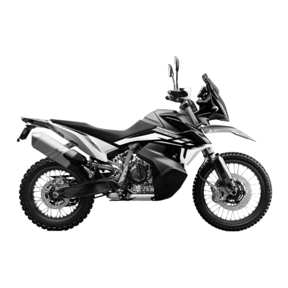
- Page 1 OWNER'S MANUAL 2021 890 ADVENTURE R 890 ADVENTURE R RALLY Art. no. 3214270en...
- Page 3 KTM accepts no liability for delivery options, deviations from fig- ures and descriptions, misprints, and other errors. The models portrayed partly contain special equipment that does not belong to the regular scope of supply.
- Page 4 Reproduction, even in part, as well as copying of all kinds, is permitted only with the express written permission of the copyright owner. ISO 9001(12 100 6061) KTM applies quality assurance processes that lead to the highest possible product quality as defined in the ISO 9001 international quality management standard. Issued by: TÜV Management Service KTM Sportmotorcycle GmbH Stallhofnerstraße 3...
-
Page 5: Table Of Contents
TABLE OF CONTENTS IMPORTANT NOTES........30 TABLE OF CONTENTS MEANS OF REPRESENTATION ....11 Manufacturer warranty, implied Symbols used ........11 warranty.......... 30 Formats used........12 Fuel, auxiliary substances ....30 SAFETY ADVICE.......... 13 Spare parts, technical accessories ..30 Use definition –... - Page 6 TABLE OF CONTENTS Hand brake lever......41 6.15 Opening the storage compartment on the right.......... 59 Throttle grip ........42 Switches on the left side of the 6.16 Closing the storage compartment on handlebar........42 the right.......... 60 6.17 Tool set........... 61 6.4.1 Combination switch......
- Page 7 Heating Seat Rider (function 7.25 Navigation display......92 optional) ........122 7.26 Menu..........93 7.26.25 Quick Shift+ (optional) ....123 7.26.1 KTM MY RIDE ......93 7.26.26 Settings ........123 7.26.2 Audio ......... 94 7.26.27 Favorites ........124 7.26.3 Navigation........96 7.26.28...
- Page 8 TABLE OF CONTENTS 7.26.37 DRL ......... 134 Adjusting the basic position of the foot brake lever ......153 7.26.38 Units ........136 7.26.39 Distance ........136 Checking the basic position of the shift lever........155 7.26.40 Temperature......137 Adjusting the basic position of the 7.26.41 Fuel Cons........
- Page 9 TABLE OF CONTENTS 11 SERVICE SCHEDULE ........ 183 12.10 Adjusting the spring preload of the shock absorber ......203 11.1 Additional information ....183 11.2 Required work ....... 183 13 SERVICE WORK ON THE CHASSIS..... 207 11.3 Recommended work ....... 186 13.1 Raising the motorcycle with rear lifting gear ........
- Page 10 TABLE OF CONTENTS 13.18 Removing left fuel tank spoiler ..228 14.3 Checking the front brake fluid level ..........266 13.19 Installing the left fuel tank spoiler ... 231 13.20 Removing right fuel tank spoiler ..233 14.4 Adding front brake fluid ....
- Page 11 TABLE OF CONTENTS 16.2 Removing the 12-V battery ..306 18.4 Throttle Response (optional) ... 338 16.3 Installing the 12-V battery ... 310 19 SERVICE WORK ON THE ENGINE ....339 16.4 Charging the 12-V battery ... 313 19.1 Checking the engine oil level... 339 16.5 Changing the main fuse ....
- Page 12 TABLE OF CONTENTS 23.3 Capacities ........367 29 LIST OF ABBREVIATIONS......398 23.3.1 Engine oil ......... 367 30 LIST OF SYMBOLS........399 23.3.2 Coolant ........367 30.1 Red symbols........399 23.3.3 Fuel ......... 367 30.2 Yellow and orange symbols....399 23.4 Chassis .........
-
Page 13: Means Of Representation 1
All work marked with this symbol requires specialist knowledge and technical understanding. In the interest of your own safety, have these jobs performed by an authorized KTM workshop! Your motorcycle will be optimally cared for there by specially trained experts using the auxiliary tools required. -
Page 14: Formats Used
1 MEANS OF REPRESENTATION Indicates a voltage measurement. Indicates a current measurement. Indicates the end of an activity, including potential rework. Formats used The typographical formats used in this document are explained below. Proprietary name Indicates a proprietary name. Name ®... -
Page 15: Safety Advice 2
SAFETY ADVICE 2 Use definition – intended use The vehicle is designed and constructed to withstand the usual demands of regular traffic and use on gentle ter- rain (unpaved roads). This vehicle is not suitable for use on race tracks. Info This vehicle is only authorized for operation on public roads in its homologated version. -
Page 16: Degrees Of Risk And Symbols
2 SAFETY ADVICE Info Various information and warning labels are attached in prominent locations on the product described. Do not remove any information or warning labels. If they are missing, you or others may not recognize dangers and may therefore be injured. Degrees of risk and symbols Danger Identifies a danger that will immediately and invariably lead to fatal or serious permanent injury if the... - Page 17 SAFETY ADVICE 2...
-
Page 18: Overview Of Labels
2 SAFETY ADVICE Overview of labels F03337-10... - Page 19 SAFETY ADVICE 2 Information on tires Information on emission control Fuses Standard suspension setting information Rally suspension setting information Information on chain tension USA type label Information on noise emission Canada type label Information on starting up Information on tires F03338-01...
- Page 20 2 SAFETY ADVICE Information on emission control F03339-01 Fuses F03343-01...
- Page 21 SAFETY ADVICE 2 Standard suspension setting information F03344-01 Rally suspension setting information F03345-01...
- Page 22 2 SAFETY ADVICE Information on chain tension F02038-01 USA type label F03342-01...
- Page 23 SAFETY ADVICE 2 Information on noise emission F03340-01 Canada type label F03341-01...
-
Page 24: Reporting Safety Defects
However, NHTSA cannot become involved in individual problems between you, your dealer, or KTM North America, Inc. To contact NHTSA, you may either call the Auto Safety Hotline toll-free at 1–888–327–4236 or visit the website www.nhtsa.dot.gov, or write to: NHTSA Headquarters, 1200 New Jersey Avenue, SE, West Building, Washington,... -
Page 25: Noise Emission Warranty
SAFETY ADVICE 2 Noise emission warranty KTM warrants that this exhaust system, at the time of sale, meets all applicable U.S. EPA Federal noise stan- dards. This manufacturer’s warranty extends to the first person who purchases this exhaust system for purposes other than resale, and to all subsequent buyers. -
Page 26: Consumer Rights
As the owner of the motorcycle, you are responsible for the required maintenance specified in the Owner's Man- ual. Please note that KTM is entitled to reject warranty claims if your motorcycle or a part fails due to misuse, neg- ligence, an accident, participation in racing or similar events, improper maintenance or unauthorized modifica- tions. -
Page 27: Tampering Warning
SAFETY ADVICE 2 www.ktmcanada.com Different rights may apply, according to national or regional legislation. 2.11 Tampering warning Tampering with the noise control system is prohibited. Federal law prohibits the following acts or the causing thereof: 1 The removal or rendering inoperative by any person other than for purposes of servicing, repair, or replace- ment, of any device or element of design incorporated into any new vehicle for the purpose of noise control prior to its sale or delivery to the ultimate purchaser or while it is in use, or 2 the use of the vehicle after such device or element of design has been removed or rendered inoperative by any... -
Page 28: Safe Operation
The vehicle should only be used by trained persons. An appropriate driver's license is needed to ride the vehicle on public roads. Have malfunctions that impair safety promptly eliminated by an authorized KTM workshop. Adhere to the information and warning labels on the vehicle. -
Page 29: Protective Clothing
– Always wear protective clothing that is in good condition and meets the legal regulations. In the interest of your own safety, KTM recommends that you only operate the vehicle while wearing protective clothing. 2.14 Work rules Special tools are necessary for certain tasks. -
Page 30: Environment
Because motorcycles are not subject to the EU regulations governing the disposal of used vehicles, there are no legal regulations that pertain to the disposal of an end-of-life motorcycle. Your authorized KTM dealer will be glad to advise you. - Page 31 SAFETY ADVICE 2 The Owner's Manual is also available for download from your authorized KTM dealer and on the KTM website. A printed copy can also be ordered from your authorized KTM dealer. International KTM Website: KTM.COM...
-
Page 32: Important Notes
Manufacturer warranty, implied warranty The work prescribed in the service schedule must only be carried out in an authorized KTM workshop and con- firmed in the KTM Dealer.net, as otherwise all warranty claims will be void. Damage or secondary damage caused by tampering with and/or conversions on the vehicle are not covered by the manufacturer warranty. -
Page 33: Service
Customer service Your authorized KTM dealer will be happy to answer any questions you may have on your vehicle and KTM. A list of authorized KTM dealers can be found on the KTM website. International KTM Website: KTM.COM... -
Page 34: View Of Vehicle
4 VIEW OF VEHICLE View of vehicle, front left (example) F03335-10... - Page 35 VIEW OF VEHICLE 4 Socket for electrical accessories ( p. 52) Clutch lever ( p. 41) Seat lock ( p. 63) Storage compartment on the left Grab handles ( p. 61) Luggage rack plate ( p. 62) Passenger foot pegs ( p.
-
Page 36: View Of Vehicle, Rear Right (Example)
4 VIEW OF VEHICLE View of vehicle, rear right (example) F03336-10... - Page 37 VIEW OF VEHICLE 4 Storage compartment on the right Light switch ( p. 43) Menu buttons ( p. 47) Turn signal switch ( p. 48) Horn button ( p. 49) Fuel tank filler cap Start button/emergency OFF switch ( p. 49) Hand brake lever ( p.
-
Page 38: Serial Numbers
5 SERIAL NUMBERS Vehicle identification number The vehicle identification number is stamped on the right side of the steering head. 402324-10... -
Page 39: Type Label
SERIAL NUMBERS 5 Type label The USA type label is located on the frame on the left. The Canada type label is located on the frame on the right. F01880-10... -
Page 40: Key Number
5 SERIAL NUMBERS Key number can be found on the KEYCODECARD. The key number Info You need the key number to order a spare key. Keep the KEYCODECARD in a safe place. V01200-10 Engine number The engine number is stamped onto the engine case at the top. -
Page 41: Fork Part Number
SERIAL NUMBERS 5 Fork part number The fork part number is stamped on the inner side of the fork stub. 402295-10 Shock absorber article number Shock absorber article number is attached the top of the shock absorber. 402339-10... -
Page 42: Steering Damper Article Number
5 SERIAL NUMBERS Steering damper article number Steering damper article number is embossed on the underside of the steering damper. F01881-10... -
Page 43: Controls 6
CONTROLS 6 Clutch lever Clutch lever is fitted on the handlebar on the left. F02004-10 Hand brake lever The hand brake lever is fitted on the right side of the handle- bar. The front brake is engaged using the hand brake lever. F02005-10... -
Page 44: Throttle Grip
6 CONTROLS Throttle grip The throttle grip is fitted on the right side of the handlebar. F02006-10 Switches on the left side of the handlebar 6.4.1 Combination switch The combination switch is fitted on the left side of the handlebar. -
Page 45: Light Switch
CONTROLS 6 Overview of the left combination switch Light switch ( p. 43) Menu buttons ( p. 47) Turn signal switch ( p. 48) Horn button ( p. 49) F02007-10 6.4.2 Light switch The light switch is fitted on the combination switch on the left. -
Page 46: Cruise Control System Tip Switch
6 CONTROLS 6.4.3 Cruise control system tip switch The cruise control system tip switch is fitted on the left side of the combination switch. Info The cruise control system function (optional) must be acti- vated to be able to use the cruise control system tip switch. Possible states •... - Page 47 CONTROLS 6 • Press and hold cruise control system tip switch at the bot- tom. – The target speed decreases in increments of 5 km/h or 5 mph. Info After activation of the cruise control system function, the throttle grip can be turned back to the basic position. The selected speed will be maintained.
- Page 48 6 CONTROLS – Exceeding the target speed for more than 30 seconds when overtaking Warning Danger of accidents The cruise control system function is not suitable for all riding situations. The selected target speed will not be reached, if the engine power is not sufficient for a gradient. The selected target speed will be exceeded if the engine braking effect is not sufficient on an incline.
-
Page 49: Menu Buttons
CONTROLS 6 The cruise control system function can only be activated in 2nd, 3rd, 4th, 5th and 6th gear. The control range is from 30 to 160 km/h or from 18 to 98 mph. 6.4.4 Menu buttons The menu buttons are fitted in the middle of the left combination switch. -
Page 50: Turn Signal Switch
6 CONTROLS 6.4.5 Turn signal switch Turn signal switch is fitted on the combination switch on the left. Possible states Turn signal off Left turn signal, on – Turn signal switch pressed to the left. The turn signal switch returns to the center position after activation. -
Page 51: Horn Button
CONTROLS 6 6.4.6 Horn button Horn button is fitted on the left side of the handlebar. Possible states • The horn button is in the basic position is pressed – The horn is operated in this • The horn button position. -
Page 52: Ignition And Steering Lock
6 CONTROLS Start button/emergency OFF switch on (middle posi- tion) – This position is required for operation; the igni- tion circuit is closed. Starter motor on (lower position) – In this position, the starter motor is actuated. Ignition and steering lock The ignition and steering lock is located in front of the upper triple clamp. -
Page 53: Locking The Steering
CONTROLS 6 Locking the steering Note Danger of damage The parked vehicle can roll away or fall over. – Park the vehicle on a firm and level surface. – Park the vehicle. – Turn the handlebar all the way to the left. –... -
Page 54: Unlocking The Steering
6 CONTROLS Unlocking the steering – Insert the ignition key into the ignition and steering lock, press in, and turn to the right. Remove the ignition key. The handlebar can now be moved again. 400731-01 Socket for electrical accessories Socket for electrical accessories is fitted in front of the upper triple clamp. -
Page 55: Opening The Fuel Tank Filler Cap
CONTROLS 6 6.10 Opening the fuel tank filler cap Danger Fire hazard Fuel is highly flammable. The fuel in the fuel tank expands when warm and can escape if overfilled. – Do not fuel the vehicle in the vicinity of open flames or lit cigarettes. –... - Page 56 6 CONTROLS Note Environmental hazard Improper handling of fuel is a danger to the environment. – Do not allow fuel to enter the groundwater, the soil, or the sewage system. – Lift cover of the fuel tank filler cap and insert the ignition key into the lock.
-
Page 57: Closing The Fuel Tank Filler Cap
CONTROLS 6 6.11 Closing the fuel tank filler cap – Fold down the fuel tank filler cap. – Turn the ignition key 90° clockwise. – Push down the fuel tank filler cap and turn the ignition key counterclockwise until the lock closes. Warning Fire hazard Fuel is highly flammable, toxic and a health hazard. -
Page 58: Fuel Cocks
6 CONTROLS 6.12 Fuel cocks A fuel cock is located on each side of the fuel tank. Info The fuel cocks are located behind the fuel tank covers. The fuel cocks must always be open during operation. The fuel cocks are only closed to remove the fuel tank. Possible states Fuel cocks are closed –... - Page 59 CONTROLS 6 Main work – Lift the elastic fastener and detach in area – Open storage compartment. F03285-10...
-
Page 60: Closing The Storage Compartment On The Left
6 CONTROLS 6.14 Closing the storage compartment on the left Main work – Close the storage compartment. – Raise elastic fastener and hang up in area F03286-10 Finishing work – Install the left side cover. ( p. 223) – Mount the seat. ( p. -
Page 61: Opening The Storage Compartment On The Right
CONTROLS 6 6.15 Opening the storage compartment on the right Preparatory work – Remove the seat. ( p. 210) – Remove the right side cover. ( p. 224) Main work – Lift the elastic fastener and detach in area – Open storage compartment. -
Page 62: Closing The Storage Compartment On The Right
6 CONTROLS 6.16 Closing the storage compartment on the right Main work – Close the storage compartment. – Raise elastic fastener and hang up in area F03288-10 Finishing work – Install the right side cover. ( p. 225) – Mount the seat. ( p. -
Page 63: Tool Set
CONTROLS 6 6.17 Tool set The left or right storage compartment contains the on-board tool F03289-10 6.18 Grab handles The grab handles are used for moving the motorcycle around. If you carry a passenger, the passenger can hold onto the grab handles during the trip. -
Page 64: Luggage Rack Plate
6 CONTROLS 6.19 Luggage rack plate The luggage rack plate is located behind the seat. The base plate of a luggage system can be mounted on the lug- gage rack plate (optional). The luggage rack plate may not be loaded with more than the specified weight. -
Page 65: Seat Lock
CONTROLS 6 6.20 Seat lock Seat lock is located on the left side of the vehicle. It can be unlocked using the ignition key. A00664-10 6.21 Passenger foot pegs The passenger foot pegs can be folded up and down. Possible states Passenger foot pegs folded up –... -
Page 66: Shift Lever
6 CONTROLS 6.22 Shift lever Shift lever is mounted on the left of the engine. V01271-11 The gear positions can be seen in the figure. The neutral or idle position is between the first and second gears. V01271-10... -
Page 67: Foot Brake Lever
CONTROLS 6 6.23 Foot brake lever Foot brake lever is located in front of the right footrest. The rear brake is activated using the foot brake lever. 402177-10 6.24 Side stand The side stand is located on the left of the vehicle. The side stand is used for parking the motorcycle. - Page 68 6 CONTROLS Side stand folded in – This position is mandatory when riding • the motorcycle. The safety starting system is inactive.
-
Page 69: Combination Instrument 7
COMBINATION INSTRUMENT 7 Combination instrument The combination instrument is attached in front of the handlebar. The combination instrument is divided into two function areas. indicator lamps ( p. 72) Display F01763-10 Activation and test Activation The combination instrument is activated when the ignition is switched on. - Page 70 (taking care not to endanger yourself or other road users in the pro- cess) and contact an authorized KTM workshop. The oil pressure warning lamp always lights up as long as the engine is not running. If the engine is running and...
-
Page 71: Day-Night Mode
COMBINATION INSTRUMENT 7 Day-night mode Day mode is shown in a bright color. F01765-01 Night mode is shown in a dark color. Info The ambient light sensor in the combination instrument measures the brightness of the environment. The display is brightened, darkened or switched to the other mode depending on the light intensity measured by the ambient light sensor. -
Page 72: Warnings
7 COMBINATION INSTRUMENT Warnings Warnings appear on the top and/or bottom edge of the display; these are marked yellow or red depending on their relevance. Yellow warnings indicate a malfunction or information which requires prompt intervention or an adjustment to the riding style. Red warnings indicate a malfunction or information which requires immediate intervention. - Page 73 COMBINATION INSTRUMENT 7 Info When the ice warning lights up, the warning ICE WARN- ING also appears.
-
Page 74: Indicator Lamps
7 COMBINATION INSTRUMENT Indicator lamps F01768-01... - Page 75 Malfunction indicator lamp lights up yellow – The OBD has detected a malfunction in the vehicle electronics. Come safely to a halt, and contact an authorized KTM workshop. ABS warning lamp lights up yellow – Status or error messages relating to ABS.
- Page 76 336) is not enabled or is currently intervening. The TC indicator lamp also lights up if a malfunction is detected. Contact an authorized KTM workshop. The TC indicator lamp flashes, if MTC or MSR (optional) actively engage. The oil pressure warning lamp lights up red – The oil pressure is too low. Stop immediately, taking care not to endanger yourself or other road users in the process, and switch off the engine.
- Page 77 COMBINATION INSTRUMENT 7...
-
Page 78: Display
7 COMBINATION INSTRUMENT Display F03309-10... - Page 79 COMBINATION INSTRUMENT 7 Speed ( p. 81) Shift warning light ( p. 82) The shift warning light is integrated in the tachometer display. Gear display Unit for the speed display Speedometer ( p. 83) Unit for the speedometer Heated grip (optional) ( p.
- Page 80 7 COMBINATION INSTRUMENT Favorites display ( p. 91)
- Page 81 COMBINATION INSTRUMENT 7...
-
Page 82: Rally Display (Optional)
7 COMBINATION INSTRUMENT Rally display (optional) F03312-10... -
Page 83: Speed
COMBINATION INSTRUMENT 7 Info The figure shows the start screen of the combination instrument in active riding mode Rally (optional). If the menu is opened, the speed is still displayed. Drive mode Rally (optional) ABS mode Throttle Response (optional) ( p. -
Page 84: Shift Warning Light
7 COMBINATION INSTRUMENT 7.10 Shift warning light The shift warning light is integrated in the tachometer display. In the Shift Light submenu, the engine speed for the shift warning light can be set. The shift warning light is always active during the running-in phase (up to 1,000 km / 621 mi). -
Page 85: Speedometer
COMBINATION INSTRUMENT 7 RPM2 shift warning flashes and changes color light 7.11 Speedometer Speed is shown in kilometers per hour km/h or in miles per hour mph. The unit of speed can be configured in the Distance submenu. F01773-01... -
Page 86: Heated Grip (Optional)
7 COMBINATION INSTRUMENT 7.12 Heated grip (optional) When the heated grip is switched on, the Heating Grip symbol appears in the area of the display. The heated grip can be configured in the Heating Grip submenu (optional function). F03311-10 7.13 Seat heater (optional) When the seat heating is switched on, the Heating Seat symbol appears in area... -
Page 87: Ride Display
COMBINATION INSTRUMENT 7 7.14 Ride display The Ride Mode ( p. 335) setting is shown in area of the dis- play. The drive mode can be configured in the Ride Mode submenu. F01775-10 7.15 ABS display The ABS mode setting is shown in the area of the display. -
Page 88: Mtc Display
7 COMBINATION INSTRUMENT 7.16 MTC display area of the display indicates whether MTC ( p. 336) is switched on or off. The motorcycle traction control can be switched on or off in the MTC submenu. F01775-12 7.17 Cruise control indicator (optional) When cruise control (optional) is activated, the operating mode is displayed on the combination instrument display. -
Page 89: Coolant Temperature Indicator
COMBINATION INSTRUMENT 7 Info If the cruise control system function is switched on but cruise control is not activated, the cruise control system indicator lamp lights up yellow. If the cruise control system function is switched on and cruise control is activated, the cruise control system indica- tor lamp lights up green. -
Page 90: Fuel Level Display
7 COMBINATION INSTRUMENT Info When all the bars flash, the warning ENGINE TEMP HIGH also appears. If the cooling system overheats, the maximum engine speed is limited. Possible states The engine is cold – Up to three bars light up. •... - Page 91 COMBINATION INSTRUMENT 7 Info Measurement of the fuel supply only becomes active after reaching half of the fuel tank content. Up to half of the fuel tank content, the fuel level display will be shown as full. If the fuel level is getting low, the last segment flashes red and the following warning LOW FUEL also appears.
-
Page 92: Ambient Air Temperature Indicator
7 COMBINATION INSTRUMENT 7.20 Ambient air temperature indicator The ambient air temperature is displayed in °C or °F. The unit of the ambient air temperature can be configured in the Temperature submenu. F01778-01 7.21 Time The time is displayed in 24 hour format in all languages except for EN-US. -
Page 93: Favorites Display
COMBINATION INSTRUMENT 7 7.22 Favorites display Up to eight items of information are shown in the Favorites display. The Favorites display can be freely configured in the Favorites sub- menu. Info One to four items of information selected are displayed on two lines. -
Page 94: Quick Selector 2 Display
7 COMBINATION INSTRUMENT 7.24 Quick Selector 2 display When the menu is closed, the Quick Selector 2 display is opened by pressing the DOWN button. Press the BACK button to close the Quick Selector 2 display. Info The Quick Selector 2 display can be configured in the Settings menu under Quick Selector 2. -
Page 95: Menu
Press the SET button when the menu is closed. – Press the UP or DOWN button until KTM MY RIDE is marked. Press the SET button to open the menu. In the KTM MY RIDE menu, an appropriate cellphone or headset can be paired with the combination instrument via Bluetooth ®... -
Page 96: Audio
– Press the SET button when the menu is closed. – Press the UP or DOWN button until KTM MY RIDE is marked. Press the SET button to open the menu. F01786-01 Warning Danger of accidents Headphone volume which is too high distracts attention from traffic activity. - Page 97 COMBINATION INSTRUMENT 7 – Press the UP or DOWN button until Audio is marked. Press the SET button to open the submenu. – Press and hold UP button to increase the audio volume. – Press and hold DOWN button to reduce the audio volume. –...
-
Page 98: Navigation
Condition • Bluetooth ® function is activated. • The KTM MY RIDE Navigation app is installed and opened on a suitable cellphone (Android ® devices Version 6.0 and higher, iOS devices Version 10 and higher). • The combination instrument is connected to a suitable cell- phone. -
Page 99: Pairing
– Press the SET button when the menu is closed. – Press the UP or DOWN button until KTM MY RIDE is marked. Press the SET button to open the menu. – Press the UP or DOWN button until Pairing is marked. Press the SET button to open the submenu. -
Page 100: Phone
– Press the SET button when the menu is closed. – Press the UP or DOWN button until KTM MY RIDE is marked. Press the SET button to open the menu. – Press the UP or DOWN button until Pairing is marked. Press F01792-01 the SET button to open the submenu. - Page 101 COMBINATION INSTRUMENT 7 Info Only one cellphone can be paired with the combination instrument. – Press the UP or DOWN button until Pairing is marked. Press the SET button to open the submenu. – The combination instrument starts searching for a suitable cellphone.
- Page 102 7 COMBINATION INSTRUMENT Info Once the pairing is completed, the name of the paired cellphone is displayed in the Phone submenu. Press the UP or DOWN button until the paired device is marked. The paired device can be deleted by pressing the SET button.
-
Page 103: Headset
– Press the SET button when the menu is closed. – Press the UP or DOWN button until KTM MY RIDE is marked. Press the SET button to open the menu. – Press the UP or DOWN button until Pairing is marked. Press F01793-01 the SET button to open the submenu. - Page 104 7 COMBINATION INSTRUMENT Info The headset must be in pairing mode for the headset to be found by the combination instrument. Follow the instructions in the Owner's Manual of the headset. Once the pairing is completed, the name of the paired headset is displayed in the Headset submenu.
-
Page 105: Telephony
COMBINATION INSTRUMENT 7 7.26.7 Telephony Condition • Bluetooth ® function is activated. • The Bluetooth ® function should also be activated in the device to be paired. • The combination instrument is connected to a suitable cell- phone. • The combination instrument is connected to a suitable head- set. -
Page 106: Trips/Data
7 COMBINATION INSTRUMENT Info It is not possible to change the audio volume using the combination switch with every cellphone. The call duration and contact are displayed. Depend- ing on the cellphone settings, the contact is shown by name. An incoming call is visualized in a small window at the top of the combination instrument display when the navigation function is active. -
Page 107: General Info
COMBINATION INSTRUMENT 7 7.26.9 General Info – Press the SET button when the menu is closed. – Press the UP or DOWN button until Trips/Data is marked. Press the SET button to open the menu. – Press the UP or DOWN button until General Info is marked. Press the SET button to open the submenu. -
Page 108: Trip 1
7 COMBINATION INSTRUMENT 7.26.10 Trip 1 – Press the SET button when the menu is closed. – Press the UP or DOWN button until Trips/Data is marked. Press the SET button to open the menu. – Press the UP or DOWN button until Trip 1 is marked. Press the SET button to open the submenu. -
Page 109: Trip 2
COMBINATION INSTRUMENT 7 7.26.11 Trip 2 – Press the SET button when the menu is closed. – Press the UP or DOWN button until Trips/Data is marked. Press the SET button to open the menu. – Press the UP or DOWN button until Trip 2 is marked. Press the SET button to open the submenu. -
Page 110: Tpms (Function Optional)
7 COMBINATION INSTRUMENT 7.26.12 TPMS (function optional) Condition • Model with TPMS. – Press the SET button when the menu is closed. – Press the UP or DOWN button until Trips/Data is marked. Press the SET button to open the menu. Warning Danger of accidents The tire pressure monitoring sys- tem does not eliminate the necessity to check the tires... -
Page 111: 7.26.13 Warning
COMBINATION INSTRUMENT 7 Guideline Tire pressure, solo / with passenger / full payload front: with cold tires 2.4 bar (35 psi) rear: with cold tires 2.9 bar (42 psi) The tire pressure of the front and rear tires can be viewed in the TPMS submenu. -
Page 112: 7.26.14 Ride Mode
7 COMBINATION INSTRUMENT Info The warnings that have occurred are saved in the dis- play until they are no longer active. 7.26.14 Ride Mode – Press the SET button when the menu is closed. Warning Danger of accidents An incorrectly selected riding mode makes control of the vehicle considerably more difficult. -
Page 113: Ride Mode
COMBINATION INSTRUMENT 7 7.26.15 Ride Mode Condition • Emergency off switch deactivated. • Cruise control system function (optional) deactivated. – Press the SET button when the menu is closed. – Press the UP or DOWN button until Ride Mode is marked. Press the SET button to open the menu. - Page 114 7 COMBINATION INSTRUMENT Street – homologated performance with balanced response; the motorcycle traction control allows normal slip on the rear wheel. The Anti-wheelie mode is active. Rain – reduced homologated performance for better rid- ability; the motorcycle traction control allows normal slip on the rear wheel.
-
Page 115: Rally (Optional)
COMBINATION INSTRUMENT 7 7.26.16 Rally (optional) Condition • Model with RALLY PACK. • The riding mode Rally (optional) is activated. – Press the SET button when the menu is closed. Warning Danger of accidents An incorrectly selected riding mode makes control of the vehicle considerably more difficult. -
Page 116: Throttle Response (Optional)
7 COMBINATION INSTRUMENT 7.26.17 Throttle Response (optional) Condition • Model with RALLY PACK. • The riding mode Rally (optional) is activated. – Press the SET button when the menu is closed. Warning Danger of accidents An incorrectly selected riding mode makes control of the vehicle considerably more difficult. -
Page 117: Leave Rally (Optional)
COMBINATION INSTRUMENT 7 Street – balanced response. Rally – extremely direct response. Offroad – very direct response. Info Do not open the throttle when setting. 7.26.18 Leave Rally (optional) Condition • Model with RALLY PACK. The riding mode Rally (optional) is activated. •... -
Page 118: 7.26.19 Motorcycle
7 COMBINATION INSTRUMENT – Press the UP or DOWN button until Rally is marked on the dis- play. Press the SET button to open the menu. – Press the UP or DOWN button until Leave Rally is marked on the display. Press the SET button to end drive mode Rally and automatically switch to drive mode Street. -
Page 119: 7.26.20 Mtc
COMBINATION INSTRUMENT 7 7.26.20 MTC Condition • Cruise control system function (optional) deactivated. – Press the SET button when the menu is closed. – Press the UP or DOWN button until Motorcycle is marked. Press the SET button to open the menu. –... -
Page 120: Mtc+Msr (Optional)
7 COMBINATION INSTRUMENT 7.26.21 MTC+MSR (optional) Condition • Model with MTC+MSR. • Cruise control system function (optional) deactivated. – Press the SET button when the menu is closed. – Press the UP or DOWN button until Motorcycle is marked. Press the SET button to open the menu. - Page 121 COMBINATION INSTRUMENT 7 Info Do not open the throttle when switching on or off. Press the SET button briefly when activating the motor- cycle traction control and the engine traction torque control. Hold down the SET button when switching off the motorcycle traction control and engine traction torque control.
-
Page 122: 7.26.22 Abs
7 COMBINATION INSTRUMENT 7.26.22 ABS – Press the SET button when the menu is closed. – Press the UP or DOWN button until Motorcycle is marked. Press the SET button to open the menu. – Press the UP or DOWN button until ABS is marked. Press the SET button to open the submenu. -
Page 123: Heating Grip (Function Optional)
COMBINATION INSTRUMENT 7 Info The ABS mode can be switched during the journey. Do not open the throttle during the selection. When the ABS mode Road is active, ABS controls both wheels. When the Offroad ABS mode is active, ABS only con- trols the front wheel. -
Page 124: Heating Seat Rider (Function Optional)
7 COMBINATION INSTRUMENT 7.26.24 Heating Seat Rider (function optional) Condition • Model with seat heater. • Heating Seat Rider menu (optional function) activated. • Heating Seat Pillion menu (optional function) activated. – Press the SET button when the menu is closed. –... -
Page 125: Quick Shift+ (Optional)
COMBINATION INSTRUMENT 7 7.26.25 Quick Shift+ (optional) Condition • Model with Quickshifter+. – Press the SET button when the menu is closed. – Press the UP or DOWN button until Motorcycle is marked. Press the SET button to open the menu. –... -
Page 126: 7.26.27 Favorites
7 COMBINATION INSTRUMENT 7.26.27 Favorites Condition • The motorcycle is stationary. – Press the SET button when the menu is closed. – Press the UP or DOWN button until Settings is marked. Press the SET button to open the menu. –... -
Page 127: Quick Selector 1
COMBINATION INSTRUMENT 7 7.26.28 Quick Selector 1 Condition • The motorcycle is stationary. – Press the SET button when the menu is closed. – Press the UP or DOWN button until Settings is marked. Press the SET button to open the menu. –... -
Page 128: Quick Selector 2
7 COMBINATION INSTRUMENT 7.26.29 Quick Selector 2 Condition • The motorcycle is stationary. – Press the SET button when the menu is closed. – Press the UP or DOWN button until Settings is marked. Press the SET button to open the menu. –... -
Page 129: 7.26.30 Bluetooth
F01813-01 off. Info The Bluetooth ® function can only be used in conjunction with KTM MY RIDE. If a device has been paired via the submenu Pairing but is currently not connected, the Bluetooth ® symbol flashes when the Bluetooth ®... -
Page 130: 7.26.31 Display Theme
7 COMBINATION INSTRUMENT 7.26.31 Display Theme Condition • The motorcycle is stationary. – Press the SET button when the menu is closed. – Press the UP or DOWN button until Settings is marked. Press the SET button to open the menu. –... -
Page 131: 7.26.32 Shift Light
COMBINATION INSTRUMENT 7 7.26.32 Shift Light Condition • The motorcycle is stationary. • ODO > 1,000 km (621 mi). – Press the SET button when the menu is closed. – Press the UP or DOWN button until Settings is marked. Press the SET button to open the menu. -
Page 132: 7.26.34 Rpm2
7 COMBINATION INSTRUMENT – Set the value for SET by pressing the RPM1 button. Info If the engine speed reaches the set value RPM1, the shift warning light flashes. 7.26.34 RPM2 Condition • The motorcycle is stationary. ODO > 1,000 km (621 mi). •... -
Page 133: 7.26.35 Shift Light
COMBINATION INSTRUMENT 7 7.26.35 Shift Light Condition • The motorcycle is stationary. • ODO > 1,000 km (621 mi). – Press the SET button when the menu is closed. – Press the UP or DOWN button until Settings is marked. Press the SET button to open the menu. - Page 134 7 COMBINATION INSTRUMENT – Press the SET button when the menu is closed. – Press UP or DOWN button until Settings appears. Press the SET button to open the menu. – Press the UP or DOWN button until Clock/Date is marked. Press the SET button to open the submenu.
- Page 135 COMBINATION INSTRUMENT 7 Setting the date – Press UP or DOWN button until the date is marked. – Press SET button. The day flashes and is underlined. – Press UP or DOWN button until the current day is set. – Press SET button.
-
Page 136: 7.26.37 Drl
7 COMBINATION INSTRUMENT 7.26.37 DRL Condition • The motorcycle is stationary. – Press the SET button when the menu is closed. – Press the UP or DOWN button until Settings is marked. Press the SET button to open the menu. –... - Page 137 COMBINATION INSTRUMENT 7 Warning Danger of accidents When visibility is poor, the day- time running light is not a substitute for the low beam. Automatic switching between the daytime running light and low beam may only be partially available when visibility is significantly impaired due to fog, snow or rain.
-
Page 138: 7.26.38 Units
7 COMBINATION INSTRUMENT 7.26.38 Units Condition • The motorcycle is stationary. – Press the SET button when the menu is closed. – Press the UP or DOWN button until Settings is marked. Press the SET button to open the menu. –... -
Page 139: 7.26.40 Temperature
COMBINATION INSTRUMENT 7 7.26.40 Temperature Condition • The motorcycle is stationary. – Press the SET button when the menu is closed. – Press the UP or DOWN button until Settings is marked. Press the SET button to open the menu. –... -
Page 140: 7.26.42 Language
7 COMBINATION INSTRUMENT – Activate the menu item using the UP or DOWN button. – Press the SET button to confirm the desired unit. 7.26.42 Language Condition • The motorcycle is stationary. – Press the SET button when the menu is closed. –... -
Page 141: Heating (Optional Function)
COMBINATION INSTRUMENT 7 7.26.43 Heating (optional function) Condition • The motorcycle is stationary. – Press the SET button when the menu is closed. – Press the UP or DOWN button until Settings is marked. Press the SET button to open the menu. –... -
Page 142: Heating Grip (Function Optional)
7 COMBINATION INSTRUMENT 7.26.44 Heating Grip (function optional) Condition • Model with heated grip. • The motorcycle is stationary. – Press the SET button when the menu is closed. – Press the UP or DOWN button until Settings is marked. Press the SET button to open the menu. -
Page 143: Heating Seat Rider (Optional Function)
COMBINATION INSTRUMENT 7 7.26.45 Heating Seat Rider (optional function) Condition • Model with seat heater. • The motorcycle is stationary. – Press the SET button when the menu is closed. – Press the UP or DOWN button until Settings is marked. Press the SET button to open the menu. -
Page 144: Heating Seat Pillion (Function Optional)
7 COMBINATION INSTRUMENT 7.26.46 Heating Seat Pillion (function optional) Condition • Model with seat heater. • The motorcycle is stationary. – Press the SET button when the menu is closed. – Press the UP or DOWN button until Settings is marked. Press the SET button to open the menu. -
Page 145: 7.26.47 Service
COMBINATION INSTRUMENT 7 7.26.47 Service Condition • The motorcycle is stationary. – Press the SET button when the menu is closed. – Press the UP or DOWN button until Settings is marked. Press the SET button to open the menu. –... -
Page 146: 7.26.48 Extra Functions
– Use the UP or DOWN button to navigate through the extra func- F03324-01 tions. Info The optional extra functions are listed. The current KTM PowerParts and the available software for your vehicle can be found on the KTM website. -
Page 147: Ergonomics 8
ERGONOMICS 8 Handlebar position On the upper triple clamp, there are three holes at a distance to each other. The holes on the handlebar support are placed at a distance of from the center. 15 mm (0.59 in) Hole distance 3.5 mm (0.138 in) Hole distance The handlebar can be mounted in six different positions. - Page 148 8 ERGONOMICS – Remove screws . Take off the handlebar clamps . Posi- tion the handlebar so that screws are accessible. Info Cover the components to protect them against damage. Do not kink the cables and lines. – Remove screws .
- Page 149 ERGONOMICS 8 Guideline Screw, handlebar 20 Nm (14.8 lbf ft) clamp...
-
Page 150: Adjusting The Windshield
8 ERGONOMICS Adjusting the windshield Alternative 1 – Remove screw and windshield – Position windshield in lower recess – Mount and tighten screw Guideline Remaining screws, 5 Nm (3.7 lbf ft) chassis F02020-10... - Page 151 ERGONOMICS 8 Alternative 2 – Remove screw and windshield – Position windshield in upper recess – Mount and tighten screw Guideline Remaining screws, 5 Nm (3.7 lbf ft) chassis F02021-10...
-
Page 152: Adjusting The Basic Position Of The Clutch Lever
8 ERGONOMICS Adjusting the basic position of the clutch lever – Push clutch lever forward. – Adjust the basic position of the clutch lever to your hand size by turning adjusting screw Info When the adjusting screw is turned clockwise, the clutch lever moves closer to the handlebar. -
Page 153: Adjusting The Basic Position Of The Hand Brake Lever
ERGONOMICS 8 Adjusting the basic position of the hand brake lever – Push hand brake lever forward. – Adjust the basic position of the hand brake lever to your hand size by turning adjusting screw Info Turn the adjusting screw clockwise to decrease the distance between the hand brake lever and the han- dlebar. -
Page 154: Adjusting Foot Brake Lever Stub
8 ERGONOMICS Adjusting foot brake lever stub – Remove screws with the foot brake lever stub. – Move the foot brake lever stub into desired position Mount and tighten screws Guideline Screw, foot 10 Nm (7.4 lbf ft) Loctite 243™ ®... -
Page 155: Adjusting The Basic Position Of The Foot Brake Lever
ERGONOMICS 8 Adjusting the basic position of the foot brake lever Warning Danger of accidents The brake system fails in the event of overheating. If there is no free travel on the foot brake lever, pressure builds up in the brake system on the rear brake. - Page 156 8 ERGONOMICS Info The range of adjustment is limited. The screw must be screwed in by at least five full turns. Screwing the push rod into the ball joint adjusts the foot brake lever downwards. Screwing the push rod out of the ball joint adjusts the brake lever upwards.
-
Page 157: Checking The Basic Position Of The Shift Lever
ERGONOMICS 8 – Tighten nut Guideline Nut, push rod, foot 6 Nm (4.4 lbf ft) brake lever Press the foot brake lever downwards to make this eas- ier. F02022-11 – Attach spring Checking the basic position of the shift lever Info When driving, the shift lever must not touch the rider's boot when in the basic position. -
Page 158: Adjusting The Basic Position Of The Shift Lever
8 ERGONOMICS – Sit on the vehicle in the riding position and determine distance between the upper edge of your boot and the shift lever. Distance between shift lever 10 … 20 mm (0.39 … and upper edge of boot 0.79 in) »... - Page 159 ERGONOMICS 8 – Tighten nut while holding threaded rod Guideline Nut, shift rod M6LH 6 Nm (4.4 lbf ft) – Tighten nut while holding threaded rod Guideline Nut, shift rod 6 Nm (4.4 lbf ft)
-
Page 160: Preparing For Use
Make sure that only tires with a similar tire tread pattern are fitted to the front and rear wheel. Warning Danger of accidents Non-approved or non-recommended tires and wheels impact the handling character- istic. – Only use tires/wheels approved by KTM with the corresponding speed index. - Page 161 When using your vehicle, remember that others may feel disturbed by excessive noise. – Make sure that the pre-sales inspection work has been carried out by an authorized KTM workshop. You will receive a delivery certificate when the vehicle is handed over.
-
Page 162: Running In The Engine
9 PREPARING FOR USE – Get used to the handling characteristic of the motorcycle in a suitable area before making a longer trip. Try also to ride as slowly as possible to get a better feel for the motorcycle. – Hold the handlebar firmly with both hands and keep your feet on the footrests when riding. -
Page 163: Loading The Vehicle
PREPARING FOR USE 9 Loading the vehicle Warning Danger of accidents Total weight and axle loads influence the handling characteristic. The total weight consists of: motorcycle ready for operation and with a full tank, driver and passenger with protective clothing and helmet, and luggage. –... - Page 164 9 PREPARING FOR USE Warning Danger of accidents Luggage which has slipped impairs visibility. If the tail light is covered, you are less visible to traffic behind you, especially when it is dark. – Check that your luggage is fixed properly at regular intervals. Warning Danger of accidents A high payload alters the handling characteristic and increases the stopping distance.
- Page 165 PREPARING FOR USE 9 Guideline Maximum permissible total weight 450 kg (992 lb.) Maximum permissible front axle load 175 kg (386 lb.) Maximum permissible rear axle load 275 kg (606 lb.)
-
Page 166: 10 Riding Instructions
10 RIDING INSTRUCTIONS 10.1 Checks and maintenance measures when preparing for use Info Before every trip, check the condition of the vehicle and ensure that it is roadworthy. The vehicle must be in perfect technical condition when it is being operated. –... -
Page 167: Starting The Vehicle
RIDING INSTRUCTIONS 10 10.2 Starting the vehicle Danger Danger of poisoning Exhaust gases are toxic and inhaling them may result in unconsciousness and death. – Always make sure there is sufficient ventilation when running the engine. – Use effective exhaust extraction when starting or running the engine in an enclosed space. Note Engine damage High revving speed with a cold engine negatively impacts the lifespan of the engine. -
Page 168: Starting Off
10 RIDING INSTRUCTIONS – Press the start button/emergency OFF switch into the lower position Info Only press the start button/emergency OFF switch into the lower position when the combination instrument function check has been completed. Do not open the throttle to start. Press the start button/emergency OFF switch into the lower position for a maximum of five seconds. -
Page 169: Quickshifter + (Optional)
RIDING INSTRUCTIONS 10 10.4 Quickshifter + (optional) If the quickshifter + is activated, you can shift up and down with- out actuating the clutch. Because there is no need to close the throttle grip, uninterrupted gear shifts are possible. The quickshifter + uses the shifter shaft position to check whether or not a shift should be initiated, and sends a corresponding signal to the engine control. -
Page 170: Shifting, Riding
10 RIDING INSTRUCTIONS 10.5 Shifting, riding Warning Danger of accidents Abrupt load alterations can cause the vehicle to get out of control. – Avoid abrupt load alterations and sudden braking actions. – Adapt your speed to the road conditions. Warning Danger of accidents If you change down at high engine speed, the rear wheel blocks and the engine races. - Page 171 RIDING INSTRUCTIONS 10 Warning Risk of injury The passenger may fall from the motorcycle if they conduct themselves incorrectly. – Ensure that the passenger sits correctly on the passenger seat, places his or her feet on the passenger foot pegs and holds on to the rider or the grab handles. –...
- Page 172 10 RIDING INSTRUCTIONS Warning Danger of accidents Total weight and axle loads influence the handling characteristic. The total weight consists of: motorcycle ready for operation and with a full tank, driver and passenger with protective clothing and helmet, and luggage. – Do not exceed the maximum permissible overall weight or the axle loads.
- Page 173 Info If unusual noises occur while riding, stop immediately (taking care not to endanger yourself or other road users in the process), switch off the engine and contact an authorized KTM workshop. – Shift into a higher gear when conditions allow (incline, road situation, etc.).
- Page 174 Contact an authorized KTM workshop. – If the malfunction indicator lamp lights up during a trip, please contact an authorized KTM workshop as soon as possi- ble. – If the general warning lamp lights up during a trip, the dis-...
- Page 175 RIDING INSTRUCTIONS 10 Info Very important messages are stored in the Warning menu. – If the ice warning appears in the combination instrument, the roads may be icy. Adjust your speed to the road conditions. – If the quickshifter + (optional) is enabled in the combination instrument, you can shift up in the speed range shown without pulling the clutch lever.
-
Page 176: Msr (Optional)
10 RIDING INSTRUCTIONS – If the quickshifter + (optional) is enabled in the combination instrument, you can shift down in the speed range shown with- out pulling the clutch lever. Info The maximum engine speed before shifting down in revolutions per minute is shown in the figure. Depress the shift lever quickly back to the stop without changing the throttle twist grip position. -
Page 177: Applying The Brakes
Danger of accidents A spongy pressure point on the front or rear brake reduces braking efficiency. – Check the brake system and do not continue riding until the problem is eliminated. (Your authorized KTM workshop will be glad to help.) Warning Danger of accidents The brake system fails in the event of overheating. - Page 178 10 RIDING INSTRUCTIONS Warning Danger of accidents ABS may increase the stopping distance in certain situations. – Adjust application of the brakes to the respective riding situation and riding surface conditions. Warning Danger of accidents Excessively forceful application of the brakes blocks the wheels. The ABS effectiveness is only ensured if it is switched on.
-
Page 179: Stopping, Parking
RIDING INSTRUCTIONS 10 Info When the ABS is enabled, maximum braking power can be achieved even with low road grip surfaces such as sandy, wet, or slippery terrain without locking the wheels. Warning Danger of accidents Banked or laterally sloping ground reduces the maximum possible delay. –... - Page 180 10 RIDING INSTRUCTIONS Warning Danger of burns Some vehicle components become very hot when the vehicle is operated. – Do not touch any parts such as the exhaust system, radiator, engine, shock absorber, or brake system before the vehicle parts have cooled down. –...
-
Page 181: Transporting
RIDING INSTRUCTIONS 10 Info If the engine is switched off with the emergency OFF switch and the ignition remains switched on at the ignition lock, power continues to flow to most electrical power consumers. This discharges the 12- V battery. You should therefore always switch off the engine with the ignition lock – the emergency OFF switch is intended for emergencies only. -
Page 182: Refueling
10 RIDING INSTRUCTIONS – Switch off the engine. – Use tension belts or other suitable devices to secure the motorcycle against falling over or rolling away. 401475-01 10.10 Refueling Danger Fire hazard Fuel is highly flammable. The fuel in the fuel tank expands when warm and can escape if overfilled. –... - Page 183 In some countries and regions, the available fuel quality and cleanliness may not be sufficient. This will result in problems with the fuel system. – Refuel only with clean fuel that meets the specified standards. (Your authorized KTM workshop will be glad to help.) Note Environmental hazard Improper handling of fuel is a danger to the environment.
- Page 184 10 RIDING INSTRUCTIONS – Switch off the engine. – Open the fuel tank filler cap. ( p. 53) – Fill the fuel tank with fuel up to the lower edge of the filler neck. Total fuel tank 20 l Super unleaded capacity, approx.
-
Page 185: Service Schedule 11
Different service intervals may apply in your country, depending on the local operating conditions. Individual service intervals and scopes may change in the course of technical developments. The most up-to-date service schedule can always be found on KTM Dealer.net. Your authorized KTM dealer will be happy to advise you. - Page 186 11 SERVICE SCHEDULE every 24 months every 12 months every 30,000 km (18,600 mi) every 15,000 km (9,300 mi) after 1,000 km (620 mi) ○ ● ● ● Check the front brake fluid level. ( p. 266) ○ ● ● ●...
- Page 187 Final check: Check the vehicle is roadworthy and take a test ride. ○ ● ● ● ● Read out the error memory after the test ride using the KTM diagnostics tool. ○ ● ● ● ● Set the service interval display.
-
Page 188: Recommended Work
11 SERVICE SCHEDULE 11.3 Recommended work every 48 months every 12 months every 30,000 km (18,600 mi) every 15,000 km (9,300 mi) after 1,000 km (620 mi) ● Check the frame. ● Check the link fork. ○ ● ● Check/clean the oil nozzle for clutch lubrication. ●... -
Page 189: Tuning The Chassis 12
TUNING THE CHASSIS 12 12.1 Fork/shock absorber The fork and the shock absorber offer many options of adapting the suspension to the riding style and the payload. Info The recommendations for the suspension setting are shown in table . The table is located under the seat on the air filter box. - Page 190 12 TUNING THE CHASSIS (890 ADVENTURE R) – Turn white adjuster clockwise as far as it will go. Info Adjuster is located at the upper end of the left fork leg. The compression damping is located in left fork leg COMP (white adjuster). The rebound damping is located in right fork leg REB (red adjuster).
- Page 191 TUNING THE CHASSIS 12 (890 ADVENTURE R RALLY) – Turn adjusting screws clockwise all the way. Info Adjusting screws are located at the top end of the fork legs. Make the same adjustment on both fork legs. – Turn counterclockwise by the number of clicks correspond- ing to the fork type.
-
Page 192: Adjusting The Rebound Damping Of The Fork
12 TUNING THE CHASSIS 12.3 Adjusting the rebound damping of the fork Info The hydraulic rebound damping determines the fork suspension behavior. (890 ADVENTURE R) – Turn red adjuster clockwise as far as it will go. Info Adjuster is located at the upper end of the right fork leg. - Page 193 TUNING THE CHASSIS 12 Info Turn clockwise to increase the damping; turn coun- terclockwise to reduce damping when the shock absorber rebounds. (890 ADVENTURE R RALLY) – Take off protection caps – Turn adjusting screws clockwise all the way. Info Adjusting screws are located at the bottom end of the fork legs.
-
Page 194: Adjusting The Spring Preload Of The Fork
12 TUNING THE CHASSIS 12.4 Adjusting the spring preload of the fork Preparatory work – Raise motorcycle with rear lifting gear. ( p. 207) – Remove the front fender. ( p. 238) – Lift the motorcycle with the front lifting gear. ( p. - Page 195 TUNING THE CHASSIS 12 Info Adjust the spring preload to the numerical values only as the preload will not engage between the numerical values. Turn clockwise to increase the spring preload; turn counterclockwise to reduce the spring preload. Adjusting the spring preload has no influence on the absorption setting of the rebound.
-
Page 196: Bleeding The Fork Legs (890 Adventure R Rally)
12 TUNING THE CHASSIS Info Turn clockwise to increase the spring preload; turn counterclockwise to reduce the spring preload. Adjusting the spring preload has no influence on the absorption setting of the rebound. Basically, however, you should set the rebound damping higher with a higher spring preload. -
Page 197: Compression Damping Of The Shock Absorber
TUNING THE CHASSIS 12 Main work – Release bleeder screws Any excess pressure escapes from the interior of the fork. – Tighten the bleeder screws. Info Carry out this operation on both fork legs. A00675-10 12.6 Compression damping of the shock absorber The compression damping of the shock absorber is divided into two ranges: high-speed and low-speed. -
Page 198: Adjusting The Low-Speed Compression Damping Of The Shock Absorber
The shock absorber is filled with highly compressed nitrogen. – Please follow the description provided. (Your authorized KTM workshop will be glad to help.) Info The effect of the low-speed compression adjuster can be seen in slow to normal compression of the shock absorber. - Page 199 TUNING THE CHASSIS 12 Guideline Low-speed compression damping Comfort 20 clicks Standard 15 clicks Sport 10 clicks Full payload 7 clicks Info Turn clockwise to increase damping; turn counter- clockwise to reduce damping. (890 ADVENTURE R RALLY) – Turn adjusting screw clockwise up to the last percepti- ble click.
-
Page 200: Adjusting The High-Speed Compression Damping Of The Shock Absorber
The shock absorber is filled with highly compressed nitrogen. – Please follow the description provided. (Your authorized KTM workshop will be glad to help.) Info The effect of the high-speed compression adjuster can be seen in fast compression of the shock absorber. - Page 201 TUNING THE CHASSIS 12 (890 ADVENTURE R) – Turn adjusting screw all the way clockwise with a socket wrench. Info Do not loosen fitting – Turn counterclockwise by the number of turns correspond- ing to the shock absorber type. F02026-11 Guideline High-speed compression damping Comfort...
- Page 202 12 TUNING THE CHASSIS (890 ADVENTURE R RALLY) – Turn adjusting screw all the way clockwise with a socket wrench. – Turn counterclockwise by the number of turns correspond- ing to the shock absorber type. Guideline High-speed compression damping Comfort 42 clicks A00676-11 Standard...
-
Page 203: Adjusting The Rebound Damping Of The Shock Absorber
Risk of injury Parts of the shock absorber will move around if the shock absorber is detached incorrectly. The shock absorber is filled with highly compressed nitrogen. – Please follow the description provided. (Your authorized KTM workshop will be glad to help.) (890 ADVENTURE R) –... - Page 204 12 TUNING THE CHASSIS Info Turn clockwise to increase the damping; turn coun- terclockwise to reduce damping when the shock absorber rebounds. (890 ADVENTURE R RALLY) – Turn adjusting screw clockwise up to the last percepti- ble click. – Turn counterclockwise by the number of clicks correspond- ing to the shock absorber type.
-
Page 205: Adjusting The Spring Preload Of The Shock Absorber
TUNING THE CHASSIS 12 12.10 Adjusting the spring preload of the shock absorber Warning Danger of accidents Modifications to the suspension setting may seriously alter the handling characteris- tic. – Ride slowly to start with after making adjustments to get the feel of the new handling characteristic. Info The spring preload defines the initial status of the spring operation on the shock absorber. - Page 206 12 TUNING THE CHASSIS Main work (890 ADVENTURE R) – Turn adjusting screw counterclockwise all the way. – Turn it clockwise by the number of turns corresponding to the shock absorber type and use. Guideline Spring preload - Preload Adjuster Comfort 4 turns F02028-10...
- Page 207 TUNING THE CHASSIS 12 (890 ADVENTURE R RALLY) – Turn screw counterclockwise all the way until the spring is fully relieved of tension. A00677-10...
- Page 208 12 TUNING THE CHASSIS – Tighten the spring to specified dimension by turning screw Guideline Spring preload Comfort 8 mm Standard 8 mm Sport 8 mm Full payload 14 mm Info Turning clockwise increases the preload; turning counterclockwise reduces the spring preload. A00678-10...
-
Page 209: Service Work On The Chassis 13
SERVICE WORK ON THE CHASSIS 13 13.1 Raising the motorcycle with rear lifting gear Note Danger of damage The parked vehicle can roll away or fall over. – Park the vehicle on a firm and level surface. – Mount retaining adapter on the link fork. –... -
Page 210: Lifting The Motorcycle With The Front Lifting Gear
13 SERVICE WORK ON THE CHASSIS – Secure the motorcycle against falling over. – Remove the rear lifting gear and lean the vehicle on side stand – Remove the retaining adapter from the link fork. 402029-10 13.3 Lifting the motorcycle with the front lifting gear Note Danger of damage The parked vehicle can roll away or fall over. -
Page 211: Taking The Motorcycle Off The Front Lifting Gear
SERVICE WORK ON THE CHASSIS 13 Main work – Move the handlebar to the straight-ahead position. – Attach the front lifting gear with the adapters on the steering stem. Mounting pin (69329965040) Front wheel work stand, large (69329965100) – Align the front lifting gear with the fork legs. 402345-01 Info Always raise the motorcycle at the rear first. -
Page 212: Removing The Seat
13 SERVICE WORK ON THE CHASSIS Main work – Secure the motorcycle against falling over. – Remove the front lifting gear. 312029-10 Finishing work – Install the front fender. ( p. 239) 13.5 Removing the seat – Insert the ignition key in seat lock and turn it clockwise. -
Page 213: Mounting The Seat
SERVICE WORK ON THE CHASSIS 13 13.6 Mounting the seat – Hook holding lug of the seat onto the fuel tank, lower the rear and push it forward. – Insert locking pin into the lock housing and push down the rear of the seat until the locking pin engages with a click. -
Page 214: Cleaning The Chain
13 SERVICE WORK ON THE CHASSIS 13.8 Cleaning the chain Warning Danger of accidents Lubricants on the tires reduces the road grip. – Remove lubricants from the tires using a suitable cleaning agent. Warning Danger of accidents Oil or grease on the brake discs reduces the braking effect. –... - Page 215 SERVICE WORK ON THE CHASSIS 13 Main work – Rinse off loose dirt with a soft jet of water. – Remove old grease residue with chain cleaner. Chain cleaner ( p. 394) – After drying, apply chain spray. Street chain spray ( p.
-
Page 216: Checking The Chain Tension
13 SERVICE WORK ON THE CHASSIS 13.9 Checking the chain tension Warning Danger of accidents Incorrect chain tension damages components and results in accidents. If the chain is tensioned too much, the chain, engine sprocket, rear sprocket, transmission and rear wheel bearings wear more quickly. Some components may break if overloaded. If the chain is too loose, the chain may fall off the engine sprocket or the rear sprocket. - Page 217 SERVICE WORK ON THE CHASSIS 13 Main work – Shift the transmission into neutral – Push the chain behind the chain sliding piece up and determine the chain tension between the link fork and the upper edge of the chain. Guideline 2.5 cm (0.98 in) Distance...
-
Page 218: Adjusting The Chain Tension
13 SERVICE WORK ON THE CHASSIS 13.10 Adjusting the chain tension Warning Danger of accidents Incorrect chain tension damages components and results in accidents. If the chain is tensioned too much, the chain, engine sprocket, rear sprocket, transmission and rear wheel bearings wear more quickly. Some components may break if overloaded. If the chain is too loose, the chain may fall off the engine sprocket or the rear sprocket. - Page 219 SERVICE WORK ON THE CHASSIS 13 Main work – Loosen nut – Loosen nuts – Adjust the chain tension by turning adjusting screws left and right. Guideline Chain tension 2 … 5 mm (0.08 … 0.2 in) Turn the adjusting screws on the left and right so that the markings on the left and right chain adjusters are in...
-
Page 220: Checking The Chain, Rear Sprocket, Engine Sprocket, And Chain Guide
13 SERVICE WORK ON THE CHASSIS Guideline Nut, rear wheel M25x1.5 90 Nm (66.4 lbf ft) Thread and contact area spindle of wheel spindle greased Finishing work – Check the chain tension. ( p. 214) 13.11 Checking the chain, rear sprocket, engine sprocket, and chain guide Preparatory work –... - Page 221 SERVICE WORK ON THE CHASSIS 13 – Shift the transmission into neutral – Pull on the lower chain section with the specified weight Guideline Weight, chain wear measure- 15 kg (33 lb.) ment – Measure distance of 18 chain rollers in the lower chain section.
- Page 222 13 SERVICE WORK ON THE CHASSIS – Check the engine sprocket cover for wear. » If the engine sprocket cover is highly worn in the marked area – Change the engine sprocket cover. – Check the engine sprocket cover for tightness. »...
- Page 223 SERVICE WORK ON THE CHASSIS 13 – Check the chain sliding guard for wear. » If continuous signs of wear to the chain are visible on the chain sliding guard in the area marked: – Change the chain sliding guard. »...
-
Page 224: Removing The Left Side Cover
13 SERVICE WORK ON THE CHASSIS 13.12 Removing the left side cover Preparatory work – Remove the seat. ( p. 210) Main work – Remove left side cover from the rubber bushings in the areas – Pull off the left side cover sideways and remove it toward the front. -
Page 225: Installing The Left Side Cover
SERVICE WORK ON THE CHASSIS 13 13.13 Installing the left side cover Main work – Position the left side cover with holding lug on bushing and push backward. The left side cover engages under the tail part. – Press the left side cover in area into rubber bushing and press into rubber bushing in area... -
Page 226: Removing The Right Side Cover
13 SERVICE WORK ON THE CHASSIS 13.14 Removing the right side cover Preparatory work – Remove the seat. ( p. 210) Main work – Remove the side cover from the rubber bushings in areas – Pull off the right side cover sideways and remove it toward the front. -
Page 227: Installing The Right Side Cover
SERVICE WORK ON THE CHASSIS 13 13.15 Installing the right side cover Main work – Position the right side cover with holding lug on bush- and push backward. The right side cover engages under the tail part. – Press the right side cover in the area into rubber bush- and press into rubber bushing in area... -
Page 228: Removing The Battery Cover
13 SERVICE WORK ON THE CHASSIS 13.16 Removing the battery cover Preparatory work – Remove the seat. ( p. 210) Main work – Remove screws with the bushings. – Remove the battery cover from above. F02044-10... -
Page 229: Installing The Battery Cover
SERVICE WORK ON THE CHASSIS 13 13.17 Installing the battery cover Main work – Position the battery cover with holding lugs bushings and push downward. The battery cover engages on the left and right under the fuel tank spoiler. – Mount screws with the bushings and tighten. -
Page 230: Removing Left Fuel Tank Spoiler
13 SERVICE WORK ON THE CHASSIS 13.18 Removing left fuel tank spoiler Preparatory work – Remove the seat. ( p. 210) – Remove the left side cover. ( p. 222) – Remove the battery cover. ( p. 226) - Page 231 SERVICE WORK ON THE CHASSIS 13 Main work – Remove screw – Remove screws F02046-10...
- Page 232 13 SERVICE WORK ON THE CHASSIS – Remove the left fuel tank spoiler from the rubber bushing in area – Pull off the left fuel tank spoiler sideways and remove it toward the front. F02057-10...
-
Page 233: Installing The Left Fuel Tank Spoiler
SERVICE WORK ON THE CHASSIS 13 13.19 Installing the left fuel tank spoiler Main work – Position the left fuel tank spoiler with holding lug on bush- and push backward laterally. – Press the fuel tank spoiler into rubber bushing in area F02061-10... - Page 234 13 SERVICE WORK ON THE CHASSIS – Mount screws , but do not tighten yet. Guideline Screw, trim 3 Nm (2.2 lbf ft) – Mount screw , but do not tighten yet. Guideline Screw, fuel tank 5 Nm (3.7 lbf ft) spoiler The front edge of the left fuel tank spoiler is evenly aligned.
-
Page 235: Removing Right Fuel Tank Spoiler
SERVICE WORK ON THE CHASSIS 13 13.20 Removing right fuel tank spoiler Preparatory work – Remove the seat. ( p. 210) – Remove the right side cover. ( p. 224) – Remove the battery cover. ( p. 226) - Page 236 13 SERVICE WORK ON THE CHASSIS Main work – Remove screw – Remove screws F02048-10...
- Page 237 SERVICE WORK ON THE CHASSIS 13 – Remove the fuel tank spoiler from the rubber bushing in area – Pull off the right fuel tank spoiler sideways and remove it toward the front. F02058-10...
-
Page 238: Installing The Right Fuel Tank Spoiler
13 SERVICE WORK ON THE CHASSIS 13.21 Installing the right fuel tank spoiler Main work – Position the right fuel tank spoiler with holding lug bushing and push backward laterally. – Press the right fuel tank spoiler into rubber bushing area F02062-10... - Page 239 SERVICE WORK ON THE CHASSIS 13 – Mount screws , but do not tighten yet. Guideline Screw, trim 3 Nm (2.2 lbf ft) – Mount screw , but do not tighten yet. Guideline Screw, fuel tank 5 Nm (3.7 lbf ft) spoiler The front edge of the right fuel tank spoiler is evenly aligned.
-
Page 240: Removing The Front Fender
13 SERVICE WORK ON THE CHASSIS 13.22 Removing the front fender – Remove screws – Remove screws – Take the fender off to the front. F02050-10... -
Page 241: Installing The Front Fender
SERVICE WORK ON THE CHASSIS 13 13.23 Installing the front fender – Position the front fender. Mount screws , but do not tighten yet. Guideline Remaining screws, 10 Nm (7.4 lbf ft) chassis – Mount screws , but do not tighten yet. Guideline Remaining screws, 10 Nm (7.4 lbf ft) -
Page 242: Removing Fork Protector
13 SERVICE WORK ON THE CHASSIS 13.24 Removing fork protector – Remove screws – Remove screw – Take off the fork protector at the front. – Repeat these steps on the opposite side. F03298-10 13.25 Installing the fork protector – Position the fork protector. -
Page 243: Cleaning The Dust Boots Of The Fork Legs
SERVICE WORK ON THE CHASSIS 13 Guideline Screw, fork protector M5x12 5 Nm (3.7 lbf ft) Screw, fork protector M5x17 5 Nm (3.7 lbf ft) – Repeat these steps on the opposite side. 13.26 Cleaning the dust boots of the fork legs Preparatory work –... - Page 244 13 SERVICE WORK ON THE CHASSIS Warning Danger of accidents Oil or grease on the brake discs reduces the braking effect. – Always keep the brake discs free of oil and grease. – Clean the brake discs with brake cleaner when necessary.
- Page 245 SERVICE WORK ON THE CHASSIS 13 Warning Danger of accidents Oil or grease on the brake discs reduces the braking effect. – Always keep the brake discs free of oil and grease. – Clean the brake discs with brake cleaner when necessary.
-
Page 246: Removing The Windshield
13 SERVICE WORK ON THE CHASSIS 13.27 Removing the windshield – Remove screw and windshield F02054-10... -
Page 247: Installing The Windshield
SERVICE WORK ON THE CHASSIS 13 13.28 Installing the windshield – Position windshield in upper recess or in lower recess – Mount and tighten screw Guideline Remaining screws, 5 Nm (3.7 lbf ft) chassis F02055-10... -
Page 248: Removing Left Fuel Tank Cover
13 SERVICE WORK ON THE CHASSIS 13.29 Removing left fuel tank cover – Remove fitting – Remove screws – Remove screw – Remove left fuel tank cover. F01937-10... -
Page 249: Installing The Left Fuel Tank Cover
SERVICE WORK ON THE CHASSIS 13 13.30 Installing the left fuel tank cover – Position the left fuel tank cover. – Mount and tighten screw Guideline Screw, fuel tank M6x12 8 Nm (5.9 lbf ft) cover – Mount screws , but do not tighten yet. Guideline Screw, fuel tank M6x22... - Page 250 13 SERVICE WORK ON THE CHASSIS Guideline Screw, fuel tank M6x12 8 Nm (5.9 lbf ft) cover Screw, fuel tank M6x22 8 Nm (5.9 lbf ft) cover Screw cap, fuel tank 5 Nm (3.7 lbf ft) cover...
-
Page 251: Removing Right Fuel Tank Cover
SERVICE WORK ON THE CHASSIS 13 13.31 Removing right fuel tank cover – Pull out tube from the angle piece. – Remove fitting – Remove screws – Remove screw – Remove right fuel tank cover. F01939-10... -
Page 252: Installing The Right Fuel Tank Cover
13 SERVICE WORK ON THE CHASSIS 13.32 Installing the right fuel tank cover – Position the right fuel tank cover. – Mount and tighten screw Guideline Screw, fuel tank M6x12 8 Nm (5.9 lbf ft) cover – Mount screws , but do not tighten yet. Guideline Screw, fuel tank M6x22... -
Page 253: Removing Engine Guard
SERVICE WORK ON THE CHASSIS 13 Guideline Screw, fuel tank M6x12 8 Nm (5.9 lbf ft) cover Screw, fuel tank M6x22 8 Nm (5.9 lbf ft) cover Screw cap, fuel tank 5 Nm (3.7 lbf ft) cover – Attach tube to the angle piece. - Page 254 13 SERVICE WORK ON THE CHASSIS – Remove screws F01929-10 – Remove screws F01930-10...
-
Page 255: Installing The Engine Guard
SERVICE WORK ON THE CHASSIS 13 – Remove screws and engine guard F02063-10 13.34 Installing the engine guard – Position engine guard – Mount screws , but do not tighten yet. Guideline Screw, engine M6x10 10 Nm (7.4 lbf ft) Loctite ®... - Page 256 13 SERVICE WORK ON THE CHASSIS – Mount screws , but do not tighten yet. Guideline Screw, engine guard M6x8 8 Nm (5.9 lbf ft) F01930-10 – Mount screws , but do not tighten yet. Guideline Screw, fuel tank M6x12 8 Nm (5.9 lbf ft) cover The engine guard is directed evenly toward the front.
-
Page 257: Removing The Main Silencer
SERVICE WORK ON THE CHASSIS 13 – Attach tube to the angle piece. F01928-11 13.35 Removing the main silencer (890 ADVENTURE R) – Remove screw – Remove the clamp. G03694-10... - Page 258 13 SERVICE WORK ON THE CHASSIS – Remove screw with the washer. – Take off the main silencer. A00683-11 (890 ADVENTURE R RALLY) – Remove screw – Remove the clamp. A00681-10...
-
Page 259: Installing The Main Silencer
SERVICE WORK ON THE CHASSIS 13 – Remove screw with the washer. – Take off the main silencer. Info Both the accessory main silencer as well as the original main silencer are included in the scope of supply. A00668-11 13.36 Installing the main silencer (890 ADVENTURE R) –... - Page 260 13 SERVICE WORK ON THE CHASSIS – Position the clamp. Guideline 1 mm (0.04 in) Distance Info The clamp must not touch the brake line when the rear wheel suspension compresses. – Mount and tighten screw Guideline Screw, presi- 8 Nm (5.9 lbf ft) Copper paste lencer exhaust clamp...
- Page 261 SERVICE WORK ON THE CHASSIS 13 – Tighten screw Guideline Screw, main 25 Nm silencer holder (18.4 lbf ft) A00683-10 (890 ADVENTURE R RALLY) Info Both the accessory main silencer as well as the original main silencer are included in the scope of supply. –...
- Page 262 13 SERVICE WORK ON THE CHASSIS – Position the clamp. Guideline 1 mm (0.04 in) Distance Info The clamp must not touch the brake line when the rear wheel suspension compresses. – Mount and tighten screw Guideline Screw, presi- 8 Nm (5.9 lbf ft) Copper paste lencer exhaust clamp...
- Page 263 SERVICE WORK ON THE CHASSIS 13 – Tighten screw Guideline Screw, main 25 Nm silencer holder (18.4 lbf ft) A00668-10...
-
Page 264: 14 Brake System
Do not make any changes to the suspension travel. – Only use spare parts on the brake system which have been approved and recommended by KTM. – Only use tires/wheels approved by KTM with the corre- sponding speed index. – Maintain the specified tire pressure. –... - Page 265 BRAKE SYSTEM 14 Warning Danger of accidents Driving aids can reduce the probabil- ity of a fall only within physical limits. It is not always possible to compensate for extreme riding situations, for example with luggage loaded with a high center of gravity, varying road surfaces, steep descents or full braking without disengaging the gear.
- Page 266 14 BRAKE SYSTEM Info In the Offroad ABS mode, the rear wheel may lock and there is a risk of falling. The curve dependent control is only active in ABS mode Road. The ABS operates with two independent brake circuits (front and rear brakes).
-
Page 267: Checking Brake Discs
Warning Danger of accidents Worn-out brake discs reduce the braking effect. – Make sure that worn-out brake discs are replaced immediately. (Your authorized KTM workshop will be glad to help.) – Check front and rear brake disc thickness at multiple points... -
Page 268: Checking The Front Brake Fluid Level
KTM workshop will be glad to help.) Warning Danger of accidents Old brake fluid reduces the braking effect. – Make sure that brake fluid for the front and rear brake is changed in accordance with the service schedule. (Your authorized KTM workshop will be glad to help.) -
Page 269: Adding Front Brake Fluid
If the brake fluid level drops below the specified marking or the specified value, the brake system is leaking or the brake linings are worn down. – Check the brake system and do not continue riding until the problem is eliminated. (Your authorized KTM workshop will be glad to help.) - Page 270 Danger of accidents Old brake fluid reduces the braking effect. – Make sure that brake fluid for the front and rear brake is changed in accordance with the service schedule. (Your authorized KTM workshop will be glad to help.) Note Environmental hazard Hazardous substances cause environmental damage.
- Page 271 BRAKE SYSTEM 14 Info Never use DOT 5 brake fluid. It is silicone-based and purple in color. Oil seals and brake lines are not designed for DOT 5 brake fluid. Avoid contact between brake fluid and painted parts. Brake fluid corrodes paint. Only use clean brake fluid from a sealed container.
-
Page 272: Checking The Front Brake Linings
Checking the front brake linings Warning Danger of accidents Worn-out brake linings reduce the braking effect. – Ensure that worn-out brake linings are replaced immediately. (Your authorized KTM workshop will be glad to help.) Warning Danger of accidents Damaged brake discs reduce the braking effect. -
Page 273: Checking The Free Travel Of The Foot Brake Lever
BRAKE SYSTEM 14 – Check all brake linings on both brake calipers to ensure they have the minimum thickness ≥ 1 mm (≥ 0.04 in) Minimum thickness » If the minimum thickness is less than specified: – Change the front brake linings. –... -
Page 274: Checking The Rear Brake Fluid Level
If the brake fluid level drops below the MIN marking, the brake system is leaking or the brake linings are worn down. – Check the brake system and do not continue riding until the problem is eliminated. (Your authorized KTM workshop will be glad to help.) -
Page 275: Adding Rear Brake Fluid
Danger of accidents Old brake fluid reduces the braking effect. – Make sure that brake fluid for the front and rear brake is changed in accordance with the service schedule. (Your authorized KTM workshop will be glad to help.) – Position the vehicle upright. - Page 276 Danger of accidents Old brake fluid reduces the braking effect. – Make sure that brake fluid for the front and rear brake is changed in accordance with the service schedule. (Your authorized KTM workshop will be glad to help.) Note Environmental hazard Hazardous substances cause environmental damage.
- Page 277 BRAKE SYSTEM 14 Info Never use DOT 5 brake fluid. It is silicone-based and purple in color. Oil seals and brake lines are not designed for DOT 5 brake fluid. Avoid contact between brake fluid and painted parts. Brake fluid corrodes paint. Only use clean brake fluid from a sealed container.
-
Page 278: Checking The Rear Brake Linings
Checking the rear brake linings Warning Danger of accidents Worn-out brake linings reduce the braking effect. – Ensure that worn-out brake linings are replaced immediately. (Your authorized KTM workshop will be glad to help.) Warning Danger of accidents Damaged brake discs reduce the braking effect. -
Page 279: Wheels, Tires 15
WHEELS, TIRES 15 15.1 Removing the front wheel Preparatory work – Raise motorcycle with rear lifting gear. ( p. 207) – Remove the front fender. ( p. 238) – Lift the motorcycle with the front lifting gear. ( p. 208) - Page 280 15 WHEELS, TIRES Main work (890 ADVENTURE R) – Remove screw and pull wheel speed sensor out of the hole. – Remove screws – Press back the brake linings by slightly tilting the left and right brake caliper laterally on the brake disc. Pull the left and right brake caliper carefully back from the brake disc and hang to the side.
- Page 281 WHEELS, TIRES 15 – Loosen screw by several rotations. – Loosen screws – Press on screw to push the wheel spindle out of the axle clamp. – Remove screw Warning Danger of accidents Damaged brake discs reduce F02067-10 the braking effect. –...
- Page 282 15 WHEELS, TIRES (890 ADVENTURE R RALLY) – Remove screw and pull wheel speed sensor out of the hole. – Remove screws – Press back the brake linings by slightly tilting the left and right brake caliper laterally on the brake disc. Pull the left and right brake caliper carefully back from the brake disc and hang to the side.
- Page 283 WHEELS, TIRES 15 – Loosen screw by several rotations. – Loosen screws – Press on screw to push the wheel spindle out of the axle clamp. – Remove screw Warning Danger of accidents Damaged brake discs reduce A00679-10 the braking effect. –...
-
Page 284: Installing The Front Wheel
15 WHEELS, TIRES 15.2 Installing the front wheel Warning Danger of accidents Oil or grease on the brake discs reduces the braking effect. – Always keep the brake discs free of oil and grease. – Clean the brake discs with brake cleaner when necessary. (890 ADVENTURE R) –... - Page 285 WHEELS, TIRES 15 – Insert narrow spacer on the right in the direction of travel. – Insert wide spacer on the left in the direction of travel. Info Arrow indicates the direction of travel of the front wheel. The wheel speed sensor wheel is on the left viewed in the direction of travel.
- Page 286 15 WHEELS, TIRES – Clean screw and the wheel spindle. – Grease wheel spindle lightly. Long-life grease ( p. 394) – Jack up the front wheel into the fork, position it, and insert the wheel spindle. – Mount and tighten screw Guideline Screw, front M25x1.5...
- Page 287 WHEELS, TIRES 15 – Position both brake calipers. The brake linings are correctly positioned. – Mount screws on both sides but do not tighten yet. Guideline Screw, front M10x1.25 45 Nm (33.2 lbf ft) Loctite ® 243™ brake caliper – Operate the hand brake lever repeatedly until the brake lin- ings are in contact with the brake disc and there is a pres- sure point.
- Page 288 15 WHEELS, TIRES – Remove the rear of the motorcycle from the lifting gear. p. 207) – Operate the front brake and compress the fork a few times firmly. The fork legs straighten. – Tighten screws Guideline Screw, fork stub 15 Nm (11.1 lbf ft) F02067-11...
- Page 289 WHEELS, TIRES 15 – Insert narrow spacer on the right in the direction of travel. – Insert wide spacer on the left in the direction of travel. Info Arrow indicates the direction of travel of the front wheel. The wheel speed sensor wheel is on the left viewed in the direction of travel.
- Page 290 15 WHEELS, TIRES – Clean screw and the wheel spindle. – Grease wheel spindle lightly. Long-life grease ( p. 394) – Jack up the front wheel into the fork, position it, and insert the wheel spindle. – Mount and tighten screw Guideline Screw, front M25x1.5...
- Page 291 WHEELS, TIRES 15 – Position both brake calipers. The brake linings are correctly positioned. – Mount screws on both sides but do not tighten yet. Guideline Screw, front M10x1.25 45 Nm (33.2 lbf ft) Loctite ® 243™ brake caliper – Operate the hand brake lever repeatedly until the brake lin- ings are in contact with the brake disc and there is a pres- sure point.
-
Page 292: Removing The Rear Wheel
15 WHEELS, TIRES – Remove the rear of the motorcycle from the lifting gear. p. 207) – Operate the front brake and compress the fork a few times firmly. The fork legs straighten. – Tighten screws Guideline Screw, fork stub 15 Nm (11.1 lbf ft) A00679-11... - Page 293 WHEELS, TIRES 15 Main work – Manually press the brake caliper toward the brake disc to push back the brake piston. – Remove screw and pull wheel speed sensor out of the hole. – Remove nut . Take off chain adjuster –...
- Page 294 15 WHEELS, TIRES – Push the rear wheel forward as far as possible. Take the chain off the rear sprocket and place it on chain sprocket guard Info Cover the components to protect them against damage. – Hold the rear wheel and remove the wheel spindle. –...
-
Page 295: Installing The Rear Wheel
WHEELS, TIRES 15 15.4 Installing the rear wheel Warning Danger of accidents Oil or grease on the brake discs reduces the braking effect. – Always keep the brake discs free of oil and grease. – Clean the brake discs with brake cleaner when necessary. Warning Danger of accidents There is no braking effect to start with at the rear brake after installing the rear wheel. - Page 296 15 WHEELS, TIRES – Clean and grease the thread of the wheel spindle and nut. Long-life grease ( p. 394) – Clean and grease the wheel spindle. Long-life grease ( p. 394) – Clean the contact areas on the brake caliper bracket and link fork.
- Page 297 WHEELS, TIRES 15 – Engage the thrust bearing of brake caliper bracket and the link fork. – Jack up the rear wheel into the link fork, position it, and insert the wheel spindle. The brake linings are correctly positioned. – Place the chain on the sprocket.
-
Page 298: Checking The Rear Hub Damping Rubber Pieces
15 WHEELS, TIRES Guideline Screw, rear wheel 6 Nm (4.4 lbf ft) speed sensor – Operate the foot brake lever repeatedly until the brake lin- ings are in contact with the brake disc and there is a pressure point. Finishing work –... - Page 299 WHEELS, TIRES 15 Main work – Check bearing » If the bearing is damaged or worn: – Change the bearing of the rear sprocket carrier. – Check damping rubber pieces of the rear hub for damage and wear. » If the damping rubber pieces of the rear hub are damaged or worn: F02073-10 –...
-
Page 300: Checking The Tire Condition
Warning Danger of accidents If a tire bursts while riding, the vehicle becomes uncontrollable. – Ensure that damaged or worn tires are replaced immediately. (Your authorized KTM workshop will be glad to help.) Warning Danger of crashing Different tire tread patterns on the front and rear wheel impair the handling charac- teristic. - Page 301 WHEELS, TIRES 15 Warning Danger of accidents New tires have reduced road grip. The contact surface on new tires is not yet roughened. – Run in new tires with moderate riding at alternating angles. Running-in phase 200 km (124 mi) Info Tire type, tire condition, and tire pressure influence the braking and handling characteristics of the vehi- cle.
-
Page 302: Checking Tire Pressure
DOT number. The first two digits indicate the week of manufacture and the last two digits the year of manu- facture. KTM recommends that the tires be changed after 5 H01144-10 years at the latest, regardless of the actual state of wear. - Page 303 WHEELS, TIRES 15 – Remove protection cap. – Check tire pressure when the tires are cold. Tire pressure solo / with passenger front 2.4 bar (35 psi) rear 2.4 bar (35 psi) Offroad tire pressure front 1.8 bar (26 psi) 400695-01 rear 1.8 bar (26 psi)
-
Page 304: Checking Spoke Tension
Other spokes will become looser as a result. – Check spoke tension regularly, and in particular on a new vehicle. (Your authorized KTM workshop will be glad to help.) –... -
Page 305: Tubeless Tire System
The rigid rim design results in a wire spoke wheel that is almost entirely maintenance-free. KTM recommends that the rim seal band be changed after 5 years at the latest, regardless of the actual state of wear. F01999-10... -
Page 306: Using Tire Repair Spray
15 WHEELS, TIRES 15.10 Using tire repair spray Warning Danger of accidents Incorrect use of tire repair spray will result in the repaired tire losing pressure. Tire repair spray cannot be used for all types of damage. – Observe the instructions and specifications of the manufacturer of the tire repair spray. -
Page 307: Electrical System 16
ELECTRICAL SYSTEM 16 16.1 Daytime running light (DRL) Warning Danger of accidents When visibility is poor, the daytime running light is not a substitute for the low beam. Automatic switching between the daytime running light and low beam may only be partially available when visi- bility is significantly impaired due to fog, snow or rain. -
Page 308: Removing The 12-V Battery
16 ELECTRICAL SYSTEM This is controlled by the ambient light sensor in the combination instrument. When visibility conditions are good, the low beam is switched off and the daytime running light is switched on. Info The position light lights up with all types of lighting. 16.2 Removing the 12-V battery Warning... - Page 309 ELECTRICAL SYSTEM 16 Caution Danger of accidents Electronic components and safety devices will be damaged if the 12-V battery is dis- charged or missing. If the 12-V battery is discharged or defective, malfunctions in the vehicle electronics can occur, espe- cially when starting. –...
- Page 310 16 ELECTRICAL SYSTEM Main work – Pull the diagnostics connector out of the bracket and hang to the side. – Remove screw – Raise the battery mounting element at the rear and remove in upward direction. F03299-10...
- Page 311 ELECTRICAL SYSTEM 16 – Disconnect negative cable from the 12-V battery. – Remove positive terminal cover – Disconnect positive cable from the 12-V battery. – Pull the 12-V battery upwards and out of the battery compart- ment. F03302-10...
-
Page 312: Installing The 12-V Battery
16 ELECTRICAL SYSTEM 16.3 Installing the 12-V battery Warning Risk of injury Battery acid and battery gases cause serious chemical burns. – Keep 12 V batteries out of the reach of children. – Wear suitable protective clothing and safety glasses. – Avoid contact with battery acid and battery gases. - Page 313 ELECTRICAL SYSTEM 16 Main work – Position the 12-V battery in the battery compartment. 12-V battery (HTZ12A-BS) ( p. 370) The battery terminals face opposite the direction of travel. – Connect positive cable to the 12-V battery. Guideline Screw, battery termi- 4.5 Nm (3.32 lbf ft) –...
- Page 314 16 ELECTRICAL SYSTEM – Hang battery mounting bracket to the left and right in the holding lugs and push downward at the back. – Mount and tighten screw Guideline Screw, battery sup- 5 Nm (3.7 lbf ft) port bracket – Position the diagnostics connector in the holder.
-
Page 315: Charging The 12-V Battery
ELECTRICAL SYSTEM 16 16.4 Charging the 12-V battery Warning Risk of injury Battery acid and battery gases cause serious chemical burns. – Keep 12 V batteries out of the reach of children. – Wear suitable protective clothing and safety glasses. – Avoid contact with battery acid and battery gases. - Page 316 16 ELECTRICAL SYSTEM Info Even when there is no load on the 12-V battery, it discharges steadily each day. The charging level and the method of charging are very important for the service life of the 12-V battery. Rapid recharging with a high charging current shortens the service life of the battery. If the charging current, charging voltage, or charging time is exceeded, electrolyte escapes through the safety valves.
- Page 317 ELECTRICAL SYSTEM 16 – Connect a battery charger to the 12-V battery. Switch on the battery charger. Battery charger (58429074000) In addition, this battery charger can be used to test the open- circuit voltage, the starting ability of the 12‑V battery, and the alternator.
-
Page 318: Changing The Main Fuse
16 ELECTRICAL SYSTEM – Mount positive terminal cover – Connect negative cable to the 12-V battery. Guideline Screw, battery termi- 4.5 Nm (3.32 lbf ft) F03300-10 Finishing work – Install the battery cover. ( p. 227) – Mount the seat. ( p. - Page 319 ELECTRICAL SYSTEM 16 Info The main fuse protects all electrical power consumers of the vehicle. The main fuse is under the seat. Preparatory work – Remove the seat. ( p. 210) Main work – Remove protection cap F02080-10 – Remove faulty main fuse Info A faulty fuse has a burned-out fuse wire A spare fuse...
- Page 320 16 ELECTRICAL SYSTEM Insert a new spare fuse into the starter relay to have it available when needed. – Mount protection cap F02080-10 Finishing work – Mount the seat. ( p. 211) – Set time and date.
-
Page 321: Changing The Abs Fuses
ELECTRICAL SYSTEM 16 16.6 Changing the ABS fuses Warning Fire hazard Incorrect fuses overload the electrical system. – Only use fuses with the required ampere value. – Do not bypass or repair fuses. Info Two fuses for the ABS are located under the seat. These fuses protect the return pump and the hydraulic unit of the ABS. - Page 322 16 ELECTRICAL SYSTEM Insert spare fuse in the fuse box so that it is available if needed. – Mount the protection cap. To change the fuse of the ABS return pump: – Remove the protection cap and fuse Info A faulty fuse has a burned-out fuse wire –...
-
Page 323: Changing The Fuses Of Individual Electrical Power Consumers
ELECTRICAL SYSTEM 16 16.7 Changing the fuses of individual electrical power consumers Warning Fire hazard Incorrect fuses overload the electrical system. – Only use fuses with the required ampere value. – Do not bypass or repair fuses. Info The fuse box containing the fuses of individual electrical power consumers is located under the seat. Preparatory work –... - Page 324 16 ELECTRICAL SYSTEM – Remove the faulty fuse. Guideline Fuse 1 - 10 A - ignition, alarm system (optional) Fuse 2 - 10 A - ignition, engine electronics control unit, electronic fuel injection, fuel vapor retention system, lambda sensor, immobilizer Fuse 3 - 10 A - fuel pump Fuse 4 - 15 A - radiator fan F03306-10...
-
Page 325: Changing The Turn Signal Bulb
ELECTRICAL SYSTEM 16 Fuse (75011088010) ( p. 370) Fuse (75011088015) ( p. 370) Put a spare fuse in the fuse box so that it is available if needed. – Check the function of the electrical power consumers. – Close the fuse box cover. Finishing work –... - Page 326 16 ELECTRICAL SYSTEM – Remove the screw on the front of the turn signal glass. – Carefully remove turn signal glass – Press bulb carefully into the socket, turn it counterclock- wise by about 30°, and take it out of the socket. –...
-
Page 327: Checking The Headlight Setting
ELECTRICAL SYSTEM 16 16.9 Checking the headlight setting – Park the vehicle on a horizontal surface in front of a light- colored wall and make a mark at the height of the center of the low beam headlight. – Make another mark at a distance under the first marking. -
Page 328: Adjusting The Headlight Range
16 ELECTRICAL SYSTEM 16.10 Adjusting the headlight range Preparatory work – Check the headlight setting. ( p. 325) Main work – Remove screws – Remove the left mask spoiler. F02085-10 – Turn adjusting screw to adjust the headlight range. Info Turn clockwise to reduce the headlight range;... - Page 329 ELECTRICAL SYSTEM 16 – Set the headlight to marking Guideline The light-dark boundary must lie exactly on lower mark- when the motorcycle is ready to operate with the rider mounted along with any luggage and a passenger, if applicable. 400726-11 –...
-
Page 330: Diagnostics Connector
16 ELECTRICAL SYSTEM 16.11 Diagnostics connector Diagnostics connector is located under the battery cover. F01981-10 16.12 Front ACC1 and ACC2 Installation location – The front power supplies ACC1 and ACC2 are located behind the headlight. Info The front power supplies ACC1 and ACC2 can be accessed under the cable cover of the headlight mask. -
Page 331: Acc1 And Acc2 Rear
ELECTRICAL SYSTEM 16 16.13 ACC1 and ACC2 rear Installation location – Power supplies ACC1 and ACC2 rear are located under the seat. F02087-10... -
Page 332: 17 Cooling System
17 COOLING SYSTEM 17.1 Cooling system Water pump in the engine ensures forced circulation of the coolant. The pressure resulting from the warming of the cooling system is regulated by a valve in radiator cap . Heat expansion causes excess coolant to flow into compensating tank . -
Page 333: Checking The Coolant Level In The Compensating Tank
COOLING SYSTEM 17 17.2 Checking the coolant level in the compensating tank Warning Danger of scalding During motorcycle operation, the coolant gets very hot and is under pressure. – Do not open the radiator, the radiator hoses or other cooling system components if the engine or the cooling system are at operating temperature. -
Page 334: Correcting The Coolant Level In The Compensating Tank
17 COOLING SYSTEM – Check the coolant level in the compensating tank. The coolant level must be between MIN and MAX. » If there is no coolant in the compensating tank: – Check the cooling system for leaks. Info Do not start up the motorcycle! –... - Page 335 COOLING SYSTEM 17 Warning Danger of poisoning Coolant is toxic and a health hazard. – Keep coolant out of the reach of children. – Do not allow coolant to come into contact with the skin, the eyes and clothing. – Consult a doctor immediately if coolant is swallowed. –...
- Page 336 17 COOLING SYSTEM – Add coolant until the coolant reaches the specified level. Guideline The coolant level must be between MIN and MAX. Coolant ( p. 391) – Mount cover of the compensating tank. Guideline Compensating tank 1.1 Nm F02088-10 cover (0.81 lbf ft)
-
Page 337: Tuning The Engine 18
TUNING THE ENGINE 18 18.1 Ride Mode Possible states Street – Homologated performance with balanced response; • the motorcycle traction control allows normal slip on the rear wheel. The Anti-Wheelie mode is active. Rain – Reduced homologated performance for better ridabil- •... -
Page 338: Motorcycle Traction Control (Cornering Mtc)
18 TUNING THE ENGINE Various vehicle tunings can be selected in the combination instru- ment in the Ride Mode submenu. Street, Rain, Offroad and Rally are available (optional). The riding mode selected last appears in the display. The drive mode can also be changed while riding with a closed throttle grip. -
Page 339: Slip Adjustment (Optional)
TUNING THE ENGINE 18 Info When the motorcycle traction control is active, the TC indi- cator lamp flashes. When motorcycle traction control is switched off, the TC indicator lamp lights up. 18.3 Slip adjustment (optional) The slip adjustment is a motorcycle traction control function. The slip adjustment allows the motorcycle traction control to be tuned through nine levels to the desired characteristic map. -
Page 340: Throttle Response (Optional)
18 TUNING THE ENGINE 18.4 Throttle Response (optional) Possible states Street – Balanced response. • Rally – Extremely direct response • Offroad – Very direct response. • In the combination instrument, the characteristics of the throttle response can be adjusted via the Throttle response submenu. The Throttle response can also be set while riding with a closed throttle grip. -
Page 341: Service Work On The Engine 19
SERVICE WORK ON THE ENGINE 19 19.1 Checking the engine oil level Info The engine oil level must be checked at normal engine operating temperature. – Stand motorcycle upright on a horizontal surface. – Check the engine oil level. Info After switching off the engine, wait one minute before checking the level. -
Page 342: Changing The Engine Oil And Oil Filter, Cleaning The Oil Screens
19 SERVICE WORK ON THE ENGINE 19.2 Changing the engine oil and oil filter, cleaning the oil screens Warning Danger of scalding Engine and gear oil get very hot when the motorcycle is ridden. – Wear suitable protective clothing and safety gloves. –... - Page 343 SERVICE WORK ON THE ENGINE 19 Main work – Rest the motorcycle on its side stand on a horizontal surface. – Position an appropriate container under the engine. – Remove filler plug with the O-ring. H01066-10 – Remove oil drain plugs along with the magnets, the O- rings, and the oil screens.
- Page 344 19 SERVICE WORK ON THE ENGINE – Remove screws . Take off oil filter cover with the O- ring. – Pull oil filter out of the oil filter housing. Lock ring plier (51012011000) – Allow the engine oil to drain completely. –...
- Page 345 SERVICE WORK ON THE ENGINE 19 – Thoroughly clean magnets and oil screens of the oil drain plugs. V01238-10 – Mount the oil drain plugs with magnets and new seal rings, and tighten. Guideline Plug, oil screen M20x1.5 20 Nm (14.8 lbf ft) –...
-
Page 346: Adding Engine Oil
19 SERVICE WORK ON THE ENGINE – Mount and tighten filler plug with the O-ring. Danger Danger of poisoning Exhaust gases are toxic and inhal- ing them may result in unconsciousness and death. – Always make sure there is sufficient ventilation when running the engine. - Page 347 392) Info In order to achieve optimal engine oil performance, it is not advisable to mix different engine oils. H01066-10 KTM recommends changing the engine oil where neces- sary. – Mount and tighten filler plug with the O-ring. Danger Danger of poisoning Exhaust gases are toxic and inhal-...
-
Page 348: Checking The Free Travel Of The Clutch Lever
19 SERVICE WORK ON THE ENGINE 19.4 Checking the free travel of the clutch lever Note Clutch damage If there is no free travel by the clutch lever, the clutch will begin to slip. – Check the free travel of the clutch lever each time before using the motorcycle. –... -
Page 349: Setting The Free Travel Of The Clutch Lever
SERVICE WORK ON THE ENGINE 19 19.5 Setting the free travel of the clutch lever – Move the handlebar to the straight-ahead position. – Loosen lock nut – Adjust the free travel by turning adjusting screw Guideline 5 mm (0.2 in) Free travel of clutch lever... -
Page 350: 20 Cleaning, Care
20 CLEANING, CARE 20.1 Cleaning the motorcycle Note Material damage Components become damaged or destroyed if a pressure cleaner is used incorrectly. The high pressure forces water into the electrical components, connectors, throttle cables, and bearings, etc. Pressure which is too high causes malfunctions and destroys components. –... - Page 351 CLEANING, CARE 20 – Close off exhaust system to keep water from entering. – Remove loose dirt first with a soft jet of water. – Spray the heavily soiled parts with a normal commercial motor- cycle cleaner and clean using a brush. Motorcycle cleaner ( p.
- Page 352 20 CLEANING, CARE – After cleaning, ride the vehicle a short distance until the engine warms up. Info The heat produced causes water at inaccessible loca- tions in the engine and on the brake system to evapo- rate. – After the motorcycle has cooled down, lubricate all moving parts and pivot points.
-
Page 353: Checks And Maintenance Steps For Winter Operation
CLEANING, CARE 20 Special cleaner for glossy and matte paint finishes, metal and plastic surfaces ( p. 395) – Oil the ignition and steering lock, tank lock, and seat lock. Universal oil spray ( p. 395) 20.2 Checks and maintenance steps for winter operation Info If you use the motorcycle in winter, salt can be expected on the roads. - Page 354 20 CLEANING, CARE – Treat engine, link fork, and all other bare or zinc-plated parts (except the brake discs) with a wax-based corrosion inhibitor. Info Corrosion inhibitor must not come in contact with the brake discs as this would greatly reduce the braking force.
-
Page 355: Storage 21
STORAGE 21 21.1 Storage Info If you plan to garage the motorcycle for a longer period, perform the following steps or have them per- formed. Before storing the motorcycle, check all parts for function and wear. If service, repairs, or replacements are necessary, you should do this during the storage period (less workshop overload). -
Page 356: Preparing For Use After Storage
21 STORAGE – Store the vehicle in a dry location that is not subject to large fluctuations in temperature. – Cover the motorcycle with a tarp or cover that is permeable to air. Info Do not use non-porous materials since they prevent humidity from escaping, thus causing corrosion. -
Page 357: Troubleshooting 22
Join quick release coupling. joined – Malfunction in the electronic Read out the fault memory using the fuel injection KTM diagnostics tool. – Throttle opened while starting When starting, DO NOT open the throt- tle. – Carry out start procedure. ( p. - Page 358 N The idling speed indicator Gear position sensor not pro- Read out the trouble code memory lamp does not light up when grammed using the KTM diagnostics tool. the transmission is in neutral – The engine dies during the trip Lack of fuel Refuel.
- Page 359 Stop, switch off the ignition, start wheels differ greatly again. – Malfunction in ABS Read out the ABS fault memory using the KTM diagnostics tool. – High oil consumption Engine vent hose bent Route the vent hose without bends or change it if necessary.
- Page 360 22 TROUBLESHOOTING Faults Possible cause Action – The combination instrument Fuse 1 or 2 blown Change the fuses of individual electri- shows nothing in the display cal power consumers. ( p. 321) – Set time and date.
-
Page 361: Technical Data 23
TECHNICAL DATA 23 23.1 Engine Design 2-cylinder 4-stroke in-line engine, water-cooled Displacement 890 cm³ (54.31 cu in) Stroke 68.8 mm (2.709 in) Bore 90.7 mm (3.571 in) Compression ratio 13.5:1 Control DOHC, 4 valves per cylinder controlled via cam lever, chain drive Valve diameter, intake 37 mm (1.46 in) - Page 362 23 TECHNICAL DATA Primary transmission 39:75 Clutch Slipper clutch in oil bath/mechanically operated Transmission 6-gear transmission, claw shifted Transmission ratio First gear 13:37 Second gear 17:34 Third gear 20:31 Fourth gear 22:28 Fifth gear 24:26 Sixth gear 23:22 Mixture preparation Electronic fuel injection Ignition Contactless controlled fully electronic ignition with...
-
Page 363: Engine Tightening Torques
TECHNICAL DATA 23 23.2 Engine tightening torques EJOTALtracs Plus 60x14 Screw plug, water pump drain hole ® 8 Nm (5.9 lbf ft) Loctite ® 243™ Screw, bleeder flange EJOTALtracs ® M6x12 8 Nm (5.9 lbf ft) Loctite ® 243™ Hose clamp, intake flange 2.5 Nm (1.84 lbf ft) Nozzle, engine vent 2 Nm (1.5 lbf ft) - Page 364 23 TECHNICAL DATA Screw, thermostat case 6 Nm (4.4 lbf ft) Loctite ® 243™ Securing screw, balancer shaft 5 Nm (3.7 lbf ft) Loctite ® 243™ Swing angle sensor screw 6 Nm (4.4 lbf ft) Loctite ® 243™ Nut, starter motor cable 5 Nm (3.7 lbf ft) Remaining screws, engine 10 Nm (7.4 lbf ft)
- Page 365 TECHNICAL DATA 23 Screw, locking lever 10 Nm (7.4 lbf ft) Loctite ® 243™ Screw, main shaft bearing support 10 Nm (7.4 lbf ft) Loctite ® 243™ Screw, oil pan M6x30 10 Nm (7.4 lbf ft) Screw, oil pan M6x35 10 Nm (7.4 lbf ft) Screw, oil pump cover 10 Nm (7.4 lbf ft)
- Page 366 23 TECHNICAL DATA Screw, valve cover 10 Nm (7.4 lbf ft) Screw, water pump cover 10 Nm (7.4 lbf ft) Loctite ® 243™ Screw, water pump wheel 10 Nm (7.4 lbf ft) Loctite ® 243™ Nut, exhaust flange 15 Nm (11.1 lbf ft) Copper paste Oil nozzle for clutch lubrication 5 Nm (3.7 lbf ft)
- Page 367 TECHNICAL DATA 23 Stud, exhaust flange 15 Nm (11.1 lbf ft) Loctite ® 243™ Screw, conrod bearing M8x0.75 1st stage 5 Nm (3.7 lbf ft) 2nd stage 20 Nm (14.8 lbf ft) 3rd stage 90° Screw support and thread oiled Spark plug 11 Nm (8.1 lbf ft) Oil pressure sensor...
- Page 368 23 TECHNICAL DATA Screw, cylinder head M10x1.25 Tightening sequence: Observe tightening sequence. 1st stage 5 Nm (3.7 lbf ft) 2nd stage 15 Nm (11.1 lbf ft) 3rd stage 90° 4th stage 90° Screw support greased/thread oiled Screw plug, cylinder head oil drain M12x1.5 15 Nm (11.1 lbf ft) Screw, rotor...
-
Page 369: Capacities
TECHNICAL DATA 23 23.3 Capacities 23.3.1 Engine oil Engine oil 2.8 l (3 qt.) Engine oil (SAE 10W/50) p. 392) 23.3.2 Coolant Coolant 1.60 l (1.69 qt.) Coolant ( p. 391) 23.3.3 Fuel Total fuel tank capacity, approx. 20 l (5.3 US gal) Super unleaded (ROZ 95) p. - Page 370 23 TECHNICAL DATA Shock absorber (890 ADVENTURE R RALLY) WPXPLOR PRO 7746 Suspension travel (890 ADVENTURE R) front 240 mm (9.45 in) rear 240 mm (9.45 in) Suspension travel (890 ADVENTURE R RALLY) front 270 mm (10.63 in) rear 270 mm (10.63 in) Brake system front Double disc brake with radially mounted four-piston...
- Page 371 TECHNICAL DATA 23 front 1.8 bar (26 psi) rear 1.8 bar (26 psi) Tire pressure full payload front 2.6 bar (38 psi) rear 2.9 bar (42 psi) Secondary drive ratio 16:45 Chain 5/8 x 1/4” (520) X‑ring Steering head angle (890 ADVENTURE R) 63.7°...
-
Page 372: Electrical System
23 TECHNICAL DATA 23.5 Electrical system 12-V battery HTZ12A-BS Battery voltage: 12 V Nominal capacity: 10 Ah Maintenance-free Fuse 75011088010 10 A Fuse 75011088015 15 A Fuse 75011088025 25 A Fuse 58011109130 30 A Low beam/high beam Daytime running light/position light LED Combination instrument lighting and indicator lamps Turn signal... -
Page 373: Tires
150/70 - 18 M/C 70Q TL Continental TKC80 Twinduro Continental TKC80 Twinduro The tires specified represent one of the possible series production tires. Additional information is available in the Service section under: KTM.COM 23.7 Fork 23.7.1 890 ADVENTURE R Fork article number 14.18.8S.54... -
Page 374: Adventure R Rally
23 TECHNICAL DATA Sport 10 clicks Full payload 15 clicks Spring preload - Preload Adjuster Comfort Standard Sport Full payload Spring length with preload spacer(s) 464 mm (18.27 in) Spring rate Weight of rider: 75 … 85 kg (165 … 187 lb.) 6.7 N/mm (38.3 lb/in) Fork length 912 mm (35.91 in) - Page 375 TECHNICAL DATA 23 Full payload 8 clicks Rebound damping Comfort 18 clicks Standard 18 clicks Sport 18 clicks Full payload 18 clicks Spring preload - Preload Adjuster Comfort 6 clicks Standard 10 clicks Sport 12 clicks Full payload 16 clicks Spring length with preload spacer(s) 488 mm (19.21 in) Spring rate...
-
Page 376: Shock Absorber
23 TECHNICAL DATA Oil capacity, cartridge 170 ml (5.75 fl. oz.) Fork oil (SAE 4) (48601166S1) p. 393) 23.8 Shock absorber 23.8.1 890 ADVENTURE R Shock absorber article number 0637C454U305000 Shock absorber WPXPLOR 5746 Low-speed compression damping Comfort 20 clicks Standard 15 clicks Sport... -
Page 377: Adventure R Rally
TECHNICAL DATA 23 Full payload 5 clicks Spring preload - Preload Adjuster Comfort 4 turns Standard 4 turns Sport 4 turns Full payload 10 turns Fitted length 380 mm (14.96 in) Spring length 210 mm (8.27 in) Spring rate Weight of rider: 75 … 85 kg (165 … 187 lb.) 95 N/mm (542 lb/in) Gas pressure 16 bar (232 psi) - Page 378 23 TECHNICAL DATA Full payload 10 clicks High-speed compression damping Comfort 42 clicks Standard 40 clicks Sport 38 clicks Full payload 28 clicks Rebound damping Comfort 15 clicks Standard 15 clicks Sport 15 clicks Full payload 15 clicks Spring preload Comfort 8 mm Standard...
-
Page 379: Chassis Tightening Torques
TECHNICAL DATA 23 Weight of rider: 85 … 95 kg (187 … 209 lb.) 95 N/mm (542 lb/in) Weight of rider: 95 … 105 kg (209 … 231 lb.) 98 N/mm (560 lb/in) Gas pressure 16 bar (232 psi) Damper oil Shock absorber fluid (SAE 2.5) (50180751S1) ( p. - Page 380 23 TECHNICAL DATA Remaining screws, chassis 3 Nm (2.2 lbf ft) Screw, fixed grip, left 3 Nm (2.2 lbf ft) Remaining nuts, chassis 5 Nm (3.7 lbf ft) Remaining screws, chassis 5 Nm (3.7 lbf ft) Screw for throttle grip 3.5 Nm (2.58 lbf ft) Screw, air filter box 3 Nm (2.2 lbf ft)
- Page 381 TECHNICAL DATA 23 Screw, headlight mask 3.5 Nm (2.58 lbf ft) Screw, headlight mask intermedi- 3.5 Nm (2.58 lbf ft) ate part Screw, heat guard 5 Nm (3.7 lbf ft) Loctite ® 243™ Screw, instrument support on 3.5 Nm (2.58 lbf ft) mask support, front Screw, instrument support on 5 Nm (3.7 lbf ft)
- Page 382 23 TECHNICAL DATA Nut, hand brake lever Attach torque to nut. 10 Nm (7.4 lbf ft) Nut, push rod, foot brake lever 6 Nm (4.4 lbf ft) Nut, shift rod 6 Nm (4.4 lbf ft) Nut, shift rod M6LH 6 Nm (4.4 lbf ft) Remaining nuts, chassis 10 Nm (7.4 lbf ft) Remaining screws, chassis...
- Page 383 TECHNICAL DATA 23 Screw, cross member in rear M6x13 10 Nm (7.4 lbf ft) Loctite ® 243™ Screw, cross member in rear M6x12 6 Nm (4.4 lbf ft) Loctite ® 243™ Screw, engine guard M6x8 8 Nm (5.9 lbf ft) Screw, engine guard M6x10 10 Nm (7.4 lbf ft)
- Page 384 23 TECHNICAL DATA Screw, ground wire to starter motor 10 Nm (7.4 lbf ft) Screw, ignition lock (tamper-proof Tighten until the head tears off. screw) Loctite ® 243™ Screw, magnetic holder on side 2 Nm (1.5 lbf ft) Loctite ® 243™...
- Page 385 TECHNICAL DATA 23 Hand guard screw 25 Nm (18.4 lbf ft) Nut, manifold on cylinder head Tighten the nuts evenly. Do not bend the metal. 20 Nm (14.8 lbf ft) Copper paste Nut, rear sprocket screw 35 Nm (25.8 lbf ft) Loctite ®...
- Page 386 23 TECHNICAL DATA Screw, main silencer fastening 15 Nm (11.1 lbf ft) Screw, main silencer holder 25 Nm (18.4 lbf ft) Screw, presilencer on frame 25 Nm (18.4 lbf ft) Loctite ® 243™ Screw, rear footrest bracket 25 Nm (18.4 lbf ft) Loctite ®...
- Page 387 TECHNICAL DATA 23 Remaining screws, chassis 45 Nm (33.2 lbf ft) Screw, engine bracket 45 Nm (33.2 lbf ft) Loctite ® 243™ Screw, front footrest bracket M10x30 45 Nm (33.2 lbf ft) Loctite ® 243™ Screw, front footrest bracket M10x40 45 Nm (33.2 lbf ft) Loctite ®...
- Page 388 23 TECHNICAL DATA Lambda sensor M18x1.5 50 Nm (36.9 lbf ft) Adjusting screw, swingarm M20LHx1.5 10 Nm (7.4 lbf ft) Nut, rear wheel spindle M25x1.5 90 Nm (66.4 lbf ft) Thread and contact area of wheel spindle greased Screw, front wheel spindle M25x1.5 45 Nm (33.2 lbf ft) Thread greased...
-
Page 389: Declarations Of Conformity 24
DECLARATIONS OF CONFORMITY 24 24.1 Declarations of conformity Info The functional and equipment scope is model-dependent and may not include all wireless systems and application areas referred to. 252M1100 FCC ID: Z64‑2564N IC: 4511‑2564N Immo641 FCC ID: 2AKP9IMMO641 IC: 22273-IMMO641 Tyre Pressure Monitoring System ‑... - Page 390 24 DECLARATIONS OF CONFORMITY 1 This device must not cause interference. 2 This device must be able to absorb any interference, including interference that potentially causes undesir- able operation of the device. Note on radio transmissions This device corresponds to the FCC limit values for radiation exposure, which have been determined for a non- controlled environment, and fulfills the FCC guidelines for the load from radio frequencies.
- Page 391 DECLARATIONS OF CONFORMITY 24...
-
Page 392: Country-Specific Declarations Of Conformity
24 DECLARATIONS OF CONFORMITY 24.2 Country-specific declarations of conformity V01514-01... -
Page 393: Substances 25
SUBSTANCES 25 Brake fluid DOT 4 / DOT 5.1 Standard/classification – Guideline – Use only brake fluid that complies with the specified standard (see specifications on the container) and that exhibits the corresponding properties. Recommended supplier Castrol – REACT PERFORMANCE DOT 4 MOTOREX ®... - Page 394 25 SUBSTANCES The mixture ratio must be adjusted to the necessary antifreeze protection. Use distilled water if the coolant needs to be diluted. The use of premixed coolant is recommended. Observe the coolant manufacturer specifications for antifreeze protection, dilution and miscibility (compatibility) with other coolants.
- Page 395 SUBSTANCES 25 Fork oil (SAE 4) (48601166S1) Standard/classification – SAE ( p. 396) (SAE 4) Guideline – Use only oils that comply with the specified standards (see specifications on the container) and that exhibit the corresponding properties. Shock absorber fluid (SAE 2.5) (50180751S1) Standard/classification –...
-
Page 396: 26 Auxiliary Substances
26 AUXILIARY SUBSTANCES Chain cleaner Recommended supplier MOTOREX ® – Chain Clean Fuel additive Recommended supplier MOTOREX ® – Fuel Stabilizer Long-life grease Recommended supplier MOTOREX ® – Bike Grease 2000 Motorcycle cleaner Recommended supplier MOTOREX ® – Moto Clean Perfect finish and high gloss polish for paints Recommended supplier MOTOREX... - Page 397 AUXILIARY SUBSTANCES 26 Preserving materials for paints, metal and rubber Recommended supplier MOTOREX ® – Moto Protect Special cleaner for glossy and matte paint finishes, metal and plastic surfaces Recommended supplier MOTOREX ® – Quick Cleaner Street chain spray Guideline Recommended supplier MOTOREX ®...
-
Page 398: 27 Standards
27 STANDARDS JASO T903 MA2 Different technical development directions required a separate specification for motorcycles – the JASO T903 MA2 standard. Earlier, engine oils from the automobile industry were used for motorcycles because there was no separate motor- cycle specification. Whereas long service intervals are demanded for automobile engines, the focus for motorcycle engines is on high performance at high engine speeds. -
Page 399: Index Of Special Terms 28
Auxiliary function of the engine control, which pre- vents rear wheel locking with excessive engine braking effect, by lightly opening the throttle valve KTM MY RIDE System for wireless communication with appropriate cellphones and headsets for telephony and audio Motorcycle Traction Control... -
Page 400: List Of Abbreviations
29 LIST OF ABBREVIATIONS Art. no. Article number circa compare e.g. for example etc. et cetera i.a. inter alia number poss. possibly... -
Page 401: List Of Symbols
336) is not enabled or is currently intervening. The TC indicator lamp also lights up if a malfunction is detected. Contact an authorized KTM workshop. The TC indicator lamp flashes, if MTC or MSR (optional) actively engage. The cruise control system indicator lamp (optional) lights up yellow – The cruise control sys- tem function is switched on, but cruise control is not activated. -
Page 402: Green And Blue Symbols
30 LIST OF SYMBOLS 30.3 Green and blue symbols Green and blue symbols reflect information. The turn signal indicator lamp flashes green simultaneously with the turn signal – The turn signal is switched on. The idle indicator lamp lights up green – The transmission is in neutral. The cruise control system indicator lamp (optional) lights up green –... -
Page 403: Index
INDEX Brake discs INDEX checking ......265 12-V battery Brake fluid charging ......313 of front brake, adding . - Page 404 ....67 KTM MY RIDE ..... . . 93 ambient air temperature indicator .
- Page 405 INDEX Quick Selector 2 display ....92 Combination switch ..... . 42 Quick Shift+ (optional) .
- Page 406 INDEX Engine number ......38 Fork legs dust boots, cleaning ....241 Engine oil Fork part number adding .
- Page 407 INDEX Fuel tank spoiler, left Implied warranty ......30 installing ......231 Indicator lamps .
- Page 408 INDEX taking off front lifting gear ... . . 209 Motorcycle traction control ....336 Rear hub damping rubber pieces MSR .
- Page 409 INDEX Seat Spoke tension mounting ......211 checking ......302 removing .
- Page 410 INDEX Technical data Turn signal bulb capacities ......367 changing ......323 chassis .
- Page 411 *3214270en* 3214270en 04/2021 KTM Sportmotorcycle GmbH Photo: 5230 Mattighofen/Austria Mitterbauer/KISKA/KTM KTM.COM...
Need help?
Do you have a question about the 890 Adventure R US 2021 and is the answer not in the manual?
Questions and answers