Table of Contents
Advertisement
Quick Links
Advertisement
Table of Contents

Related Manuals for Volvo Penta KAD/KAMD44P


Summary of Contents for Volvo Penta KAD/KAMD44P
- Page 1 OPERATOR’S MANUAL KAD/KAMD44P, KAD/KAMD300...
- Page 2 This operator’s manual is also available in the following languages: Diese Betriebsanleitung ist auch auf Dit instructieboek kan worden besteld Deutsch erhältlich. in het Nederlands. Ein Bestellcoupon ist am Ende der Betriebs- De bestelcoupon vindt u achter in het instruc- anleitung zu finden.
- Page 3 Welcome aboard Volvo Penta marine engines are used all over the world today. They are used in all pos- sible operating conditions for professional as well as leisure purposes. That’s not sur- prising. After more than 90 years as an engine manufacturer and after delivering over 500,000 marine engines, the Volvo Penta name has become a symbol of reliability, technical in- novation, top of the range performance and long service life.
-
Page 4: Table Of Contents
Stopping the engine ........37–38 Stopping ..............37 Laying up ............... 37 Cold weather precautions ........38 © 2002 AB VOLVO PENTA All rights to changes or modifications reserved. Printed on environmentally friendly paper. (Cover: Department of transport (shipping), license 9809095) -
Page 5: Safety Information
Read the operator’s manual carefully before operating or servicing the engine. If any- thing is unclear please contact your Volvo Penta dealer for assistance. This symbol is used in the book and on the engine to make you aware of safety information. -
Page 6: Boat Travel
Safety Information Safety precautions to be taken when operating the boat Your new boat Refueling Read operator’s manuals and other information sup- When refueling there is always a danger of fire and ex- plied with your new boat. Learn to operate the engine, plosion. - Page 7 Safety Information Carbon monoxide poisoning Most modern boats, however, are designed in such a When a boat is moving forward, it will cause a certain way that this problem is very rare. If suction should vacuum to form behind the boat. In unfortunate cir- arise anyway, do not open hatches or portholes at the cumstances, the suction from this vacuum can be so fore of the boat.
-
Page 8: Maintenance And Service
Loose clothing, hair, fingers or a mize the risk of fire and explosion. dropped tool can be caught in the rotating parts of the Using non-original Volvo Penta parts can result in fire engine and cause serious personal injury. Volvo Penta or explosion on board. - Page 9 Safety Information Hot surfaces and fluids Fuel system There is always a risk of burns when working with a Always use protective gloves when tracing leaks. Liq- hot engine. Beware of hot surfaces. For example: the uids ejected under pressure can penetrate body tissue exhaust pipe, Turbo unit, oil pan, charge air pipe, and cause serious injury.
-
Page 10: Introduction
Introduction This operator’s manual has been compiled to help you get the most from your Volvo Penta engine. It contains all the information you need in order to operate and maintain your engine safely and correctly. Please read the opera- tor’s manual carefully and learn how to operate the engine, controls and other equipment safely. -
Page 11: Certificated Engines
Warranty and Service book. Note that AB Volvo Penta’s liability is limited to that contained in the Warranty and Service Book. Read this book as soon as you take delivery of the engine. It contains important information about warranty cards, service and maintenance which you, the owner, must be aware of, check and carry out. -
Page 12: Identification Numbers
Introduction Identification numbers Always provide the engine and transmission identification numbers when ordering service or replacement compo- nents. The identification numbers are on an information decal located on the front edge of the engine. Note the informa- tion below. Make a copy of the page. Store the information so that it is available in event of the boat being stolen. Engine Product designation (1*) ...................... -
Page 13: Presentation
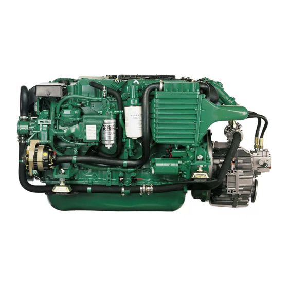
Presentation KAD/KAMD44P* and KAD/KAMD300* are in-line, direct injected 6-cylinder marine diesel engines, specially developed for planing boats. They are equipped with electronically controlled fuel injection, a mechanical supercharger, turbocharger, intercool- er, heat exchanger for thermostatically controlled fresh water cooling, electronically controlled engine speed con- trol and shifting. -
Page 14: What Is Edc
What is EDC EDC stands for Electronic Diesel Control. It is an electronic system for marine diesel engine control. The system has been developed by Volvo Penta and covers fuel control, diagnostic function and electronic engine speed control and shifting. -
Page 15: Orientation
Presentation Orientation KAMD44P/KAMD300, HS63 1. Electrical box 2. Oil filler cap, engine 3. EDC control module 4. Oil filter, engine 5. Charge air cooler 6. Dipstick, reverse gear 7. Starter motor 8. Fuel feed pump 9. Fuel filter 10. Injection pump 11. - Page 16 Presentation KAD44P/Professional, DP-E 1. Seawater filter 2. Electrical box 3. Oil filler cap, engine 4. EDC control module 5. Oil filter, engine 6. Charge air cooler 7. Starter motor 8. Fuel feed pump 9. Fuel filter 10. Injection pump 11. Generator 12.
- Page 17 Presentation KAD44P/DPX-A 1. Seawater filter 2. Electrical box 3. Oil filler cap, engine 4. EDC control module 5. Oil filter, engine 6. Charge air cooler 7. Starter motor 8. Fuel feed pump 9. Fuel filter 10. Injection pump 11. Generator 12.
- Page 18 Presentation KAD300/DP-G 1. Seawater filter 2. Electrical box 3. Oil filler cap, engine 4. EDC control module 5. Oil filter, engine 6. Charge air cooler 7. Starter motor 8. Fuel feed pump 9. Fuel filter 10. Injection pump 11. Generator 12.
-
Page 19: Instrumentation
Instrumentation This section contains descriptions of the instrument panels and panels available from Volvo Penta for your en- gine, with the exception of the Power Trim instrument, which is described in the section Power Trim. Note that the tachometer, oil pressure gauge, temperature gauge, charge indicator, ignition switch etc. which are shown here in- stalled in the instrument panels can be installed in other positions on some boats. -
Page 20: Control Panels
Instrumentation Control panels Control panels for the main control position and auxil- iary control position. 1. Siren for acoustic alarm that sounds if one of the warning lamps comes on. 2. Press button for instrument illumination. 3. Press button for testing and acknowledging alarms (see “Warning displays”... -
Page 21: Starting Switch
Instrumentation Starting switch Delivered with the starter keys is a plate containing the key code required when ordering additional starter keys. Do not keep the code where unauthorized per- sons can access it. S = Stop position. 0 = Key can be inserted and removed. I = Voltage on (drive position). -
Page 22: Control Panels (Edc)
Instrumentation Control panel EDC (type I) If the boat has a single engine there are three buttons in the control panel. If the boat has two engines there are six buttons in the control panel. Each button has an LED which indicates the present selection or status. Note that certain buttons and LEDs are duplicated on the control panel for two engines. - Page 23 Instrumentation Control panel EDC (type II) If the boat has a single engine there are three buttons in the control panel. If the boat has two engines there are six buttons in the control panel. Each button has an LED which indicates the present selection or status. Note that the neutral and diagnostic buttons are duplicated on the control panel for two engines.
-
Page 24: Controls
Controls This chapter describes the controls available from Volvo Penta. If your boat is equipped with controls which are not described here and you feel uncertain about the function please contact the dealer you purchased the boat from. Single lever control. Electronic... - Page 25 Controls Friction brake The control has a friction brake which can be adjusted as necessary to provide lighter or heavier lever action. Adjusting the friction brake: 1. Stop the engine. 2. Mover the control lever forwards so that the groove in the hub of the control lever is accessible.
-
Page 26: Power Trim
Power Trim Your Volvo Penta propulsion system is equipped with a Power Trim hydraulic trim system which makes it possi- ble to adjust the angle of the drive in relation to the stern of the boat. This adjusts the boat’s trim to obtain maxi- mum comfort and fuel economy in different operating conditions. - Page 27 Power Trim Lift range The lift range is used for lifting the drive to its maximum angle, however this cannot be used during normal op- eration of the boat. The range is used mainly for trailer transport of the boat. The Power Trim has an automatic stop which cuts off the current when the stop position is reached.
- Page 28 Power Trim Analogue trim instrument (DP) The trim instrument indicates the current trim position of the drive. The scale has five calibration points with the Beach and Lift range marked in red. 1. Trim range 2. Beach range (red). 3. Lift range (red) Trim instrument (DPX) The instrument shows the current position of the drive with- in the Trim range and the beginning of the Beach range.
-
Page 29: Starting The Engine
Starting the engine Make a habit of “visually” inspecting the engine and engine room before starting This will help you to quickly detect abnormalities that have occurred or are about to occur. Make sure instruments and warning displays indicate nor- mal values after starting the engine. -
Page 30: Starting Method
Starting the engine Starting method 1. Disengage the drive/gears Disengage the drive/gears by moving the control lever(s) to neutral at all control positions. 2. Switch on the power Turn the start key to position “I” to switch on the power. 3. - Page 31 Starting the engine Start using the start button Press the start button. Release the button immediately after the engine has started (note that when starting from the alternative control position, the starter key at the main control position must be turned to “I”). Overheating protection: If the starter motor is engaged for the maximum en- gagement time (30 seconds), the starter motor circuit is...
-
Page 32: Operation
Operation It is important to learn how to operate the engine, controls and other equipment safely and properly before setting off on a maiden voyage. Avoid violent and unexpected changes in course and gear engagement. There is a risk that someone aboard will fall over or overboard. WARNING! A rotating propeller can cause serious injury. -
Page 33: Diagnostic Information
Use a propeller with a greater pitch if the en- gine speed exceeds the wide open throttle range. Get in touch with your Volvo Penta dealer for advice. Overloading In all parachute towing, water skiing, etc. full throttle speed must not be less than 3600 rpm. -
Page 34: Synchronising Engine Speed
Operation Synchronising the engine speed When driving with twin engines, both the operating econo- my and comfort can be increased if the engines are operat- ing at the same engine speed (RPM). If the synchronisation function is activated, the engine speed (RPM) of the starboard engine is automatically ad- justed to that of the port engine if: 1. -
Page 35: Manoeuvering
Operation Maneuvering Only shift between forward and astern at engine idle speed as shifting at higher engine speeds can cause discomfort for those on board and unnecessary strain on the drive/re- verse gear or the engine to stop. Attempting to shift when the engine speed is too high will automatically result in the shift being delayed until the en- gine speed drops to approximately 1000 rpm. -
Page 36: Power Trim While Running
Operation Power Trim while running The Power Trim adjusts the drive angle to the stern of the boat to obtain maximum comfort and fuel economy at dif- ferent speeds, with varying loads, and in a range of wind and sea conditions. Power Trim settings and adjustment are controlled from the helm position using the controls and instruments described in the Power Trim section. - Page 37 Operation For maximum fuel economy Operate engine at a steady throttle opening. Trim the drive out/in slightly. The boat is most easily propelled and speed will increase in the position that gives the highest engine speed. The throttle opening can then be slightly reduced to retain the original speed.
- Page 38 If it is colored gray then water has entered the drive. If this is the case or if other damage has occurred to the drive it must be inspected at an authorized Volvo Penta workshop. If only the propeller has been damaged it must be replaced.
-
Page 39: Stopping The Engine
Stopping the engine The engine should be run for a few minutes at idle (in neutral) before turning it off. This will avoid boiling and even out the temperature. This is especially important if the engine has been operated at high engine speeds and loads. -
Page 40: Cold Weather Precautions
Stopping the engine Cold weather precautions To prevent freezing damage, the seawater system must be drained and the freshwater system coolant must have suffi- cient antifreeze protection. Refer to the cooling system sec- tion in chapter “Maintenance”. IMPORTANT! A poorly charged battery may burst as a result of freezing. -
Page 41: Maintenance Schedule
Maintenance schedule Your Volvo Penta engine and its equipment are designed for high reliability and long service life. They are built to withstand the marine environment, and to minimise their impact on it. Given regular maintenance, as in the schedule, these properties will be maintained and unnecessary malfunctions will be avoided. - Page 42 Maintenance schedule Every 200 hours / at least once a year, included in extended protection ● Air filter Change ................... page 44. ● Exhaust pipe. Inspection ................page 44. ● Supercharger. Checking of oil level .............. page 44. ● Drive belts. Checking of belt tension ............page 45. ●...
- Page 43 Maintenance schedule Every 1200 hours / at least every 5 years: ● Supercharger. Changing the oil ..............page 44. ● Heat exchanger. Inspection/Cleaning ............page 51. intercooler. Inspection/Cleaning ..............not shown Control cables and seals. Change ............. not shown Coolant pipes. Inspection ................not shown –...
-
Page 44: Maintenance
Maintenance This chapter describes how to carry out the above maintenance. Read the instructions carefully before starting work. Maintenance intervals are contained in the chapter above: Maintenance schedule WARNING! Read the safety precautions for maintenance and service in the chapter: Safety Information, before starting work. - Page 45 Maintenance: Engine, general Air Cleaner. Replacement Remove air cleaner cover. Remove the old air filter. Clean the air cleaner cover/housing as required. Take care that no contaminants enter the engine. Install the new air filter and air cleaner cover. Compressor. Checking oil Checking and topping up Unscrew and remove the dipstick.
- Page 46 Maintenance: Engine, general Drive belts. Checking and adjustment WARNING! Stop the engine before doing mainte- nance work. If the belts are tightened too hard, they can damage the water pump bearings, if they are too loose, they can slip. For this reason, check belt tension regularly. Proce- dure, please refer to the advice for each belt below.
- Page 47 Maintenance: Engine, general 3. Compressor belt Remove the protective cover. Undo the nut (1) enough so the belt slackens off. Tension the belt by tightening the domed nut (2) on the tensioner screw to 35–40 Nm. Use a torque wrench and a suitable socket. Lock the tensioner screw with the nut (1).
- Page 48 Maintenance: Engine, general Idling speed. Adjustment The engine idle speed is adjusted at the factory to 600 rpm. If required the idle speed can be adjusted within the range 600–700 rpm. Any adjustment must be made when the engine at operating temperature. NOTE! If the boat has a number of control positions, the adjustment can only be carried out from the main control position (normally the control position in the...
-
Page 49: Lubrication System
Lubrication system IMPORTANT! With a new or reconditioned engine, the oil and oil filters must be changed after 20–50 hours of operation. Use only the recommended grades of oil: See the chapter “Technical Data”. Oil change intervals can vary from 100 to 200 hours, depending on oil grade and sulphur content of the fuel. Note that oil change intervals must never exceed a period of 12 months. - Page 50 Maintenance: Lubrication system Oil level. Checking and topping up The oil level should be within the marked area on the dipstick (1) and should be checked every day the first time the engine is started. Topping up is done through the valve cover (2).
-
Page 51: Freshwater System
40% antifreeze in the system for complete protection against corrosion. Where there is no risk of damage from freezing the engine coolant can be fresh water with of Volvo Penta anti-corrosion fluid added. Mix according to the ins- tructionson the packaging. - Page 52 Maintenance: Freshwater system Coolant. Changing The corrosion-proofing additives become less effec- tive with time and the coolant must be changed. If the freshwater system is filled with antifreeze mixture it must be changed every other year. If the system is filled with anti-corrosion agent mixture it must be changed every year.
-
Page 53: Seawater System
Maintenance: Seawater system Seawater system The sea water system is the engine’s external cooling system. On engines with stern drives, the sea water pump sucks in water via the drive, after which the water passes the sea water filter before it is pumped through the inter- cooler, heat exchanger and the engine oil cooler. - Page 54 Maintenance: Seawater system Seawater system. Draining To prevent freezing damage the seawater system must be drained in cold weather where there is a risk of frost. WARNING! If the boat is left in the water, the seawater intake to the engine must be turned off with a seawater cock (non-standard equipment) or other method before draining the engine.
- Page 55 Maintenance: Seawater system Seawater system. Cleaning and inhibiting To prevent the build up of deposits and salt crystals in the seawater system it must be flushed with freshwa- ter. When the boat is laid up it must also be inhibited. WARNING! Risk of water penetration.
-
Page 56: Fuel Injection System
Maintenance: Fuel system Fuel system All work on the engine injection pump or injectors must be carried out at an authorized workshop. Use only the recommended grade of fuel: See the chapter “Technical Data”. WARNING! Fire risk. When carrying out work on the fuel system make sure the engine is cold. A fuel spill onto a hot surface or an electrical component can cause a fire. - Page 57 Maintenance: Fuel system Fuel filter. Replacement Clean the filter mounting. To avoid fuel spills put a plastic bag over the filter before it is unscrewed. Un- screw the filter. Moisten the filter rubber gasket with a little oil. Screw on the new filter by hand until it is in contact with the mating surface.
-
Page 58: Electrical System
Maintenance: Electrical system Electrical system The engine is equipped with a two-pole system electrical system which means that the voltage (minus) is returned directly from the starter motor minus terminal with the battery negative lead. Individual components on the system return voltage to the starter motor minus terminal via separate cables. - Page 59 Also check that all electrical connections are dry and free of oxidation and that there are no loose connec- tions. If necessary, spray these connections with a water-repellent spray (Volvo Penta Universal oil). Battery. Maintenance WARNING! Risk of fire and explosion. Never al- low an open flame or electric sparks near the battery or batteries.
- Page 60 Maintenance: Electrical system Battery. Charging WARNING! Danger of explosion! The batteries give off hydrogen gas during charging which when mixed with air can form an explosive gas – oxyhydrogen A short-circuit, naked flame or spark can cause a large explosion. Ensure that the ventilation is good.
- Page 61 Maintenance: Electrical system Electrical installations Leakage current from the electrical system can be caused by incorrect installation of electrical equip- ment. Leakage current can knock out the galvanic protection of components such as the drive, propeller, propeller shaft, rudder stock and keel and cause dam- age by electrolytic corrosion.
- Page 62 All equipment connected to the auxiliary battery should have separate switches. To simultaneously charge two independent battery circuits, fit a Volvo Penta charge distributor (ac- cessory) to the regular generator.
-
Page 63: Electrical Components Diagram
Maintenance: Electrical components diagram Electrial components diagram KAD44P, KAD300 12, 13 1. Starter motor 12. Injection pump 2. Generator 13. Stop solenoid 3. Starter relay 14. Engine speed (rpm) sensor 4. Main relay 15. Service socket 5. Stop relay 16. Needle lift sensor 6. - Page 64 Maintenance: Electrical components diagram KAMD44P, KAMD300 12, 13 1. Starter motor 12. Injection pump 2. Generator 13. Stop solenoid 3. Starter relay 14. Engine speed (rpm) sensor 4. Main relay 15. Service socket 5. Stop relay 16. Needle lift sensor 6.
-
Page 65: Reverse Gear
HS63VE is equipped with solenoid valves for electronically controlled shifting. IMPORTANT! Volvo Penta recommends the installation of a seawater filter to guarantee the proper coolant water flow to the engine and reverse gear. Contaminants in the seawater will otherwise foul the reverse gear radiator and other cooling system components. - Page 66 Maintenance: Reverse gear Propeller shaft seal If the boat has a Volvo Penta shaft the shaft seal must be vented and lubricated directly after launching. Vent the bushing by pressing it together while press- ing down on the shaft until water appears. Then press in approx.
-
Page 67: Drive
Maintenance: Drive Drive Your drive is protected against galvanic corrosion. This protection consists of five layers of paint, sacrificial an- odes and ground braids. The ground braids maintain a connection between the different components of the drive. A broken connection can result in the rapid corrosion of an individual component even though the protection is otherwise effective. - Page 68 Maintenance: Drive DP drive The sacrificial anodes can be found at the lower edge of the shield (1) and on the gear housing in front of the propellers (2). Undo the two screws holding the anode (1). Remove the anode and the support plate under the anode. Clean the mating surface.
- Page 69 Remove the plug on the gear housing and let the oil run out. If oil is discolored, contact an au- thorized Volvo Penta workshop. Reinstall plug and O ring. Always replace a damaged O ring with a new one.
- Page 70 Removal of the drive re- quires special knowledge and tools. If in doubt contact your Volvo Penta workshop for assistance. WARNING! Never work on the drive bellows or hydraulic system without locking the drive in its raised position so that it cannot fall down.
- Page 71 Maintenance: Drive DP: If the drive has been removed the steering rack and drive controlling the trim sensor may have come out of position. Turn the cog until the notched tooth is visible. Install the steering rack so that the first cog position meshes with the marked tooth.
-
Page 72: Steering
This leak must immediately be localized and remedied. Please contact your nearest authorized Volvo Penta work- shop for repairs. The steering system is filled with au- tomatic transmission fluid (ATF), the fluid should not normally require changing. - Page 73 Maintenance: Steering DPX Hydraulic pump Oil level Check with the engine(s) idling. The level should be between MAX and MIN markings on the dipstick. NOTE! The level is slightly higher with the engine stopped. Fill with ATF. For ATF grade, see Technical data.
- Page 74 Please contact your nearest authorized Volvo Penta workshop for as- sistance. DPX Parallel strut. Checking The parallel strut (twin and triple installation) is a vital safety component.
-
Page 75: Propellers
Installation Propellers. DPX-drive 1. Grease both the propeller hubs. Use Volvo Penta NOTE! A tool for installing and removing the propel- grease (water resistant). lers (please refer to the illustration) is provided with the drive. - Page 76 Maintenance: Propellers Propellers. DP-drive Installation NOTE! A tool for installing and removing the propel- 1. Apply some Volvo Penta water resistant grease to lers (please refer to the illustration) is provided with the propeller hubs. the drive. 2. Switch the ignition on and put the control lever in the forwards position.
-
Page 77: Laying Up/Launching
Laying up/Launching Before taking the boat out of the water for winter/out-of-season storage have an authorized Volvo Penta workshop inspect the engine and other equipment. Have any necessary repairs or service work carried out so that your boat is in top condition for the new season. -
Page 78: Bringing Out Of Winter Storage
Laying up/Launching Bringing out of storage ● Check oil level in the engine and drive/reverse ● Paint the drive and hull: See next page. gear. Top up if necessary. If there is inhibiting oil in the system drain and fill with new oil, change oil ●... -
Page 79: Painting The Drive And Underwater Hull
Wash off using thinners or similar. Any pores in the surface should be filled and sanded down. Paint using Volvo Penta original primer and topcoat. Let the paint dry. A further two coats of Volvo Penta anti-fouling primer should then be ap- plied. -
Page 80: Fault-Tracing
A number of symptoms and possible causes for engine disturbances are described in the table below. If faults or hitches arise that you cannot solve alone, you must always get in touch with your Volvo Penta dealer. WARNING! Read the safety directions for maintenance and service in the chapter “Safety information” before starting work. -
Page 81: Starting Using Auxiliary Batteries
Fault-tracing Start using auxiliary batteries WARNING! Ventilate well. Batteries generate ox- yhydrogen gas, which is extremely flammable and explosive. A short circuit, naked flame or spark can cause a powerful explosion. Never reverse the polarity of the battery. Risk of sparks and explosion. -
Page 82: Emergency Shifting
Fault-tracing Emergency shifting If a fault occurs which prevents the drive or reversing gear from being operated (shifted) with the control le- ver, it is possible to shift manually, using the descrip- tion below. Note. The descriptions refer to electrically shifted drives and reversing gear. -
Page 83: Calibrating The Control Unit
Fault-tracing Calibrating the control If a control is replaced, the new control must be cali- brated. During calibration, a number of predetermined control lever positions for the EDC system are defined. Preparations Before the control is calibrated the EDC system must be put into calibration mode as follows: 1. - Page 84 Fault-tracing Calibration. Electronic single lever control NOTE! When calibrating the control for two engines, both the control levers must be calibrated at the same time so that the lever positions are the same for both engines. 1. Put the EDC system in calibration mode according to the instructions in “Preparations”.
- Page 85 Fault-tracing Calibration. Mechanical single lever control NOTE! When calibrating the control for two engines, both the control levers must be calibrated at the same time so that the lever positions are the same for both engines. Some controls from third party manufacturers have a greater throw (A) at wide open throttle (WOT) with re- verse gear disengaged than at WOT with the reverse gear engaged.
- Page 86 Fault-tracing NOTE! When calibrating the control for two engines, both the control levers must be calibrated at the same time so that the lever positions are the same for both engines. 1. Put the EDC system in calibration mode according to the instructions in “Preparations”.
-
Page 87: Diagnostic Function
Diagnostic function Diagnostic function The diagnostic function monitors and checks that the EDC system is functioning correctly (including the boost pressure and engine coolant temperature (ECT)). The diagnostic function has the following tasks: ● To detect and locate malfunctions ● To inform that malfunctions have been detected ●... -
Page 88: Reading Off Diagnostic Trouble Codes (Dtcs)
Diagnostic function If the diagnostic button indicator flashes 1. Reduce the engine speed to idle. 2. Press the diagnostic button to acknowledge the message. 3. Release the diagnostic button and make a not of the diagnostic trouble code (DTC) that is flashed out. -
Page 89: Erasing Diagnostic Trouble Codes (Dtcs)
Diagnostic function Erasing diagnostic trouble codes (DTCs) The DTC memory for the diagnostic function is reset each time the power to the engine is interrupted. NOTE! The power must be shut-off completely. Stop the engine and check that the start key(s) are in posi- tion 0 at all control positions. -
Page 90: Diagnostic Trouble Codes (Dtcs)
Diagnostic function Diagnostic trouble codes (DTCs) WARNING! Read the safety precautions for maintenance and service in the chapter “Safety Information” before starting work. Code 1.1 No fault Code 1.6 Calibration There are no diagnostic trouble codes (DTCs) stored and Cause: The control on the main control position (usually no malfunctions have been registered. - Page 91 Diagnostic function Code 2.4 Engine speed (RPM) sensor Code 2.7 Potentiometer Cause: The engine speed (RPM) sensor transmits no Cause: The control module receives no information from signal to the control module at start. the potentiometer in the control (applies to the potentiom- eter for the engine speed lever in dual lever controls).
- Page 92 Diagnostic function Code 5.4 Forward gear Code 3.4 Gearshift control actuator Cause: Short-circuit or open-circuit in the wiring for re- Cause: The control module receives no position signal verse gear/gearshift control actuator (drive) for the forward from the gearshift control actuator (drive) or the signal is gear.
- Page 93 Diagnostic function Code 5.6 Boost pressure Code 8.3 Calibration Cause: High boost pressure. Cause: The calibration values cannot be stored by the control module. Consequence: The engine power is reduced until normal values are obtained. Consequence: The control must be calibrated before each start.
-
Page 94: Technical Data
Technical Data Engine General information Engine designation KAD44P-C, KAD44 Professional, KAMD44P-C, KAD300-A, KAMD300-A Idling speed..........590-610 rpm. Swept volume ..........3.59 liter (3.8 US quart) Injection sequence ........1-5-3-6-2-4 Direction of rotation (seen from front) .... Clockwise Max. forwards inclination ....... 4°... -
Page 95: Fuel Specification
Technical Data Supercharger Oil volume ............ 0.1 liter (0.2 US pint) Oil grade ............Volvo Penta, part no. 1141641-9 Cooling system Thermostats open/fully open ......81°C/94°C Fresh water system volume, app ....19 liter (20 US quart) Electrical system System voltage .......... -
Page 96: Power Trim
ATF (Dexron II) VP hydraulic steering (optional DP/HS63) Oil grade ............Volvo Penta part no. 1141640-1 , Shell Aero 4, Texaco HO15 Esso Univis N15, Chevron Aviation Fluid A, Mobil Aero HFA VP Xact hydraulic steering (DPX) Oil grade ............ - Page 97 Notes ..............................................................................................................................................................................................................................................................................................................................................................................................................................................................................................................................................................................................................................................................................................................................................................................................................................................................................................................................................................................................................
- Page 98 Notes ..............................................................................................................................................................................................................................................................................................................................................................................................................................................................................................................................................................................................................................................................................................................................................................................................................................................................................................................................................................................................................
- Page 99 ✂ Yes please, I would like an operator’s manual in English at no charge. Publication number: 7742203-8 Post or fax this coupon to: Document & Distribution Center Name Order Department ARU2, Dept. 64620 Address SE-405 08 Göteborg Sweden Fax: +46 31 545 772 Orders can also be placed via the Internet: http://www.volvopenta.com/...
- Page 100 ✂ Sí gracias, deseo recibir gratuitamente un libro de instrucciones en español. Número de publicación: 7742206-1 Franquear o enviar fax a: Document & Distribution Center Nombre Order Department ARU2, Dept. 64620 Dirección SE-405 08 Göteborg Suecia Fax: +46 31 545 772 El pedido puede hacerse tam- bién por internet: http://www.volvopenta.com/...
- Page 101 ✂ Ja graag, Ik wil kosteloos een instructieboek in het Nederlands ontvangen. Publicatienummer: 7742213-7 Stuur of fax de coupon naar: Document & Distribution Center Naam Order Department ARU2, Dept. 64620 Adres SE-405 08 Göteborg Zweden Fax: +46 31 545 772 U kunt ook bestellen via internet: http://www.volvopenta.com/...
- Page 102 ✂ Sim, obrigado(a)! Gostaria de receber gratuitamente um manual de instruções em português. Número de publicação: 7742214-5 Envie o talão pelo correio ou um fax para: Nome Document & Distribution Center Order Department Endereço ARU2, Dept. 64620 SE-405 08 Göteborg Sweden Fax: +46 31 545 772 A encomenda também pode...
Need help?
Do you have a question about the KAD/KAMD44P and is the answer not in the manual?
Questions and answers