Table of Contents

Related Manuals for BUSCH Huckepack HO 0429 F


Summary of Contents for BUSCH Huckepack HO 0429 F
- Page 1 Installation and Operating Instructions Rotary Vane Vacuum Pumps Huckepack HO 0429-0441 F ATEX Version Ateliers Busch S.A. Zone industrielle 2906 Chevenez Switzerland 0870536238/ E0002/ 181212 / Original instructions / Modifications reserved...
-
Page 2: Table Of Contents
Mounting position and space ....8 Busch – All over the World in Industry ....40 Inlet connection . -
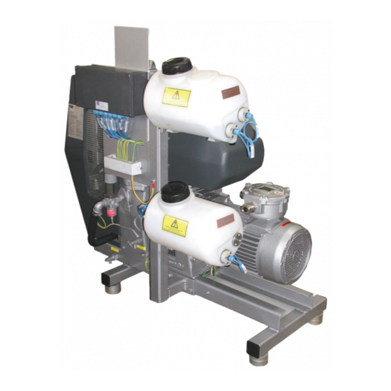
Page 3: Safety Guards
Safety guards 1 Cover seal fluid pump 2 Cover motor fan 3 Coupling safety grill 4 Cover V-belt drive 5 Radiator safety grill 6 V-belt drive safety grill 1 Seal fluid tank 2 Flushing fluid vessel (option) 3 Holding plate 4 Bypass valve 5 Flap valve 6 Exhaust silencer (accessory) -
Page 4: Product Description
After processing, it may be that the vacuum pump must be kept running Before using the vacuum pump with aggressive or toxic gases, please for a time or that it must be flushed. In case of doubt, please contact contact imperatively your local Busch Agency. your local Busch-Agency. WARNING... -
Page 5: Radiator Cooling
(boiling point, partial vapor pressure). In case of acids or alkaline vapors the cooling water net. Water circulation is made by an integrated cooling respectively solvents, consult yout local Busch agency. watercirculating pump. The cooling water is firstly pumped through the pump housing where it takes the heat from the compression process. -
Page 6: Cooling
Liquid and solid particles must not enter the pump, refer to the heat from the compression process. Finally, the cooling water is cooled running limits. Consult your local Busch Agency. with a ribbed radiator. Thanks to an axial fan, the ribbed radiator conducts the heat into the environment. -
Page 7: On/ Off Switch
If you have any doubts, When transporting the vacuum pump with a fork truck, take care of contact your Busch representative. the thrust point. This may vary according to the accessories that have been assembled. -
Page 8: Storage
Preservation CAUTION If the vacuum pump will be exposed to unfavourable ambient conditions (for example, aggressive environment, frequent temperature changes), Do not work, walk or stand under suspended loads. begin immediately with preservation work on the vacuum pump. CAUTION In case of favourable ambient conditions, perform preservation work on the vacuum pump if a storage period of more than three months is Please check out the weight of the vacuum pump before lifting it up planned. -
Page 9: Inlet Connection
If necessary, attach safeguards. cuum pump. If you have any doubts, contact your Busch representative. l Make sure that the oil sight glasses are easily accessible... -
Page 10: Electrical Connection/ Checks
In case of long discharge lines, the line cross-section should be larger than the discharge flange to prevent a drop in the performance of the vacuum pump. If you have any doubts, contact your Busch representa- tive. Electrical connection/ Checks... -
Page 11: Drive
Drive Functional diagram HO 0429-0441 F with radiator cooling Installation and start-up HO 0429-0441 F Page 11 0870536238 (En) - Page 12 Functional diagram HO 0429-0441 F with direct cooling 0206 1 Dust separator 2 Shut o tap 3 Temperature regulating valve Installation and start-up HO 0429-0441 F Page 12 0870536238 (En)
-
Page 13: Legend Of Functional Diagram
For the resistance thermometers and the pressure sensor, the following Legend of functional diagram alarm values, i. e. switch-off values, should be adjusted: Designation Description Function Adjustment values (Level HO 0429 F HO 0433 F HO 0437 F HO 0441 F TSA+/0101 Resistance thermo- Warning and alarm in case of too... - Page 14 As an option, an alarm can be set up, see following figures. The speed controller is factory adjusted to the nominal speed. If this value is lower or higher of 100 rpm (n ), an alarm releases. The drive apparatus of the speed controller is wholly configurated in the factory.
-
Page 15: Working Drive Procedure
Working drive procedure Installation and start-up HO 0429-0441 F Page 15 0870536238 (En) -
Page 16: Installation
Star connection (High voltage) Installation Mounting l Make sure that the “Necessary installation instructions” are follo- wed. l Fasten or install the vacuum pump at its final installation site. Connecting electrically WARNING Risk of electrocution, risk of damage. Electrical installation must be performed by a suitably qualified elec- CAUTION trician who knows and follows the following regulations: - IEC 364 or CENELEC HD 384 or DIN VDE 0100,... - Page 17 Designation Description Explosion protection TSA+/0101 Resistance thermometer (PT100) Ex ia 11mW TSA+/0102 Resistance thermometer (PT100) Ex ia 11mW TSA+/0103 Resistance thermometer (PT100) Ex ia 11mW TSA+/0104 Safety thermostat Ex ib II C T6 (break contact) TSA+/0105 Safety thermostat Ex ib II C T6 (break contact) LSA-/0201 Level switch...
-
Page 18: Measuring Transmitter For The Resistance Thermometer (Option)
Measuring transmitter for the resistance Incorrect or Sensor is incorrectly Reinstall sensor correctly thermometer (option) inaccurate installed measured value Heat dissipation via Monitor sensor Assembly In connecting head sensor installation positioning Manufacturer Endress + Hauser Sensor connection Monitor sensor (2 wire) connection Type TMT 187 BFI... -
Page 19: First Filling With Cooling Water
The Huckepack vacuum pumps are lubricated. Besides oil other seal l Connect the hose at the water outlet fluids are possible. Please contact your local Busch representative or re- Circuit cooling with thermostat for water circulation quest our leaflet “Special Seal Fluids for Vacuum Pumps”. -
Page 20: Adjustment Of The Seal Fluid Pump
Different adjustment of the oil pump can be done depending on custo- When using toxic, inflammable and/ or explosive gases, make sure mer process conditions after validation by Busch. that the system corresponds in design to applicable local and natio- Adjustment of the seal fluid pump nal safety regulations and that all applicable measures are followed. -
Page 21: Maintenance
- Seal fluid DIN 51506, lubricant group VC 150 (compressor oil minated with foreign materials that are dangerous to health, the oil Busch VM150). and condensates will also be contaminated. - Seal fluid VG68 - VG150 according to ISO3448, flash point >210°C according to ISO2592, authorization according to US FDA... -
Page 22: Assembly
Type of grease: high melting-point grease up to 150°C. Consistence: Rapid exchange of stage SKF LGHP-2/1lithium grease NOTE: Huckepack vacuum pumps are constructed in a way that the ex- change of the HP stage can be done easily. The different steps (circuit cooling) are as follows: l Switch off the pump l Drain off the cooling water l Take off the V-belt hood... -
Page 23: Maintenance Of Add-On Pieces
Seal fluid separator Pump type Dimension "A" Æ Shaft The seal fluid level on the sight glass of the collecting vessel must be checked daily. If the seal fluid level has reached the sight glass, draw off HO 0429 F 38 mm 26 mm the used seal fluid through the drain plug. -
Page 24: Suction Filter
The flushing liquids depend on the process. Oils, synthetic oils, oil/ diesel or oil/ petroleum mixtures can be used. In case of doubt, please contact l Clean the PTFE-filter cartridges with solvent your local Busch-Agency. Inspection and adjustment of the belts CAUTION SEPARATION ZONE... -
Page 25: Maintenance Program
Control or exchange the vanes Every 16 000 hours of operation, at the latest after 4 years l A main inspection of the vacuum pump (Busch) l Replace the V-belt Every 20 000 hours of operation (for HO 0433/... -
Page 26: Checking The Colour Of The Seal Fluid
Make sure that the seal of the drain plug is not damaged and that it Busch service will only accept vacuum pumps that come with a comple- sit properly. Replace if necessary. tely filled in and legally binding signed form. -
Page 27: Dismantling And Disposal
Dismantling and disposal DANGER If the vacuum pump has pumped gases that were contaminated with foreign bodies that are hazardous to health, the seal fluid and condensate are also contaminated with these foreign bodies. These foreign bodies can penetrate into pores, openings and other internal parts of the vacuum pump. -
Page 28: Exploded Drawing
Exploded drawing Exploded drawing HO 0429-0441 F Page 28 0870536238 (En) -
Page 29: Wearing Parts
Wearing parts 0512 500 423 Rubber coupling insert 0512 000 114 Coupling star 0512 000 001 Coupler sleeve Overhaul kit HO 0429 F N° 0993 543 974 0513 534 744 V-belt Part N°. Part Qty. Pos. 0541 000 029 Non-return valve 0437 000 080 Taper pin 69/ 169... - Page 30 0472 510 848 Sleeve 54/ 154 0481 000 257 Flat gasket 0433 511 321 Tolerance washer 56/ 156 0481 000 272 Float switch seal 0433 511 322 Tolerance washer 55/ 155 0482 000 079 Level switch seal 0433 511 323 Tolerance washer 57/ 157 0482 000 096...
-
Page 31: Troubleshooting
Disassemble or reassemble the exhaust valve (Busch service). in partially open position. A vane is blocked in the rotor or otherwise dama- Free the vanes or replace with new ones (Busch service). ged. The radial clearance between the rotor and the cy- Readjust the vacuum pump (Busch service). - Page 32 Remove the drive motor and check the drive motor and the vacuum pump separately. If the vacuum pump is blocked: Repair the vacuum pump (Busch service). The drive motor is defective. Replace the drive motor (Busch service). The vacuum pump is blocked Solid foreign matter has entered the vacuum Repair the vacuum pump (Busch service).
- Page 33 The vacuum pumps runs very Defective bearings. Repair the vacuum pump (Busch service). noisily Worn coupling element. Replace the coupling element. Stucked vanes. Use only approved oils (see “Oil”) and change more fre- quently. The vacuum pump runs very hot Insufficient air ventilation.
-
Page 34: Seal Fluid Type/ Quantity
Seal fluid type/ quantity Seal fluid type l Make sure that the oil type corresponds to specification: The type of seal fluid depends on the working area. Seal fluids adequate to DIN 51506, lubricant group VC 150 must be used. –... -
Page 35: Technical Data
Technical data Technical data HO 0429 F HO 0441 F HO 0433 F HO 0437 F Nominal suction capacity 50 Hz Ultimate pressure hPa (mbar) Nominal motor rating 50 Hz Motor nominal motor speed 1000 1000 1000 1000 50 Hz LP (low pressure) stage 2150 2150... -
Page 36: Eu-Declaration Of Conformity
EU-Declaration of Conformity This Declaration of Conformity and the CE-mark affixed to the nameplate are valid for the machine within the Busch scope of delivery. This declara- tion of Conformity is issued under the sole responsibility of the manufacturer. When this machine is integrated into a superordinate machinery the manufacturer of the superordinate machinery (this can be the operating company, too) must conduct the conformity assessment process for the superordinate machine or plant, issue the Declaration of Conformity for it and affix the CE-mark. - Page 37 Note...
- Page 38 Note...
- Page 39 Note...
-
Page 40: Busch - All Over The World In Industry
Busch – All over the World in Industry www.buschvacuum.com Finland Malaysia Spain Argentina Busch Malaysia Sdn Bhd. Busch Vakuumteknik Oy Busch Argentina S.R.L. Busch Ibérica S.A. 4&6, Jalan Taboh 33/22, Seksyen 33 Sinikellontie 4 Santo Domingo 3076 Pol. Ind. Coll de la Manya...
Need help?
Do you have a question about the Huckepack HO 0429 F and is the answer not in the manual?
Questions and answers