Table of Contents
Advertisement
Quick Links
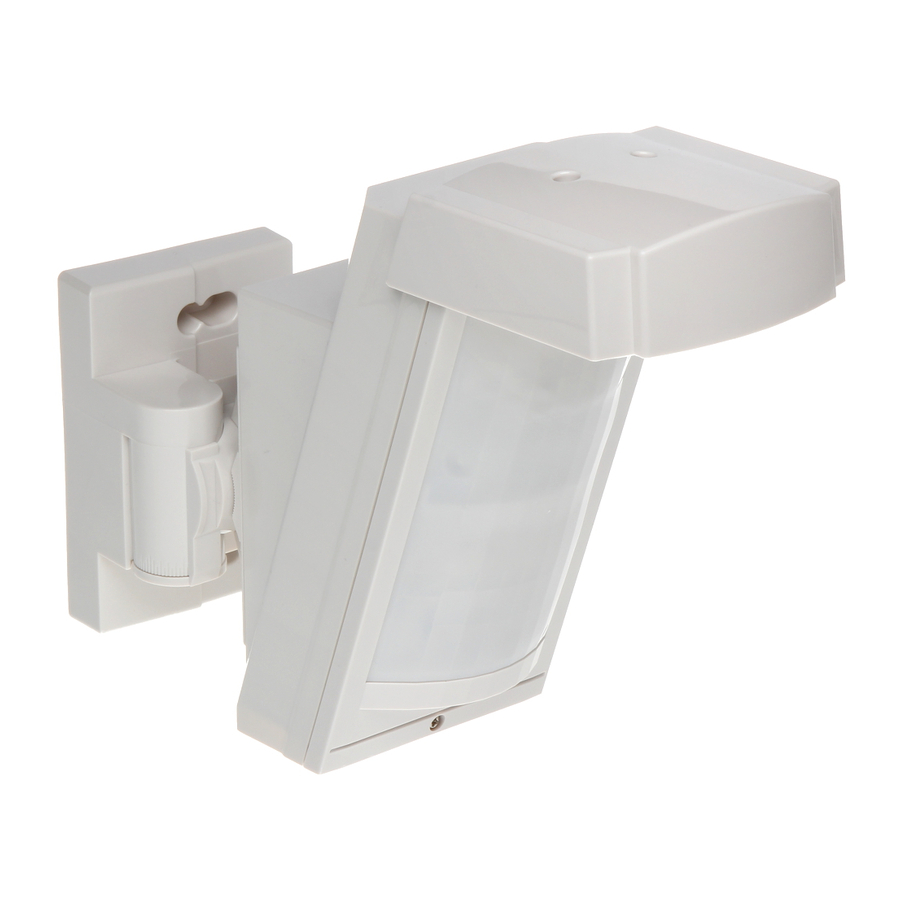
The JA-158P wireless outdoor PIR detector
The JA-158P is an outdoor intruder wireless detector designed to detect
human body movement in a protected area. It supplements a double-zone
PIR sensor HX-40RAM produced by Optex with a Jablotron transmitter
JA-150TX-V4 enabling the detector to be used within the JABLOTRON 100
system. The optical part of the detector has 2 PIR sensors with non-
overlapping 94 zone detection, a high immunity to false alarms and
the detection of small animals. The detector includes an Antimasking
function – protection against covering the view and it also has two tampers
(front and back) built-in. They immediately report opening the detector
or attempting tampering. The detector does a self-test periodically and sends
its status to the control panel. The detector should be installed by a trained
technician with a valid certificate issued by an authorised distributor.
Installation
Choose a proper place for detector installation according to the following:
The detector must be installed in a position where its bottom surface
is parallel to the watched zone (either directly on the wall, or possibly,
if a change of direction is required, the supplied joint can be used).
This condition is essential for good immunity to false alarms.
For more information see Figure 1.
The detector should be installed 2.5 – 3 m above the ground.
No other moving objects (bushes, trees, high grass, etc.) should be
situated in the detection area of the detector. These objects can be
masked out using the supplied foils. Avoid direct action by strong
sources of light (sun reflections). You can use the supplied viewing
hood for this purpose.
When selecting the right place to install your detector, keep in mind that
the best movement detection is provided when the detection zones
intersect Figure 2.
Figure 1
Figure 2
Procedure:
1.
Unfasten the securing screw on the bottom side of the upper cover and
remove it.
2.
Pull the plastic tab under the lower PIR sensor slightly to remove the
optical part. Warning: Do not touch the detector sensing face
during handling.
3.
Use a screwdriver to punch a hole on the right of the bottom detector
cover in order to pull the rear TAMPER cable through (supplied
in the package).
When installed without the joint holder:
Use the Base Mounting Template from the box lid.
Figure 3 detector configuration
The JA-158P wireless outdoor PIR detector
Pull the rear TAMPER cable through the punched hole in the bottom
detector cover and fix a magnetic contact to the place according
to the template (Base side).
Mark a place on the wall where you want to install the detector
– i.e. holes for the screws and the magnet (Wall side), and fix
the magnet to the wall.
Fix the rear cover on the wall while checking the position of the magnet
and the reed contact (they should be as close as possible).
When installed with the joint holder:
Use the Bracket Base Mounting Template from the box lid.
Press the plastic tab to remove the screw cover (secured with
a plastic cord against falling during work).
Unscrew the securing screw (inside under the cover) to loosen the joint
and swivel it to one side to gain access to the installation holes.
Pull the rear TAMPER cable through the cavity in the joint and fix
the magnetic contact in the given place (between plastic lugs).
Mark a place on the wall where you want to install the detector
– i.e. holes for the screws and the magnet (Wall side), and fix
the magnet to the wall.
Fix the joint holder to the wall while checking the position of the magnet
and the reed contact (they must touch).
Now screw the bottom cover together with the joint holder. Remove
the central screw which blocks vertical movement and screw it through
a hole in the bottom cover.
Pull the rear TAMPER cable through the opening you have punched
in the bottom detector cover and insert the rear TAMPER connector into
the pins marked EXT.TMP (3) see Figure 4 (remove the jumper
installed in production).
Enrolling the detector to the system
The signal transmitter for wireless communication is located underneath
the optical part of the detector. The batteries are inserted into the battery
holder of the OPTEX motion detector. Use two CR123A (3 V, 1500 mAh)
lithium batteries from the same manufacturer. If an increased lifetime
is needed, you can also use a third battery. The correct position
of the batteries is indicated on the battery holder. Alternatively, LS(T) 14500
(3.6V, AA) lithium batteries can be used. When inserting the batteries, it is
necessary to remove the part of the holder held in place with a metal clip.
Enrollment procedure to the system:
a.
There must be a JA-11xR radio module installed in the control
panel.
b.
Go to the F-link software, select required position in the Devices
window and launch the enrollment mode by clicking on the Enroll
option.
c.
Insert the batteries (mind the correct polarity). When the first
battery has been inserted into the battery holder an enrollment
signal is transmitted to the control panel and the detector
is enrolled to the selected position.
Figure 4 – Transmitter JA-150TX-V4: 1 – terminals, 2 – option DIP switch,
3 – external tamper connector, 4 – external antenna jumper, 5 – external
antenna connector
If needed the transmitter can be equipped with an AN-868 (2PIN)
external antenna connected to the connector (5) and disconnect
the jumper (4).
266
148
Figure 5: Detector dimensions
1 / 2
N.C.
N.O.
State (INP)
Pulse (INP)
AUX = Fault
AUX = antimasking
Not used
Factory settings highlighted by bold letters.
99
MMY51504
Advertisement
Table of Contents

Subscribe to Our Youtube Channel
Related Manuals for jablotron JA-158P


Summary of Contents for jablotron JA-158P
- Page 1 The JA-158P wireless outdoor PIR detector The JA-158P is an outdoor intruder wireless detector designed to detect Pull the rear TAMPER cable through the punched hole in the bottom human body movement in a protected area. It supplements a double-zone...
- Page 2 ERC REC 70-03 Area coverage test (DIP1) – the energy saving mode is not applied JABLOTRON ALARMS a.s. hereby declares that the JA-158P is in a and each detectable movement is indicated by an LED. The alarm is always compliance with the relevant Union harmonisation legislation: transmitted regardless of the energy saving mode settings (DIP2).
Need help?
Do you have a question about the JA-158P and is the answer not in the manual?
Questions and answers