Advertisement
Quick Links
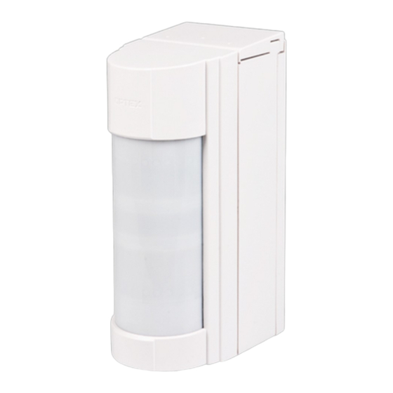
The JA-159P wireless outdoor PIR detector
The JA-159P wireless outdoor intruder detector is designed to detect
human body movement in a protected area. It supplements a double-
zone PIR sensor produced by Optex with a Jablotron transmitter
enabling the detector to be used within the JABLOTRON 100 system.
The optical part of the detector has 2 PIR sensors and high immunity to
false alarms and the detection of small animals. The detector includes an
Anti-masking function – protection against covering the view and it also
has two tampers (front and back) built in. They immediately report
opening the detector or attempting tampering. The detector does a self-
test periodically and sends its status to the control panel. The detector
should be installed by a trained technician with a valid certificate issued
by an authorised distributor.
Installation
Choose a proper place for detector installation according to the
following:
1.
The detector has to be installed onto a vertical wall (in a position
where its bottom surface is parallel to the watched zone).
2.
The detector should be installed 0.8 – 1.2 m above the ground.
3.
The best movement detection is provided when the detection beams
intersect.
4.
No other moving objects (bushes, trees, high grass, air-conditioners,
etc.) should be situated in the field of sight of the detector. Avoid
direct action by strong sources of light (sun reflections, etc.).
Note: If multiple JA-159P detectors are used, they mustn´t be
installed face to face with each other and its recommended to install
them with a minimum 1 m distance.
Procedure:
1. Unscrew the locking screw placed on bottom of the upper cover
of the detector (1) and remove the detection part cover (1).
2. Unscrew the 2 screws which hold the detector´s main board (2)
and pull it out by tilting as you pull it out.
3. Remove the battery holder.
4. Remove the rear box cap (5).
5. Unscrew the 2 screws which link the rear cover (3) with the
mounting plate (4).
6. The detector can be mounted onto a level mounting place by the
2 screws through the mounting plate (4). Or it can be mounted
on pole by ties.
7. Put the detectors parts back together in the opposite order when
it´s finally fixed to the mounting place (4).
Warning: Do not touch the detector sensing face during handling.
2
1
Fig. 1.: 1 – front cover, 2 – detector main board, 3 – rear cover,
4 – mounting plate, 5 – rear cover cap
Fig. 2.: Detector installation. Standard wall installation and fixing by ties.
The JA-159P wireless outdoor PIR detector
5
4
3
1 / 2
Enrolling the detector to the system
The signal transmitter for wireless communication is located under
the main board part of the detector. The batteries are inserted into the
battery holder of the OPTEX motion detector. Use two CR123A (3 V,
1500 mAh) lithium batteries from the same manufacturer and
replace both batteries at the same time. If an increased lifetime is
needed, you can also use a third battery. The correct position of the
batteries is indicated on the battery holder. Alternatively, LS(T) 14500
(3.6V, AA) lithium batteries can be used. When inserting the batteries, it is
necessary to remove the part of the holder held in place with a metal clip.
Enrollment procedure to the system:
a. There must be a JA-110R radio module installed in the
control panel.
b. Go to the F-Link software, select the required position in the
Devices window and launch the enrollment mode by clicking on
the Enroll option.
c. Insert the batteries (mind the correct polarity). When the first
battery has been inserted into the battery holder an enrollment
signal is transmitted to the control panel and the detector is
enrolled to the selected position. Assemble the detector.
Status (INP)
AUX = Fault
Not used
Factory settings highlighted by bold letters.
Fig. 3 - Transmitter: 1 – terminals, 2 – option DIP switch (pre-set from
factory, 3 – external tamper connector, 4 – external antenna jumper,
5 – external antenna connector
If needed the transmitter can be equipped with an AN-80 or AN-81
external antenna connected to the connector (5) and disconnect the
jumper (4).
Setting up the optical part of the
detector
The optical part of the detector includes 2 PIR sensors with AND
logic. They detect movement in two planes. The detecting angle of
the lower PIR sensor can be adjusted. The alarm signal is triggered if
only both detecting planes are triggered at the same time. By shifting
the lens set up the tilt of the lower detecting plane according to the
following picture and table.
Fig. 4.
The following table represents the values included in the figure:
Maximum range of the lower detecting
Position
Average value
1
12 m
2
8.5 m
3
6 m
4
3.5 m
5
2.5 m
Table
1.
Warning: The maximum detection length of the lower detection plane
may vary as above due to environmental thermal conditions. This must be
taken into consideration during detection range adjustment.
N.C.
N.O.
Pulse (INP)
AUX = Antimasking
part
see following limits:
10 to 17 m
7 to 12 m
5 to 8.5 m
3 to 6 m
2 to 3.5 m
MMY51801
Advertisement

Related Manuals for jablotron JA-159P


Summary of Contents for jablotron JA-159P
- Page 1 The JA-159P wireless outdoor PIR detector The JA-159P wireless outdoor intruder detector is designed to detect Enrolling the detector to the system human body movement in a protected area. It supplements a double- The signal transmitter for wireless communication is located under zone PIR sensor produced by Optex with a Jablotron transmitter the main board part of the detector.
- Page 2 Before battery replacement the control panel has to be switched to service mode (see installation manual of the control panel) and JABLOTRON ALARMS a.s. hereby declares that the JA-159P is then it is possible to open the cover of the detector. Always use...
Need help?
Do you have a question about the JA-159P and is the answer not in the manual?
Questions and answers