Advertisement
Quick Links
JABLOTRON
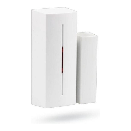
JA-83M
CZ B
ezdrátový magnetický detektor otev ení
EN
Wireless magnetic door detector
DE
Funk - Öffnungsmelder
SK B
ezdrôtový magnetický detektor otvorenia
fig. 1
2
+
1
3
fig. 3
CZ
1. montážžní otvory pro upevn ní vysíla e; 2. montážžní otvory
pro upevn ní magnetu A, 3. pozice magnetu A,B; 4. sériové íslo;
5. jazý kový kontakt; 6. baterie CR123A; 7. sabotážžní sníma ;
8. nastavení reakce
EN
1. mounting holes of the detector; 2. mounting holes of the
magnet A, 3. magnet A and B position marks; 4. serial number;
5. reed contact; 6. battery CR123A; 7. tamper; 8. settings jumper
DE
1. Montage Öffnungen für das Befestigen des Senders;
2. Montage Öffnungen für die Befestigung des Magnets A, 3.
Position
des
Magnets
A,B; 4. Seriennummer;
5. Schutzrohrkontakt; 6. Batterie CR123A; 7. Sabotage Sensor;
8. Einstellen der Reaktion
SK
1. montážžne otvory pre upevnenie detektora; 2. montážžne
otvory
pre
upevnenie
magnetu
A,
3.
A,B; 4. sériové
íslo; 5. jazý kový kontakt; 6. batéria CR123A;
7. sabotážžny (Tamper) kontakt; 8. nastavenie reakcie
1.
2.
A,B; 4.
; 5.
CR123A; 7.
; 8.
A A
40 / 40
fig. 5
B
fig. 6
JA-83M CZ / EN / DE / SK / RU
MLL51000-print.indd 1
MLL51000-print.indd 1
Detektor JA-83M je komponentem systému OASiS firmy
Jablotron. Je ur en k detekci otev ení dve í, oken apod. Detektor
komunikuje bezdrátov a je napájen z baterie.
Výrobek má montovat prošškolený technik s platným certifikátem
výrobce.
Vyberte vhodné místo pro instalaci. Detektor reaguje na
oddálení magnetu. Vysílací ást se montuje na pevnou ást dve í
(okna) a magnet na pohyblivou ást. Vyhn te se montážži p ímo
na kovové p edm ty (ovliv ují negativn
senzoru i rádiovou komunikaci).
1. Otev ete kryt detektoru (stiskem západky viz fig. 1).
2. P iššroubujte zadní plast na pevnou ást dve í (okna) Zna ky
A,B na tomto plastu vyzna ují umíst ní magnetu (fig. 3).
3. P iššroubujte magnet na pohyblivou ást dve í (okna). Magnet
v plastovém pouzd e umíst te st edem pouzdra proti ššipce A,
prstencový magnet musí být proti ššipce B. Vzdálenost
magnetu od vysílací ásti má být p i zav ených dve ích co
nejmenšší. Vzdálenost pro aktivaci p i oddálení magnetu ve
vššech osách a pro nemagnetický / magnetický montážžní
podklad jsou uvedeny v obrázku fig. 5 a fig. 6. Pozn. Pro
výšškové nastavení A magnetu použžijte dodanou podložžku.
4. Nau te detektor do úst edny (p ijíma e).
fig. 2
k úst edn (p ijíma i). U ící signál je vyslán ve chvíli p ipojení
baterie. Pozn. Budete-li detektor do p ijíma e u it poté, co užž
m l zapojenou baterii, nejprve ji odpojte, pak stiskn te a
4
uvoln te kontakt krytu (vybije se zbytková energie) a teprve
potom prove te u ení.
5
5. Nastavte funkce detektoru –– viz Nastavení
6. Vysílací ást nasa te na zadní plast a zacvakn te.
6
7. Vyzkouššejte spolehlivou funkci detektoru.
8. Západku lze zajistit zaššroubováním dodaného ššroubku (fig. 2).
7
DEL
8
Propojka INS / DEL (fig. 4) ur uje zda detektor ležží v p ístupové
cest
do domu a poskytuje odchodové a p íchodové
INS
zpožžd ní = pozice
okamžžitou reakci systému. Pozn. Nastavení má význam pouze
fig. 4
p i použžití s úst ednou OASiS s nastavenou reakcí NATUR. Je-li
v úst edn
detektoru nastavena jiná reakce, nebo použžíváte-li
detektor s p ijíma em UC-8x nebo AC-8x nemá nastavení
p epína e žžádný význam.
Detektor má dva režžimy funkce, které jsou indikovány jedním
nebo dv ma bliknutími signálky p i vložžení baterie.
Jedno bliknutí znamená, žže detektor systému hlásí otev ení i
zav ení. Je tak možžné sledovat stav okna nebo dve í. Dv
bliknutí znamenají, žže detektor reaguje pouze p i otev ení
(oddálení magnetu).
P epnutí režžimu provedete tak, žže stisknete a podržžíte ochranný
spína
krytu, vložžíte baterii a spína
vložžení baterie. Detektor poté blikne jednou nebo dvakrát podle
práv zvoleného režžimu.
Testování detektoru
pozícia
magnetu
Po dobu 15 minut od uzav ení krytu indikuje detektor aktivaci
signálkou. Úst edna umožž uje v servisním režžimu kontrolovat
signál detektoru v etn m ení jeho kvality.
;
A, 3.
Vým na baterie v detektoru
; 6.
Systém kontroluje stav baterie a pokud se p iblížží její vybití,
.
informuje
užživatele
komunikátorem systému. Detektor dále funguje a navíc indikuje
A
kažždou aktivaci bliknutím signálky. Baterii doporu ujeme vym nit
do 2 týdn . Vým nu baterie provádí technik v servisním režžimu.
Po vým n baterie otestujte funkci detektoru.
Pozn. Je-li do detektoru založžena slabá baterie, bude jeho
signálka cca 1 min. blikat. Pak za ne detektor fungovat ale
bude hlásit vybitou baterii. Použžitou baterii nevhazujte do odpadu,
ale odevzdejte do sb rného místa.
Odebrání detektoru ze systému
Systém hlásí p ípadnou ztrátu detektoru. Pokud jej úmysln
demontujete, musíte jej také vymazat v úst edn .
15 / 10
20 / 15
Technické parametry
Napájení
20 / 15
Typická žživotnost baterie cca 3 roky (pro max. 20 aktivací denn )
Komunika ní pásmo
Komunika ní dosah
Typická rozpínací/spínací vzdálenost
Rozm ry
B
magnet A: 56 x 16 x 15 mm, magnet B: Ø10 x 4 mm
Prost edí dle SN EN 50131-1
Rozsah pracovních teplot
Klasifikace
dle SN EN 50131-1, SN EN 50131-2-6, SN EN 50131-5-3
Dále spl uje
Podmínky provozování
10 / 10
5 / 5
10 / 10
25 / 20
Detektor je navržžen a vyroben ve shod s na n j se
vztahujícími
. 426/2000Sb., je-li použžit dle jeho ur ení. Originál
prohláššení o shod
poradenství
Poznámka: Výrobek, a koliv neobsahuje žžádné
šškodlivé materiály, nevyhazujte do odpadk , ale
p edejte na sb rné místo elektronického odpadu.
Podrobn jšší informace na www.jablotron.cz.
ESKY
Instalace
innost magnetického
i te se návodem
Nastavení
DEL.
Naopak
pozice
INS
znamená
uvolníte 3-5 sekund po
(p ípadn
i
servisního
technika)
lithiová baterie typ CR-123A (3.0V)
868 MHz, protokol Oasis
cca 300m (p ímá viditelnost)
fig. 5 a fig. 6
vysílací ást 75 x 31 x 23 mm
II. vnit ní vššeobecné
-10 ažž +40 °C
stupe 2
SN ETSI EN 300220, SN EN 50130-4,
SN EN 55022, SN EN 60950-1
TÚ VO-R/10/06.2009-9
ustanoveními:
Na ízení
vlády
je na
www.jablotron.cz
v sekci
ENGLISH
The JA-83M is a component of Jablotron’'s Oasis alarm system. It
is designed to detect the opening of doors, windows etc. The
battery-powered
detector
communicates
via
protocol.
Installation
Installation shall only be undertaken by technicians holding a
certificate issued by an authorized distributor.
Choose the suitable place for detector’'s installation. The
detector reacts to the removal of its magnet unit. The electronics
should be installed onto the non-moving part of windows or doors,
and the magnet onto the moving part. Avoid locating it directly on
a metal frame as metal influences the functioning of the magnetic
sensor and radio communication.
1. Open the detector cover by pressing the tab in. (fig. 1)
2. Screw the rear cover to the solid part of the door/window. The
marks A and B show the right position of the magnet. (fig. 3)
3. Attach the magnet to the moving part of the window. The
standard magnet in a plastic housing opposite the A arrow and
the whorl shape magnet against the B arrow. Its distance from
the detector should be as small as possible when the
door/window is closed. In the picture fig. 5 and fig. 6 are
shown the reaction areas for magnets in millimeters in three
axes of movement and on the non-magnetic / magnetic
surface. Note: Use the supplied plastic part to compensate the
possible height difference for magnet A.
4. Enroll the detector into the control panel (receiver). Check its
manual for more info. The enrollment signal is transmited
when the battery is inserted. Note: To enroll a detector after
having already connected a battery, first disconnect the
battery, and press and release the tamper sensor to discharge
any remaining charge to get the device ready for enrolment.
5. Set the detector’'s reaction See settings chapter.
6. Mount the front cover onto the rear part
7. Test the detector’'s function.
8. The tab can be fixed using supplied screw (fig. 2).
Settings
The DEL position of the jumper provides entrance & exit delays
for detectors installed in a building entrance. INS position allows
the detector to instantly trigger alarm activation if the control panel
is armed. Note: This DIP switch (INS/DEL) only has an effect if
the detector has a natural reaction assigned to its address in
the Oasis control panel. It also has no effect when used with a
UC-8x or AC-8x receiver.
The detector has two different modes. The mode is indicated
by one or two short flash when the battery is inserted.
One flash means that it indicates both opening and closing the
door or window. The control panel knows the status of doors /
windows. Two flashes means the pulse mode in which the
detector indicates only opening the door or window.
The mode can be set (changed) when keeping the tamper switch
pressed while installing the battery for 3 to 5 seconds.
Testing the detector
15 minutes after closing the detector cover, the LED indicates
detector triggering. The strength and quality of detector signals
can be measured by the control panel in Service mode.
Battery replacement
The detector monitors its battery voltage and if too low, a report is
sent to the control panel to inform the installer or user. The
detector continues to function and shows each triggering of the
detector with a flash of its LED. Battery replacement should not
be delayed by more than two weeks. This should be done by a
qualified technician with the control panel in Service mode.
Note: If a partly discharged battery is inserted then the LED
start flashing for one minute. Then the detector will work but
the Lo Bat signal will be send to the control panel.
batteries should not be thrown into the garbage, but disposed of
according to local regulations.
Removing the detector from the system
If a detector is removed, the control panel reports the removal.
The detector has to be deleted in the control panel before
intentional removal.
Technical parameters
Voltage:
Lithium battery type CR123A (3,0V)
Typ. battery lifetime: approx. 3 years for max.20 daily activations
Communication band:
868 MHz, Oasis protocol
Communication range:
approx. 300m (open area)
Typical sensitivity range:
see fig. 5 and fig. 6
Dimensions:
transmitter part 75 x 31 x 23 mm
A magnet: 56 x 16 x 15 mm, B magnet: Ø10 x 4 mm
Operational environment according to EN 50131-1:
Operational temperature range:
Classification:
according to: EN 50131-1, EN 50131-2-6, EN 50131-5-3
Complies with:
ETSI EN 300220, EN50130-4, EN55022,
Can be operated according to:
Jablotron Ltd. hereby declares that the JA-83M is
in compliance with the essential requirements and
other relevant provisions of Directive 1999/5/EC.
The original of the conformity assessment can be
found at www.jablotron.com.
Note: Although this product does not contain any
harmful materials we suggest you return the
product to the dealer or directly to the producer
after use.
OASiS
radio
Expired
II. Indoor general
-10 to +40 °C
grade 2
and EN 60950-1
ERC REC 70-03
MLL51000
7.8.2009 10:16:54
7.8.2009 10:16:54
Advertisement

Related Manuals for jablotron JA-83M


Summary of Contents for jablotron JA-83M
- Page 1 Detektor JA-83M je komponentem systému OASiS firmy The JA-83M is a component of Jablotron’’s Oasis alarm system. It Jablotron. Je ur en k detekci otev ení dve í, oken apod. Detektor is designed to detect the opening of doors, windows etc. The komunikuje bezdrátov a je napájen z baterie.
- Page 2 DEUTSCH SLOVENSKY Das Produkt ist Bestandteil des Systems OASiS der Firma Jablotron. Es Detektor je komponentom systému OASiS firmy Jablotron. Je OASiS ist bestimmt zur Detektion des Öffnens von Türen, Fenstern, u. ä. Der Jablotron. ur ený na detekciu naruššenia objektu otvorením dverí, okien Detektor kommuniziert drahtlos und ist durch eine Batterie versorgt.
Need help?
Do you have a question about the JA-83M and is the answer not in the manual?
Questions and answers