Table of Contents
Advertisement
Quick Links
Ascon Tecnologic S.r.l.
via Indipendenza 56,
27029 - Vigevano (PV)
Tel.: +39 0381 69871,
Fax: +39 0381 698730
www.ascontecnologic.com
E
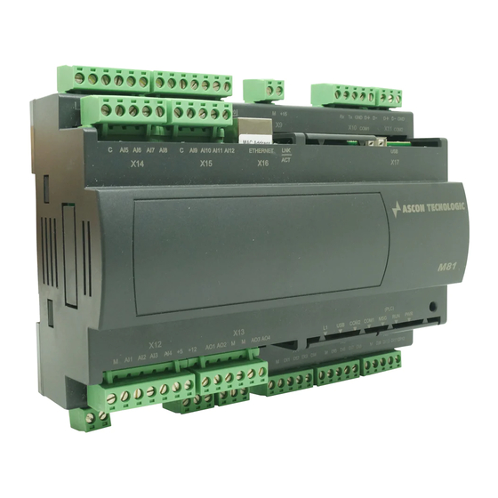
General description
11
12
13
14
15
1
Model identification label (on the back side of the module);
2
DIN RAIL 35 x 7.5 (EN50022);
3
X1 one 2 poles plug to connect the power supply and
X2... X3 two 3 poles plugs to connect the DO1...DO2 SPDT output relays or
Vdc/Vac SSR or 12 Vdc to drive external SSR;
4
X4... X6 two 5 poles plugs to connect the DI1... DI12 Digital Inputs;
5
Status/diagnostic LEDs:
L1 (red, CAN ERR)
USB (green, USB activity/CAN Run),
COM2 (green, COM2 traffic),
COM1 (green, COM1 traffic),
MSG (message),
RUN (program status run/stop),
PWR (power supply ON);
6
- Reset button;
7
X17 USB type A receptacle to connect a flash drive;
8
X10 5 poles plug to connect the COM1 service serial port (RS232/RS485);
9
X11 3 poles plug to connect the COM2 serial port (RS485);
10
X9 2 poles plug output power supply (15Vdc);
11
X7... X8 6... 7 poles plugs to connect DO3... D10 SPST output relays;
12
X14... X15 5 poles plugs to connect AI5... AI12 NTC/PT1000 Analogue Inputs;
13
X16 RJ45 plug to connect the Ethernet TCP/IP network for programming purposes
or for the MODBUS through the TCP port;
14
X13 6 poles plug to connect AO1... AO4 Analogue Outputs;
15
X12 7 poles plug to connect AI1... AI4 Analogue Inputs.
Note: The green terminals on the CPU are male connectors (pitch 5 mm), the
corresponding female plugs are snap-on connectors with screw or spring
terminals for connecting the wires.
Disposal
The appliance (or the
product) must be
disposed of separately in
compliance with the local
standards in force on
waste disposal.
M81
mod.
M . I . M 8 1 - 0 4 / 1 7 . 0 5
C o d . I S T R - M M 8 1 E N G 0 4
Installation
Manual
Contents
- General description
- Accessories
- Installation
10
4
3
24 VDC Power supply
APS2ALEDR12024 (120 W, 5.0 A),
APS2ALNDR75-24 (75 W, 3.2 A),
APS2ALMDR20-24 (20 W, 1.0 A)
Integrated system,
CPU module with
on-board I/O
mod.
M81
9
Dimensions (mm)
8
7
6
175
5
Mounting position
- Mount the module vertically;
- In order to help the ventilation flow of
air, respect the distances between
modules and walls or other modules.
Mounting position (mm)
min. 80
Accessories
Screw Terminal Blocks
APS2/M81-kITSCREW
Installation
Operating conditions
Environmental condition
Operating
110
conditions
Special
60
conditions
Rail mounting
DIN 35 x 7.5
(EN 50022)
60
Forbidden
conditions
Mounting/removing the modules
on/from the DIN rail
1
Open the 2 spring slides on the lower
part of the CPU,
the module to the rail;
2
Rotate the module downwards, then
close the 2 spring
3
Switch OFF the Power Supply
Lower the spring slide by inserting a
flat-blade screwdriver as
4
Turn and lift the module upwards to
min. 60
remove the CPU from the DIN rail.
55
Mounting the module
1
min. 100
Removing the module
3
Suggestion
B
Temperature
T
0...+50°C
Umidity:
%Rh
5... 95% Rh
non condensing
Use forced
Temperature
T
> 50°C
ventilation
%Rh
> 95% RH
Warm up
Conducting
P
Use filter
atmosphere
Corrosive
C
atmosphere
Explosive
E
atmosphere
clip the upper part of
slides;
indicated;
2
4
Advertisement
Table of Contents

Related Manuals for Ascon tecnologic M81


Summary of Contents for Ascon tecnologic M81
- Page 1 C o d . I S T R - M M 8 1 E N G 0 4 on-board I/O Installation mod. Manual Ascon Tecnologic S.r.l. via Indipendenza 56, 27029 - Vigevano (PV) Tel.: +39 0381 69871, Fax: +39 0381 698730 www.ascontecnologic.com...
- Page 2 Electrical connections Terminals connections and plugs Conn. Label Signals Conn. Label Signals Power Supply C DO3 DO4 C DO5 DO6 C DO7 DO8 C DO9 DO10 M +15 Rx Tx GND D+ D- D+ D- GND 24 Vac/ COM1 COM2 RS232 Supply Power Supply...
- Page 3 Digital Inputs Digital outputs: SPST Relays - Connectors X4, X5, X6: DI01... DI12 - Connectors X7, X8: 8 SPST NO relays Front Front digital inputs; (form A) outputs; - Isolation: 800V between channel ad - Rate: 2 A (for resistive loads); Lower side Upper side Power Supply.
- Page 4 LEDs SUGGESTED WIRES ROUTING HOW TO ORDER M81 = CPU of the Programmable Logic Controller AI and DO cables a: IN AI1..AI4 Pre-Configured - = In 0/4...20 mA 5 = In 0/1... 5 V Ratiometrics b: OUT DO1...
Need help?
Do you have a question about the M81 and is the answer not in the manual?
Questions and answers