Chapters
Table of Contents

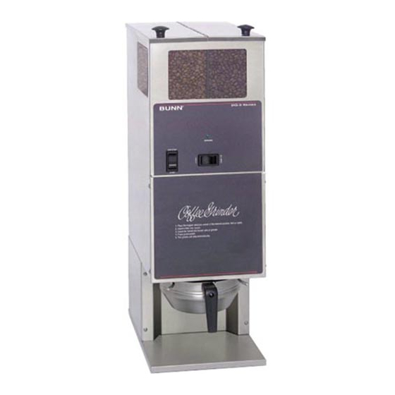
Related Manuals for Bunn DG-2


Summary of Contents for Bunn DG-2
- Page 1 BUNN ® DG-2 WDG-2 02328.0000(4) INSTALLATION & OPERATING MANUAL BUNN-O-MATIC CORPORATION POST OFFICE BOX 3227 SPRINGFIELD, ILLINOIS 62708-3227 PHONE: (217) 529-6601 FAX: (217) 529-6644 10854.0000 3/00 ©1995 Bunn-O-Matic Corporation...
-
Page 2: Table Of Contents
SPECIFIED HEREIN, TO REPAIR OR, AT BUNN’S SOLE OPTION, REPLACEMENT OR REFUND. In no event shall Bunn be liable for any other damage or loss, including, but not limited to, lost profits, lost sales, loss of use of equipment, claims of Buyer’s customers, cost of capital, cost of down time, cost of substi- tute equipment, facilities or services, or any other special, incidental or consequential damages. -
Page 3: User Notices
Carefully read and follow all notices on the grinder and in this manual. They were written for your protection. All notices on the grinder are to be kept in good condition. Replace any unreadable or damaged labels. #05876.0000 #24237.0000 #20545.0000 #05942.0000 DG-2 ONLY 10854 030300... -
Page 4: Electrical Requirements
START - (lower, momentary position) Pressing the switch to this position and releasing initiates a grind cycle. Dispense Timer - DG-2 The dispense timer controls the amount of beans that will be ground in a cycle. The timer can be adjusted to dispense a different amount from each hopper. -
Page 5: Initial Set-Up
DG-2 INITIAL SET-UP WARNING - Unplug grinder before removal of any panel. Read NOTICE attached to upper front inspection panel. Remove upper front inspection panel located below control switches and the rear panel. Remove shipping bracket, materials and discard. Reinstall upper front inspection panel and rear panel. - Page 6 SPECIAL SET-UP FOR FLAVORED COFFEE BEANS WARNING - Unplug grinder before removal of any panel. Select the hopper to be used for flavored coffee beans. Remove upper front inspection panel located below control switches. Locate dechaffer blade lever for hopper(s) se- lected in step #2.
- Page 7 10854 030300...
-
Page 8: Cleaning
The use of a damp cloth rinsed in any mild, nonabrasive, liquid detergent is recommended for cleaning all surfaces on Bunn-O-Matic equipment. Care should be taken not to scratch the hopper or windows with any abrasive material. Regular cleaning will keep your grinder looking new for years. -
Page 9: Adjustments
The following procedures should be used to make adjustments. NOTE - On DG-2 grinders a change in the burr adjustment will also change the amount dispensed. Any adjust- ment to the burrs should be followed by an adjustment of the timer, Burr Adjustment 1. - Page 10 Approx. 4.0 seconds per ounce, Medium Roast, Drip Grind. Approx. 5.5 seconds per ounce, Dark Roast, Drip Grind. Time will vary depending on bean density & grind size. Check samples by weight. DIGITAL CONTROL DISPLAY ASSEMBLY FUNCTION LIST - WDG-2 FUNCTION NO.
-
Page 11: Troubleshooting
TROUBLESHOOTING A troubleshooting guide is provided to suggest probable causes and remedies for the most likely problems encountered. If the problem remains after exhausting the troubleshooting steps, contact the Bunn-O-Matic Technical Service Department. • Inspection, testing, and repair of electrical equipment should be performed only by qualified service personnel. - Page 12 Grinder will not shut off. Grinder starts, but will not dispense from either hopper. Timer will not display or displays incorrectly. Incorrect amount of coffee. DG-2 Incorrect coffee grind dispensed. Cooling fan not running. Probable Cause 5. Motors 6. Fuse 1.
- Page 13 TROUBLESHOOTING (cont.) Problem LED will not come on when motor is running. Weigh control assembly leaking oil. WDG-2 Incorrect amount of coffee. WDG-2 WDG-2 DIGITAL DISPLAY CONTROL FAULT CODES NOTE: If the grinder stops or fails to start, the green L.E.D. should be flashing. The number of flashes corresponds to the fault code.
-
Page 14: Service
FAILURE TO COMPLY RISKS EQUIPMENT DAMAGE, FIRE, OR SHOCK HAZARD READ THE ENTIRE OPERATING MANUAL INCLUDING THE LIMIT OF WARRANTY AND LIABILITY BEFORE BUYING OR USING THIS PRODUCT 20545-0000 7/90 © 1990 Bunn-O-Matic Corporation NOTICE BUNN For connection to Bunn-Omatic Coffee Brewer Models: Dual, OT, Single, &... -
Page 15: Hopper Selector Switch
SERVICE (cont.) The hopper is attached with ten #8-32 x .25” slot- ted head locking screws. Remove hopper by lifting up and swing out the rear of the grinder to avoid scratching of windows. Off/On/Start Switch Location: The Off/On/Start switch is located to the left side on the front of the housing above the upper front inspection panel. -
Page 16: Motors
PNK TO OFF/ON/ START SWITCH VIO TO J4 - 3 WHI/ BLU TO LEFT MOTOR REAR VIEW Motors For connection to Bunn-Omatic Dual, OT, Single, & System III only. (24 volt N.E.C. Class 2 circuit only.) REAR VIEW 1. Motor Circuit Assembly 2. - Page 17 SERVICE (cont.) Motor (cont.) Test Procedure: Disconnect grinder from the power supply. Remove upper front inspection panel. Remove the two 1/4"-20 screws (A) holding the front cover (B). Remove load disc (C) from burr auger rotor/as- sembly (D). Remove burr auger rotor/spring assembly (D) from the burr housing (H).
-
Page 18: Timer
F IN rear of motor mounting bracket. P744 Test Procedure: Removal and Replacement: Timer - DG-2 Location: the lower front inspection panel. The motor circuit assembly is located on the The motor circuit assembly is a line filter for motor electrical noise. - Page 19 SERVICE (cont.) Timer - DG-2 (cont.) Test Procedure: Disconnect grinder from the power source. Slide timer with wires connected from housing. Place the hopper selector switch in the left posi- tion. Disconnect eight pin plug J4 from timer board. Check the voltage between J4-1 and J4-2 with a voltmeter.
-
Page 20: Weigh Control Board
SERVICE (cont.) Timer - DG-2 (cont.) RED TO MOTOR CIRCUIT BOARD (Prior to S/N DG00002660) WHI TO MOTOR CIRCUIT BOARD (S/N DG00002660 - UP) ORA TO OFF/ON/START SWITCH ORA TO OFF/ON/START SWITCH Weigh Control Board - WDG-2 Location The weigh control board is located on the grinder base behind the lower front inspection panel. - Page 21 SERVICE (cont.) Weigh Control Board - WDG-2 (cont.) Disconnect grinder from the power source. If voltage is present as described, proceed to #9. If voltage is not present as described, refer to the wir- ing diagram and check the grinder wiring harness. Check the voltage between J4-3 and J4-5 with a voltmeter when the "OFF/ON/START"...
- Page 22 Install a new SC 10 x .312" fuse in fuse holder. Reinstall fuse holder cap. NOTICE BUNN For connection to Bunn-Omatic Coffee Brewer Models: Dual, OT, Single, & System III only. MANUFACTURED BY BUNN-O-MATIC CORPORATION (24 volt N.E.C. Class 2 circuit only.) SPRINGFIELD, ILLINOIS, U.S.A.
- Page 23 SERVICE (cont.) L.E.D Location: The L.E.D is located on the front of the grinder just above hopper selector switch. Test Procedure: Unplug the grinder. Remove the wire nuts from both sets of wires. With a voltmeter set to read DC volts. Attach the positive (+) lead to the black and pink wires and the negative (-) lead to the gray wires.
-
Page 24: Weigh Control Assembly
SERVICE (cont.) Weigh Control Assembly - WDG-2 (cont.) 00718.0000 Front Inspection Panel Weigh Control Board and Mounting Bracket Weigh Control Mounting Bracket Weigh Control Assembly 01593.0000 Pivot Arm Funnel Rails Mounting Bracket Funnel Tab Slot in Housing Assembly P941 10854 030300... - Page 25 SERVICE (cont.) Weigh Control Assembly - WDG-2 (cont.) Removal and Replacement Disconnect grinder from the power source. Remove the four #6-32 truss head screws se- curing lower front inspection panel (1). Remove panel with digital control display assembly at- tached. Remove the one #6-32 truss head screw secur- ing the weigh control board mounting bracket (2) to the weigh assembly mounting bracket (3).
-
Page 26: Wiring Diagrams
J1-10 (OPTIONAL) BREWER INTERFACE CONNECTOR BREWER INTERFACE CONNECTOR 120 VOLTS AC 2 WIRE SINGLE PHASE 60 HZ 10856.0000B 6/97 © 1995 BUNN-O-MATIC CORPORATION SCHEMATIC WIRING DIAGRAM DG2 10 AMP WHI/RED WHI/BLU OFF/ON START SW WHI/RED SELECTOR WHI/BLU (OPTIONAL) MULTI-SET SW... - Page 27 WIRING DIAGRAMS SCHEMATIC WIRING DIAGRAM WDG2 J4-1 CIRCUIT BOARD J4-8 J1-1 J1-10 J3-1 J3-4 J5-1 J5-6 J1-1 CONTROL ASSY J1-6 TRANSDUCER ASSY 120 VOLTS AC 2 WIRE SINGLE PHASE 60 HZ 10 AMP WHI/BLU WHI/RED 10874.0000C 1/96 © 1995 BUNN_O_MATIC CORPORATION OFF/ON START SW WHI/RED...
Need help?
Do you have a question about the DG-2 and is the answer not in the manual?
Questions and answers