Table of Contents
Advertisement
TABLE OF CONTENTS
1.
2.
SAFETY INSTRUCTION .............................................................................................
3.
4.
5.
5.1 Alpha 500/520/540/560
6.
6.1 Alpha 500/520 Wiring Diagrams ..........................................................................
7.
8.
8.3 System Testing .......................................................................................................
9.
12. PARTS LIST .................................................................................................................
.......................................................................................................
.......................................................................................................
.......................................................................................................
...................................................................
...............................................................................
.......................................................................................................
.......................................................................................................
.........................................................................................
.........................................................................
.........................................................................
.................................................................................
.................................................................................
...................................................................
...................................................................................
.......................................................................................
...................................................................................
...............................................................................................
.........................................................................................
1
Page
2
3
4
5
6
6
7
8
9
10
11
12
13
14
15~16
17
17
18
19-20
21
22-23
24
Advertisement
Table of Contents

Related Manuals for Fomotech Alpha 500


Summary of Contents for Fomotech Alpha 500
-
Page 1: Table Of Contents
5.1 Alpha 500/520/540/560 ..................5.2 Alpha 500/520 Internal Assembly ................. 5.3 Alpha 540/560 Internal Assembly ................. OUTPUT CONTACT DIAGRAM 6.1 Alpha 500/520 Wiring Diagrams ................6.2 Alpha 540 Wiring Diagrams ................. 6.3 Alpha 560 Wiring Diagrams ................. SYSTEM SETTING CONFIGURATION .............. -
Page 2: Introduction
Full SMT design for system stability. The Alpha 500 series radio control system consists of a transmitter handheld, a receiver unit, and a six-foot (2-meter) output cable. The transmitter casing is molded using an industrial strength composite material which is impervious to dust, water, oil, acids, alkaline, heat, sunlight, and as well as being resistant to deformation due to long term use in harsh environments. -
Page 3: Safety Instruction
2. SAFETY INSTRUCTION The Alpha 500 systems are relatively simple to use. However, it is very important to observe the proper safety procedures during operation. When use properly the Alpha 500 systems will enhance productivity and efficiency in the workplace. -
Page 4: Pushbutton Configuration
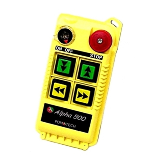
3. PUSHBUTTON CONFIGURATION 3.1 Alpha 500/520 Models Alpha 500 : Up to 2 motions, single-speed pushbuttons, EMS Stop. Alpha 520 : Up to 2 motions, dual-speed pushbuttons, EMS Stop. ON OFF STOP ON OFF STOP (Alpha 500) (Alpha 520) Below are many types of pushbutton configuration that are also available upon request. -
Page 5: Alpha 540/560
3.2 Alpha 540/560 Models 1. Alpha 540S : Up to 3 motions, single-speed pushbuttons, EMS Stop. 2. Alpha 540A : Up to 3 motions, single-speed pushbuttons, AUX, EMS Stop. 3. Alpha 540T : Up to 5 motions, single-speed pushbuttons, “Select” pushbutton for auxiliary hoist and/or trolley, EMS Stop. -
Page 6: Alpha 540T/560T "Select" Settings
Back to main hoist active. 3.4 FCC ID Labels and Numbers FCC ID: XXXALPHA504SERIES FOMOTECH INTERNATIONAL CORP. This Device complies with Part 15 of the FCC Rules. Operation is subject to the following two conditions: (1) this device may not cause harmful interference and (2) this device must accept any interference received, including interference that may cause undesired operation. -
Page 7: Transmitter Outline
4. TRANSMITTER OUTLINE 4.1 Alpha 500/520 ON OFF STOP (Fig. 1) Front View (Fig. 2) Back View (Fig. 3) Front View (Fig. 4) Back view Transmitter enclosure Pushbutton # 3 15) TX quartz crystal Power switch (ON/OFF) System information 16) Programming port... -
Page 8: Alpha 540/560
4.2 Alpha 540/560 (Fig. 5) Front View (Fig. 6) Back View (Fig. 7) Front View (Fig. 8) Back View 1) Transmitter enclosure Emergency stop (EMS) 17) Antenna 2) Power switch (ON/OFF) 10) Pushbutton #1 18) Status LED display 3) Pushbutton #2 11) Pushbutton #3 19) Battery contact 4) Pushbutton #4... -
Page 9: Receiver Outline
5. RECEIVER OUTLINE 5.1 All Models (Fig. 9) Front View (Fig. 10) Back View 1) Receiver enclosure Serial number (S/N) 2) Wiring diagram Security code (ID) 3) Contact relay LED displays* Frequency channel (CH) 4) Model (MOD) Supplied voltage (VOLT) 5) Frequency (FREQ) Anti-vibration spring Grounding (GND) -
Page 10: Alpha 500/520 Internal Assembly
5.2 Alpha 500/520 Internal Assembly (Fig. 11) Internal Parts Assembly RX module Contact output seat (CN3) Power fuse (AC) Low voltage warning fuse (LV) Spare fuses & jumpers 10) Pushbutton #3 and #4 fuse ID code dip-switch 11) AC power input seat (CN2) -
Page 11: Alpha 540/560 Internal Assembly
5.3 Alpha 540/560 Internal Assembly (Fig. 12) Internal Parts Assembly 1) RX module 10) MAIN contact fuse 2) Power fuse (AC) 11) Pushbutton #1 and #2 fuse 3) Contact output (CN3, CN4) 12) Pushbutton #3 and #4 fuse 4) Reserved contact output (CN5) 13) Pushbutton #5 and #6 fuse 5) AC power connector (CN2) 14) Low voltage fuse (Alpha 540S/560S) -
Page 12: Output Contact Diagram
6. OUTPUT CONTACT DIAGRAM 6.1 Alpha 500/520 Wiring Diagram MAIN MAIN POWER POWER (Alpha 500) (Alpha 520) No connection... -
Page 13: Alpha 540 Wiring Diagrams
6.2 Alpha 540 Wiring Diagrams MAIN MAIN MAIN LV,AUX LV,AUX LV,AUX POWER POWER POWER (Alpha 540S) (Alpha 540A) (Alpha 540T) No connection... -
Page 14: Alpha 560 Wiring Diagrams
6.3 Alpha 560 Wiring Diagrams MAIN MAIN MAIN LV,AUX LV,AUX LV,AUX POWER POWER POWER (Alpha 560S) (Alpha 560A) (Alpha 560T) No connection... -
Page 15: System Setting Configuration
Press the AUX/SELECT button to activate all transmitter key functions and the receiver MAIN after transmitter power “on” and After EMS reset Manufacture preset for all Alpha 500/520/540S/560S models Turn “on” the power switch to activate all transmitter key functions and the receiver Short MAIN. - Page 16 (Manufacture preset for the Alpha 500/520/540S/540A/560S/560A models) Transmitter MAIN Press MAIN Reset Reset MAIN Short Activated Deactivated "Power Switch" Activated * Reset Power Switch Turn the transmitter power switch “off” and then “on” again. Open Applicable (For the Alpha 540T/560T models - Manufacture preset at JP1-Open)
-
Page 17: Receiver Installation
8. RECEIVER INSTALLATION 8.1 Preparation For Installation Required Tools: (1) Flat Head Screwdriver (-) (2) Phillips Head Screwdriver (+) (3) Multi-Meter (4) 14mm Wrench x 2 (5) 10.5mm Drill-Bit Ensure receiver is not set to the same channel and ID code as any other units in operation at the same facility. -
Page 18: System Testing
8.3 System Testing Connect the power source to the receiver and test the operation of each function to ensure it operates in the same manner as the pendant controller. Ensure the receiver MAIN can be properly controlled by the remote control. Ensure the limit switches on the equipment that limit all travels are working properly. -
Page 19: Transmitter Operation
9. TRANSMITTER OPERATION Make sure the (2) alkaline batteries are installed correctly. Do make sure to use alkaline type batteries for longer operating time between battery replacements. Turn “on” the power switch located on the top left hand corner of the transmitter unit (see diagram next page). - Page 20 In case of an emergency, press down the red EMS pushbutton will immediately deactivates the receiver MAIN. When the EMS pushbutton is activated, the status LED on the transmitter unit will display a red blinking light to indicate EMS activation (ON second and OFF 0.5 second).
-
Page 21: Trouble Shooting
10. TROUBLE SHOOTING Should the operator find the equipment not operating normally, please check the chart bel o w for simple trouble shooting steps. SYMPTOM REASON SOLUTION Ensure the correct transmitter is in Transmitter does not Transmitter and the receiver are use. -
Page 22: System Specification
Source Voltage 3.0 VDC (“AA” alkaline batteries X 2) Current Drain 10 ~ 20 mA Operating Temp. ~ +70 Dimension (Alpha 500/520) 134mm X 68mm X 30.5mm Dimension (Alpha 540/560) 166mm X 67.5mm X 30mm Weight (Alpha 500/520) 7.05oz. (include batteries) Weight (Alpha 540/560) 8.82oz. - Page 23 IP-65 Source Voltage 48~380 VAC, 50/60 Hz. Power Consumption 11VA Operating Temp. ~ +70 Output Contact Rating 250V @ 10A Dimension 310mm X 134mm X 72mm Weight (Alpha 500/520) 57.3oz. (include output cable) Weight (Alpha 540/560) 60oz. (include output cable)
-
Page 24: Parts List
12. PARTS LIST TX Module/Encoder Board (Alpha 500) BEN50 TX Module/Encoder Board (Alpha 520) BEN52 TX Module/Encoder Board (Alpha 540S) BEN54S TX Module/Encoder Board (Alpha 540A) BEN54A TX Module/Encoder Board (Alpha 540T) BEN54T TX Module/Encoder Board (Alpha 560S) BEN56S TX Module/Encoder Board (Alpha 560A)
Need help?
Do you have a question about the Alpha 500 and is the answer not in the manual?
Questions and answers
How to programme