Table of Contents
Advertisement
A
l
p
A
l
p
I
n
d
u
I
n
d
u
O
O
h
a
h
a
s
t
r
i
a
l
R
a
d
s
t
r
i
a
l
R
a
p
e
r
a
t
i
o
n
p
e
r
a
t
i
o
n
Fomotech International Corp.
6
0
0
6
0
0
i
o
R
e
m
o
t
d
i
o
R
e
m
o
t
&
P
a
r
t
&
P
a
r
t
S
e
S
e
e
C
o
n
t
r
o
l
e
C
o
n
t
r
o
l
s
M
a
n
u
a
s
M
a
n
u
r
i
e
s
r
i
e
s
S
y
s
t
e
m
S
y
s
t
e
m
l
a
l
Advertisement
Table of Contents

Related Manuals for Fomotech Alpha 604A


Summary of Contents for Fomotech Alpha 604A
- Page 1 & & Fomotech International Corp.
-
Page 2: Table Of Contents
Page SAFETY INSTRUCTION ..................... PUSHBUTTON CONFIGURATION 2.1 Alpha 604 Models ....................2.2 Alpha 607 & 608 Models ..................2.3 Alpha 612 Models ....................TRANSMITTER OUTLINE 3.1 Transmitter Outline ....................3.2 Alpha 604/607/608/612 Spare Parts ............... 3.3 Battery Charger ....................RECEIVER OUTLINE 4.1 Alpha 604-608 ...................... - Page 3 10. BATTERY CHARGER 10.1 Charger Operation ....................10.2 Battery Charger LED Status Light ................. 11. TROUBLE SHOOTING....................12. SYSTEM SPECIFICATION ..................13. PARTS LIST .........................
-
Page 4: Safety Instruction
The Alpha 600 series are relatively simple to use, however, it is very important to observe the proper safety procedures before, during, and after operation. When used properly, the Alpha 600 series will enhance safety, productivity and efficiency in the workplace. The following procedures should be strictly followed: The transmitter is equipped with a specialized battery charger. -
Page 5: Pushbutton Configuration
2.1 Alpha 604 Models 1. Alpha 604A -- (4) single speed pushbuttons 2. Alpha 604B -- (4) double speed pushbuttons POWER STOP POWER STOP (Alpha 604A) (Alpha 604B) Below are some of many types of pushbutton configurations that are also available, please contact your dealer for more details. -
Page 6: Alpha 607 & 608 Models
2.2 Alpha 607 & 608 Models 1. Alpha 607A (7) single speed pushbuttons 2. Alpha 607B (6) double speed pushbuttons + (1) single speed pushbuttons 3. Alpha 607AT (6) single speed pushbuttons + (1) SELECT I/II pushbutton 4. Alpha 607BT (6) double speed pushbuttons + (1) SELECT I/II pushbutton 5. -
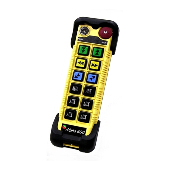
Page 7: Transmitter Outline
3.1 Transmitter Outline (Alpha 604) (Alpha 607/608) (Alpha 612) (Fig.1) Transmitter Front View (Fig.2) Transmitter encoder board and induction charging board (Fig.3) Transmitter Internal Assembly: (1) Internal antenna (2) Status LED display (3) Battery contact (4) Transmitter induction charging port (5) Programming port (6) Function dip-switch (7) JP2 setting pin... -
Page 8: Alpha 604/607/608/612 Spare Parts
3.2 Alpha 604/607/608/612 Spare Parts (1) Charging cable (2) Charger (optional) (3) Transmitter shock-absorbing rubber (4) Shoulder strap (5) Rechargeable batteries (optional) 3.3 Battery Charger (1) Charger power status: green light (2) Charging status: green/red light (3-1) Power input socket AC100-240V (3-2) Power input socket DC12-24V (4) Charger holder (optional). -
Page 9: Receiver Outline
SIZE:310mm X 134mm X 72mm EN ISO 13849-1:2008, PLd 60947 EMS HOIST F2 5A COM1 TROLLEY F3 5A COM2 BRIDGE F4 5A COM3 LV/AUX1 14 LV /AUX2 AUX1 AUX2 F5 5A COM4 MAIN MAIN COM5 L1(X1) POWER L2(X2) GRN/YEL Anti-vibration spring must be grounded MOD: I D:... -
Page 10: Alpha 604 Models Internal Assembly
(Fig. 7) Internal Parts Assembly Receiving RF module Power module * Secondary power AC fuse (F1) Primary power AC fuse (FF1) System status LED display* External antenna port ID code dip-switch RF channel dip-switch Contact relay LED display 10) Pushbutton #1 and #2 fuse (5.0A) 11) MAIN fuse (5.0A) Contact output seat (CN3) 13) Low-voltage (LV) fuse (5.0A) -
Page 11: Alpha 607/607 Models Internal Assembly
(Fig. 8) Internal Parts Assembly 1) Receiving RF module 2) External programming port 3) Power module 4) Secondary power AC fuse (F1) 5) Contact output seat (CN8) 6) Primary power AC fuse (FF1) 7) AC power input seat (CN2) 8) Internal Antenna 9) System Status LED display* 10 )External antenna port 11) ID code dip-switch... -
Page 12: Alpha 612 Models External Assembly
SIZE:300mm X 230mm X 86mm (Fig. 9) External Parts Assembly Transparent top cover Mounting bracket with shock absorbers Light-gray colored base Cable gland / Cord grip - 11 -... -
Page 13: Alpha 612 Models External/Internal Assembly
(Fig. 10) Internal Parts Assembly 1) Power LED display* 12) Pushbutton #1 and #2 relay fuse (5.0A) 2) SQ LED display** 13) Receiving RF module or PLL (Phase Lock Loop) 3) Status LED display**** 14) External antenna port 4) DC power relay LED display*** 15) RF channel dip-switch 5) Programming port 16) ID code dip-switch... -
Page 14: Α604/Α608/Α612 Receiver Power Fuse List
α α α α α α Voltage Type Parts No. AC100~120 AC220~240 AC380~440 AC100~240V DC12V~24V AC24 AC36~48V Full-V oltage α604 α608 0.5A α612 0.8A - 13 -... -
Page 15: Output Contact Diagrams
(Alpha 604A) (Alpha 604B) MAIN MAIN FOM TECH POWER POWER ( Alpha 607A) (Alpha 607B) HOIST HOIST F2 5A F2 5A COM1 COM1 TROLLEY TROLLEY F3 5A F3 5A E/W2 COM2 COM2 BRIDGE BRIDGE F4 5A F4 5A N/S2 COM3... -
Page 16: Alpha 608 Models
( Alpha 607AT) (Alpha 607BT) HOIST HOIST F2 5A F2 5A COM1 COM1 TROLLEY TROLLEY F3 5A E/W2 F3 5A COM2 COM2 BRIDGE BRIDGE F4 5A N/S2 F4 5A COM3 COM3 LV/SEL-I LV/SEL-I 14 LV /SEL-II /SEL-II SEL-I SEL-I SEL-II SEL-II F5 5A F5 5A... - Page 17 ( Alpha 608AT) (Alpha 608BT) HOIST HOIST F2 5A POWER STOP F2 5A COM1 COM1 TROLLEY TROLLEY F3 5A E/W2 F3 5A COM2 COM2 BRIDGE BRIDGE F4 5A F4 5A N/S2 COM3 COM3 SEL-II/AUX1 SEL-II/AUX1 SEL-II SEL-II /SEL-I /SEL-I AUX1 AUX1 SEL-I F5 5A...
-
Page 18: Alpha 612 Models
(Alpha 612A) FOM TECH (Alpha 612B) POWER STOP - 17 -... - Page 19 (Alpha 612C-1) FOM TECH (Alpha612C-2) FOM TECH - 18 -...
- Page 20 (Alpha 612D) FOM TECH (Alpha 612E-1) POWER STOP - 19 -...
- Page 21 (Alpha 612E-2) POWER STOP - 20 -...
-
Page 22: How To Set Id Codes
6.1.1 Set by programming tool 6.1.2 Set by encoder board JP1, 1 pin and dip-switch Setting Steps: (1) Rotate the transmitter power to OFF position (2) Remove the transmitter shock-absorbing rubber (3) Place the transmitter pushbutton side downward and unscrew the transmitter bottom casing. (4) Set the transmitter ID code with the dip-switch on the encoder board and put jumper on the 1 pin of JP1. -
Page 23: Transmitter Rf Channel Setting
Transmitter channel settings (Select the channel you would like to operate. Do not exceed the channel limit) 6.2.1 Set by programming tool 6.2.2 Set by encoder board 2 & 3 pin of JP1 and dip-switch To set the frequency on JP1 of TX board, put jumper on 2 &... -
Page 24: Receiver Rf Channel Settings
α α Please refer to Fig. 18 Internal Parts Assembly (Page 11) for 8-position ID code dip-switch to set receiver ID code. Top slot “1”; bottom slot “0” Set the ID codes needed on the decoder board dip-switch. For example: the ID codes → 10010110 (“1”... -
Page 25: Receiver Function Settings
7.3 Receiver Function Settings 7.3.1 α604/607/608 Receiver Function Settings 7.3.1.1 Set by programming tool 7.3.1.2. Adjust Jumper setting function by decoder board Adjusting jumper setting to change function selection (refer to Jump Set table as below): JP1 => α607A/B/608: MODE 0: Start the system either by AUX pushbutton (No.7 pushbutton) or power switch. -
Page 26: Α612 Receiver Function Settings
* 4 pushbuttons: When either relay of pushbutton 1~4 is activated, LV relay will also be activated. * 8 pushbuttons: When either relay of pushbutton 1~6 is Short activated, LV relay will also be activated. * 12 pushbuttons: When either relay of pushbutton 1~8 is activated, LV relay will also be activated. -
Page 27: Α612 Models Dip-Switch Function Table
7.3.3 Alpha 612 Models Dip-Switch Function Table Model Pushbutton Dip-Switch Setting Description 1 & 2 → 1 Not Interlocked 3 & 4 DIP 1 → 0 Interlocked 5 & 6 → 1 Not Interlocked 7 & 8 DIP 2 → 0 Interlocked 612A →... - Page 28 DIP 2,3 → 00 Momentary relay contact DIP 2,3 → 01 Latching/toggle relay contact DIP 2,3 → 10 Activate the 3 speed → 1 Latching/toggle relay contact DIP 4 → 0 Momentary relay contact Both 1 and 2 speed contact Both 1 and 2 speed...
-
Page 29: Α612 Receiver Voltage Settings
7.3.4 Alpha 612 Receiver Voltage Settings 1. Select the voltage of the place where the receiver is installed. 2. Select the position of the “Y” terminal base on the label marked on the transformer. If the default voltage setting is different from the place where the receiver is installed, please change the setting base on below steps: Please first refer to below figure. -
Page 30: Frequency (Rf) Channels Table
Band 301MHz Dip-Switch Setting Channel Band 301MHz Dip-Switch Setting Channel 301.955 MHz 301.105 MHz 00000001 00100011 301.980 MHz 301.130 MHz 00000010 00100100 302.005 MHz 301.155 MHz 00000011 00100101 302.030 MHz 301.180 MHz 00000100 00100110 302.055 MHz 301.205 MHz 00000101 00100111 302.080 MHz 301.230 MHz 00000110... - Page 31 Band 433MHz Dip-Switch Setting Channel Band 433MHz Dip-Switch Setting Channel 433.075 MHz 00000001 434.425 MHz 00100011 433.100 MHz 00000010 434.450 MHz 00100100 433.125 MHz 00000011 434.475 MHz 00100101 433.150 MHz 00000100 434.500 MHz 00100110 433.175 MHz 00000101 434.525 MHz 00100111 433.200 MHz 00000110 434.550 MHz...
-
Page 32: Transmitter Operating Steps
& & 8.1 Transmitter Operating Steps 1. Make sure the two “AA” NiMH rechargeable batteries are installed correctly. Please note the polarity of the batteries. 2. Status lights _To operate the transmitter, please rotate the power key on the top-left corner clockwise to “on”... -
Page 33: Transmitter Status Light
Power status light STOP: press → lock STOP : Elevate clockwise → reset (Turn on the transmitter at any time) (emergency stop) 8.2 Transmitter Status Light Type Status Problem LED Indication Place transmitter into Charging Constant red light ON charger Power on when voltage is Blinking red light flash BATT<2.2V... -
Page 34: Receiver Installation
Activate MSSI/FSI function: Blinking red light, green light FSI mode Depress FAN+SAFETY ON_0.1/OFF_0.1 second button and hold for more than 2 seconds. Normal operation Press pushbutton Green light flash ON_0.1/OFF_1.9 sec Remark: Under high temperature protection, press every pushbutton will send null commands and the corresponding pushbutton relay will be unlatched. - Page 35 If it is unavoidable, please consider using antenna with external coaxial cable to relocate the antenna to better signal receipt position. 3. Always locate the receiver unit as far away from high voltage wiring or equipment, such as: motor, relay, magnetic valve, inverter controls and output cable…etc. as possible. Be sure to install the receiver at least 2 meters away from the inverter.
-
Page 36: System Testing
1. Connect the power source to the receiver and test the MAIN relay output by pressing the red emergency stop button (EMS) and observe that it properly opens and closes the main line disconnect contactor. 2. Test the operation of each function to ensure it corresponds to the transmitter direction labels and/or the pendant it is replacing. - Page 37 Receiver system Status LED Display Type Led Indication Problem and Solution EEPROM error – reprogramming required. Constant red light. Incorrect receiver ID code setting (see note below). ON → 1.0 second ID code not matched on both the transmitter and OFF →...
-
Page 38: Battery Charger
10.1 Charger Operation Electromagnetic Induction Charge The electromagnetic induction charger with undisclosed metal charging contacts on transmitter provides immediate charging simply by sliding the transmitter into the charger. It is not necessary to open the battery cover to replace batteries. To avoid rain, high temperature, humidity and corroding air, please place or install the battery charger ... - Page 39 When the rechargeable batteries are placed under low temperature environment, the activity is low and the “charging completed” LED will display in a shorter time than usual. To avoid such condition, please recharge the batteries within 0 ~ 40℃. Under lower temperature environment (below 0℃), the running down batteries will complete charging within half an hour.
-
Page 40: Battery Charger Led Status Light
10.2 Battery Charger LED Status Light Item Status Condition Status Light Startup check Within 2 seconds after power is on Red + Green LED for 2 sec No battery inside transmitter battery Charging failed holder or non-rechargeable battery is Red LED OFF_0.1/ON_1.9 sec used. -
Page 41: System Specification
Transmitter Unit Source Voltage Ni-MH AA size x 2 battery 2.4V (no contact charging) Or AA alkaline x 2 batteries 3.0V Antenna Impedance Internal Antenna 50 ohms. External antenna is available. Dimension 604 Models : 140mm x 68mm x 30mm 607, 608 Models: 189mm x 68mm x 30mm 612 Models : 235mm x 68mm x 30mm... - Page 42 Receiver Unit Frequency Band BRXN – 301, 433 MHz Channel Spacing 25KHz (BRX-301, 433) Frequency Control VTCXO (PLL) Frequency Drift < 5ppm @ -20℃ ~ +70℃ Frequency Deviation < 1ppm @ 25℃ Sensitivity <-115dBm Spurious Emission - 50dB Antenna Impedance 50 ohms Responding Time 40ms (Normal)
-
Page 43: Parts List
1. Transmitter RF module (Alpha 604) BTX433 2. Encoder board (Alpha 604A) BEN604A Encoder board (Alpha 604B) BEN604B Encoder board (Alpha 607A) BEN607A Encoder board (Alpha 607B) BEN607B Encoder board (Alpha 607AT) BEN607AT Encoder board (Alpha 607BT) BEN607BT Encoder board (Alpha 608A) - Page 44 Transformer (230VAC – Alpha 600-608) T230VAC Transformer (240VAC – Alpha 600-608) T240VAC Transformer (380VAC – Alpha 600-608) T380VAC Transformer (25/36/42/50VAC – Alpha 612) T25/36/42/50V AC Transformer (110/240VAC – Alpha 612) T110/240VAC Transformer (380/460VAC – Alpha 612) T380/460VAC 8. Full voltage module (100-240VAC-Alpha 600-608) FV100-240VAC OC607 2-meter Output Cable with 5 Common Circuits Cable...
Need help?
Do you have a question about the Alpha 604A and is the answer not in the manual?
Questions and answers