Table of Contents
Advertisement
T
T
1.
INTRODUCTION .......................................................................................................
2.
SAFETY INSTRUCTION .............................................................................................
3.
3.1 Alpha 500 & 520 Models .....................................................................................
3.2 Alpha 540 & 560 Models .....................................................................................
4.
4.1 Alpha 500 & 520 Models .....................................................................................
4.2 Alpha 540 & 560 Models .....................................................................................
5.
5.1 Alpha 500 ~ 560 Models External Assembly .......................................................
5.2 Alpha 500 & 520 Models Internal Assembly .......................................................
5.3 Alpha 540 & 560 Models Internal Assembly .......................................................
5.4 Alpha 580 Models External Assembly .................................................................
5.5 Alpha 580 Models Internal Assembly .................................................................
6.
6.1 Alpha 500 & 520 Models .....................................................................................
6.2 Alpha 540 Models .................................................................................................
6.3 Alpha 560 Models .................................................................................................
6.4 Alpha 580 Models .................................................................................................
7.
7.2 How to Set ID Codes .............................................................................................
7.4 How to Remove the Transmitter RF Board .........................................................
7.5 Alpha 580 Pushbutton Function Settings .............................................................
7.6 Frequency (RF) Channel Table .............................................................................
8.
8.1 Preparation For Installation ...................................................................................
8.2 Step-By-Step Installation .......................................................................................
8.3 System Testing .......................................................................................................
9.
TRANSMITTER OPERATION ...................................................................................
10. TROUBLE SHOOTING ...............................................................................................
11. SYSTEM SPECIFICATION .........................................................................................
12. PARTS LIST .................................................................................................................
A
B
L
E
O
F
A
B
L
E
O
F
...............................................................................................
...............................................................................................
.............................................................................
.............................................................................
C
O
N
T
E
N
C
O
N
T
E
N
1
T
S
T
S
Page
2
3
4
5
6
7
8
9
10
11
12
13
14
15
16
17
18~20
21~22
22
23
23
24~25
26
27
27
28
29~31
32
33
34~35
Advertisement
Table of Contents

Related Manuals for Fomotech Alpha 500


Summary of Contents for Fomotech Alpha 500
-
Page 1: Table Of Contents
4.3 Alpha 580 Models ....................RECEIVER OUTLINE 5.1 Alpha 500 ~ 560 Models External Assembly ............5.2 Alpha 500 & 520 Models Internal Assembly ............5.3 Alpha 540 & 560 Models Internal Assembly ............5.4 Alpha 580 Models External Assembly .............. -
Page 2: Introduction
The system incorporates numerous redundant safety circuits that guaranty maximum security and ensure the system is resistant to outside interference. The major features of the Alpha 500 series are as follow:... -
Page 3: Safety Instruction
Do not use the same RF channel and ID code as any other system in use at the same facility or within 300-meter distance. Ensure the wrist strap (Alpha 500 ~ 560 models) or the waist belt (Alpha 580 models) is worn at all time during operation to avoid accidental damage to the transmitter. -
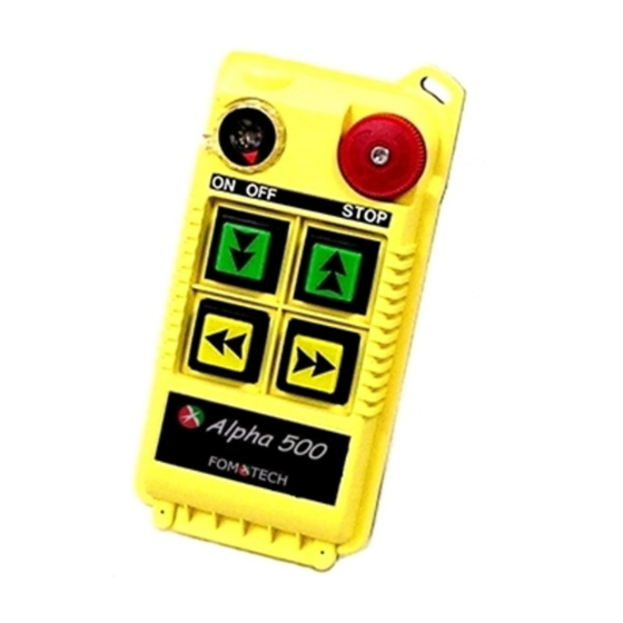
Page 4: Pushbutton Configuration
& & Alpha 500 : (4) one-speed pushbuttons. Alpha 520 : (4) two-speed pushbuttons. ON OFF STOP ON OFF STOP (Alpha 500) (Alpha 520) Below are some of many types of pushbutton configurations that are also available, please contact your dealer for more details. -
Page 5: Alpha 540 & 560 Models
& & 1. Alpha 540S : (6) one-speed pushbuttons. 2. Alpha 540A : (6) one-speed pushbuttons + (1) AUX micro-button. 3. Alpha 560S : (6) two-speed pushbuttons. 4. Alpha 560A : (6) two-speed pushbuttons + (1) AUX micro-button. (Alpha 540S) (Alpha 540A) (Alpha 560S) (Alpha 560A) -
Page 6: Alpha 580 Models
1. Alpha 580A-1 : (10) one-speed pushbuttons (labeled as 3 motions). 2. Alpha 580A-2 : (10) one-speed pushbuttons (labeled as 4 motions). 3. Alpha 580B : (9) one-speed pushbuttons + (1) SELECT I/II pushbutton.* 4. Alpha 580C-1 : (6) two-speed + (4) one-speed pushbuttons. 5. -
Page 7: Transmitter Outline 4.1 Alpha 500 & 520 Models
& & ON OFF STOP (Fig. 1) Front View (Fig. 2) Back View (Fig. 3) Front View (Fig. 4) Back View Transmitter enclosure Pushbutton # 3 (→ / East) 15) Programming port Power switch (ON/OFF) System information 16) ID code dip-switch Pushbutton #2 (↓... -
Page 8: Alpha 540 & 560 Models
& & (Fig. 5) Front View (Fig. 6) Back View (Fig.7) Front View (Fig. 8) Back View Transmitter enclosure Pushbutton #1 (↑ / Up) 15) Status LED display Power switch (ON/OFF) Pushbutton #3 (→ / East) 16) Battery contact Pushbutton #2 (↓ / Down) 10) Pushbutton #5 (↗... -
Page 9: Alpha 580 Models
(Fig. 9) Front View (Fig. 10) Back View (Fig. 11) Front View (Fig. 12) Back View Transmitter enclosure Waist belt attachment 17) Battery cover screws External antenna port Emergency stop (EMS) 18) Battery cover Power switch (ON/OFF) Pushbutton #1 (↑ / Up) 19) Internal antenna Pushbutton #2 (↓... -
Page 10: Receiver Outline
MAIN LV,AUX AC220V 50/60HZ POWER Anti-vibration spring must be grounded (Fig. 13) Front View (Fig. 14) Back View Receiver enclosure System frequency Supplied voltage Wiring diagram System serial number 10) Anti-vibration spring Receiver LED displays* System ID code 11) Grounding (GND) Type model System RF channel AUX Relay Contact Indicator (for Alpha 540A/560A models only). -
Page 11: Alpha 500 & 520 Models Internal Assembly
& & (Fig. 15) Internal Parts Assembly Receiving RF module Secondary power AC fuse (0.50A) Primary power AC fuse (1.0A) System status LED display* External antenna port ID code dip-switch RF channel dip-switch Contact relay LED display Pushbutton #1 and #2 fuse (5.0A) 10) MAIN fuse (5.0A) 11) Contact output seat (CN3) 12) Low-voltage (LV) fuse (5.0A) -
Page 12: Alpha 540 & 560 Models Internal Assembly
& & (Fig. 16) Internal Parts Assembly Receiving RF module External programming port Secondary power AC fuse (0.50A) Contact output seat (CN8) Primary power AC fuse (1.0A) AC power input seat (CN2) Internal Antenna System Status LED display* External antenna port 10) ID code dip-switch 11) RF channel dip-switch 12) Contact relay LED display... -
Page 13: Alpha 580 Models External Assembly
(Fig. 17) External Parts Assembly Transparent top cover Mounting bracket with shock absorbers Light-gray colored base Cable gland / Cord grip... -
Page 14: Alpha 580 Models Internal Assembly
(Fig. 18) Internal Parts Assembly 1) Power LED display* 12) Pushbutton #1 and #2 relay fuse (5.0A) 2) SQ LED display** 13) Receiving RF module 3) Status LED display**** 14) External antenna port 4) DC power relay LED display*** 15) RF channel dip-switch 5) Programming port 16) ID code dip-switch 6) Jumper settings... -
Page 15: Output Contact Diagrams
& & (Alpha 500) (Alpha 520) MAIN MAIN POWER POWER... -
Page 16: Alpha 540 Models
(Alpha 540S) (Alpha 540A) MAIN MAIN LV,AUX LV,AUX POWER POWER... -
Page 17: Alpha 560 Models
(Alpha 560S) (Alpha 560A) MAIN MAIN LV,AUX LV,AUX POWER POWER... - Page 18 (Alpha 580A-1) & (Alpha 580A-2) Note: The output contact diagram for both Alpha 580A-1 and Alpha 580A-2 models are identical, the only difference is the transmitter pushbutton labeling. (Alpha 580B)
- Page 19 (Alpha 580C-1) & (Alpha 580C-2) Note: For Alpha 580C-1 model, please disregard “A1.2 + 2.2” terminal output. (Alpha 580D)
- Page 20 (Alpha 580E) (Alpha 580F)
-
Page 21: System Configurations
DIP-SW OPEN→JUMP SHORT→JUMP (Fig. 19) Alpha 500 ~ 560 Models (Fig. 20) Alpha 580 Models Manufacture Settings For Alpha 580 models only 1. After turning “on” the transmitter power, press START/AUX pushbutton to activate the receiver MAIN. Open 2. After EMS Reset, press START/AUX pushbutton to activate the receiver MAIN. -
Page 22: How To Set Id Codes
JP-1 Setting (for Alpha 580 models only) Power Press START/AUX Receiver MAIN Press START/AUX Receiver MAIN Reset EMS button Open “On” pushbutton activated pushbutton activated Power Receiver MAIN activated Reset EMS button Receiver MAIN activated Short “On” JP-3 Setting (for all models) Work resumes Transmitter Power... -
Page 23: Receiver Rf Channel Setting
There are 30 sets of user-adjustable receiving RF channels that can be set manually via a 5-position dip-switch located to the right of the receiving RF module. Change the receiving RF channel simply by resetting these 5-position dip-switch. For the location of the receiving RF module, please refer to fig. - Page 24 Numerous Alpha 580 models’ pushbutton contact relay settings can be set via an 8-position dip-switch located on the receiver decoder/relay board (refer to fig. 18 on page 14). DIP-1 “0” → Example: DIP-2 “1” → DIP-3 “1” → DIP-4 “0” →...
- Page 25 Alpha 580 models dip-switch function table (continued) DIP1 → “0” → pushbutton 1&2 with both 1 and 2 speed contact relay activated when pressed to 2 speed (refer to note A) “1” → pushbutton 1&2 with both 1 and 2 speed contact relay interlocked when pressed to 2 speed (refer to note B)
-
Page 26: Frequency (Rf) Channel Table
FREQUENCY DIP-SWITCH SETTING RF CHANNEL 301.105 MHz 00001 301.130 MHz 00010 301.155 MHz 00011 301.180 MHz 00100 301.205 MHz 00101 301.230 MHz 00110 301.255 MHz 00111 301.280 MHz 01000 301.305 MHz 01001 301.330 MHz 01010 301.355 MHz 01011 301.380 MHz 01100 301.405 MHz 01101... -
Page 27: Receiver Installation
If a crane or equipment’s runway is longer than 100 meters, an external antenna should be added. The Alpha 500 series’ receiver housing has provisions for an external factory installed antenna available as an option, contact your dealer for price and delivery. -
Page 28: System Testing
(Fig. 21) Alpha 500 ~ 560 Models 2 5 5 mm 4 - O10.5 2 7 8 mm (Fig. 22) Alpha 580 Models Connect the power source to the receiver and test the MAIN relay output by pressing the red emergency stop button (EMS) and observe that it properly opens and closes the main line disconnect contactor. -
Page 29: Transmitter Operation
Startup Procedure _ There are two types of transmitter power key-switch available for the Alpha 500 series, the standard fixed type (refer to fig. 23) and the optional removable type (refer to fig. 24). Basically both key types operate in the same fashion depending on personal preference and safety regulations. - Page 30 Status Lights _ If the transmitter Status LED displays a red blinking light that is “on” → 0.1 second and “off” → 2.0 seconds, or no light at all, this indicates that the two “AA” batteries in the transmitter must be replaced. For battery replacement please refer to instruction next page. If the transmitter Status LED is blinking red, “on”...
- Page 31 (+) charge and which side is negative (-). After changing the batteries, make sure all screws are tightened. Transmission Data _ The data of the Alpha 500 series are carried out by the power-saving PCDT method of transmission (Pause Continuous Data Transmission). The duration of each PCDT transmission is set at 40 seconds, with option for 3 minutes (please contact your dealer for more details).
-
Page 32: Trouble Shooting
Should the operator find the equipment not operating normally, please check the chart below for simple trouble shooting tips. PROBLEM POSSIBLE REASON SOLUTION Ensure the correct transmitter is Transmitter does Transmitter and the receiver are in use. The labels on the receiver not communicate not on the same RF channel and the transmitter will identify the... -
Page 33: System Specification
-120dBm Antenna Impedance 50ohms Data Decoder Reference Quartz Crystals Responding Time 40ms (Normal) Enclosure Rating IP-65 (Alpha 500~560 Models) IP-66 (Alpha 580 Models) Source Voltage AC 220V ~ 230V @ 50/60 Hz. Power Consumption 11VA Operating Temperature -25℃ ~ +75℃... -
Page 34: Parts List
Decoder/Relay Board (Alpha 580D) BDR580D Decoder/Relay Board (Alpha 580E) BDR580E Decoder/Relay Board (Alpha 580F) BDR580F Transmitter Enclosure (Alpha 500 & 520 Models) BCT500 Transmitter Enclosure (Alpha 540S & 560S Models) BCT560S Transmitter Enclosure (Alpha 540A & 560A Models) BCT560A Transmitter Enclosure (Alpha 580A, C, D Models) - Page 35 15. Leather Pouch (Alpha 500 ~ 520 Models) LP500 Leather Pouch (Alpha 540 ~ 560 Models) LP560 16. 2-meter Output Cable with 1 Common Circuit (Alpha 500 ~ 560 Models) OC500 2-meter Output Cable with 1 Common Circuit (Alpha 540 ~ 560 Models) OC501...
Need help?
Do you have a question about the Alpha 500 and is the answer not in the manual?
Questions and answers
how to set the channel frequency on alpha 560a to channel405 frequency 433.1750 thanks