Table of Contents
Advertisement
A
l
p
h
A
l
p
h
I
n
d
u
s
I
n
d
u
s
O
O
a
6
0
a
6
0
t
r
i
a
l
R
a
d
i
t
r
i
a
l
R
a
d
i
p
e
r
a
t
i
o
n
p
e
r
a
t
i
o
n
Fomotech International Corp.
0
X
S
0
X
S
o
R
e
m
o
t
e
o
R
e
m
o
t
e
&
P
a
r
t
s
&
P
a
r
t
s
S
e
r
S
e
C
o
n
t
r
o
l
S
y
C
o
n
t
r
o
l
S
y
M
a
n
u
a
l
M
a
n
u
a
l
i
e
s
r
i
e
s
s
t
e
m
s
t
e
m
Advertisement
Table of Contents

Related Manuals for Fomotech Alpha 600XS Series


Summary of Contents for Fomotech Alpha 600XS Series
- Page 1 & & Fomotech International Corp.
-
Page 2: Table Of Contents
Page SAFETY INSTRUCTION ..................... PUSHBUTTON CONFIGURATION Alpha 604 Models ..................Alpha 607 & 608 Models ..................Alpha 612 Models ....................TRANSMITTER OUTLINE 3.1 Transmitter Outline ..................3.2 Alpha 604/607/608/612 Spare Parts ..............3.3 Charger Assembly ....................RECEIVER OUTLINE 4.1 Alpha 604-608 4.1.1 Alpha 604-608 Models External Assembly ............ - Page 3 RECEIVER INSTALLATION 9.1 Preparation For Installation ................... 9.2 Step-By-Step Installation ..................9.2.1 Select the location ..................9.2.2 Commissioning steps ..................9.3 System Testing ....................... 9.4 Receiver System Status LED Display..............10. BATTERY CHARGER 10.1 Charger Operation ....................10.2 Battery Charger LED Status Light ................. 11.
-
Page 4: Safety Instruction
The Alpha 600XS series are relatively simple to use, however, it is very important to observe the proper safety procedures before, during, and after operation. When used properly, the Alpha 600XS series will enhance safety, productivity and efficiency in the workplace. -
Page 5: Pushbutton Configuration
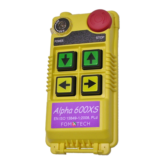
2.1 Alpha 604 Models 1. Alpha 604AS (4) single speed pushbuttons 2. Alpha 604BS (4) double speed pushbuttons POWER STOP POWER STOP POWER STOP POWER STOP 上 下 上 下 東 西 東 西 EN ISO 13849-1:2008, PLd EN ISO 13849-1:2008, PLd FOM TECH FOM TECH (Alpha 604AS) -
Page 6: Alpha 607 & 608 Models
2.2 Alpha 607 & 608 Models 1. Alpha 607AS (7) single speed pushbuttons 2. Alpha 607BS (6) double speed pushbuttons + (1) single speed pushbuttons 3. Alpha 607ATS (6) single speed pushbuttons + (1) SELECT I/II pushbutton 4. Alpha 607BTS (6) double speed pushbuttons + (1) SELECT I/II pushbutton 5. -
Page 7: Transmitter Outline
3.1 Transmitter Outline (Alpha 604) (Alpha 607/608) (Alpha 612) (Fig.1) Transmitter Front View (Fig.2) Transmitter encoder board and induction charging board (Fig.3) Transmitter Internal Assembly (1) Internal antenna (6) Programming port (2) Transmitting RF module (7) E-stop connecting port (3) Status LED display (8) Function dip-switch (4) Battery contact (9) JP2 setting pin... -
Page 8: Alpha 604/607/608/612 Spare Parts
3.2 Alpha 604/607/608/612 Spare Parts (1) Charging cable (2) Charger (charging cable included, optional) (3) Transmitter shock-absorbing rubber (4) Shoulder strap (5) Rechargeable batteries (optional) 3.3 Charger Assembly (1) Charger power status: green light (2) Charging status: green/red light (3-1) Power input socket AC100-240V (3-2) Power input socket DC12-24V (4) Charger holder (optional). -
Page 9: Receiver Outline
SIZE:310mm X 134mm X 72mm EN ISO 13849-1:2008, PLd 60947 EMS HOIST F2 5A COM1 TROLLEY F3 5A COM2 BRIDGE F4 5A COM3 LV/AUX1 14 LV /AUX2 AUX1 AUX2 F5 5A COM4 MAIN MAIN COM5 L1(X1) POWER L2(X2) GRN/YEL Anti-vibration spring must be grounded MOD: I D:... -
Page 10: Alpha 604 Models Internal Assembly
(Fig. 7) Internal Parts Assembly Receiving RF module External programming port(CN5)**** Power module * Secondary power AC fuse (F1)** Primary power AC fuse (FF1)** External programming port(CN9)**** Receiving antenna System status LED display*** External antenna port 10) ID code dip-switch 11) RF channel dip-switch 12) Contact relay LED display 13) Pushbutton #1 and #2 fuse (5.0A) -
Page 11: Alpha 607/607 Models Internal Assembly
(Fig. 8) Internal Parts Assembly 1) Receiving RF module 2) External programming port(CN5) **** 3) Power module 4) Secondary power AC fuse (F1)** 5) Contact output seat (CN8) 6) Primary power AC fuse (FF1) ** 7) AC power input seat (CN2) 8) External programming port(CN9) **** 9) Internal Antenna... -
Page 12: Alpha 612 Models External Assembly
SIZE:300mm X 230mm X 86mm (Fig. 9) External Parts Assembly Transparent top cover Mounting bracket with shock absorbers Light-gray colored base Cable gland / Cord grip - 11 -... -
Page 13: Alpha 612 Models External/Internal Assembly
(Fig. 10) Internal Parts Assembly 1) Power LED display* 14) Receiving antenna (see below 4.3) 2) SQ LED display** 15) Third power fuse FF2 3) Status LED display**** 16) Receiving RF module 4) Relay power LED display 17) External antenna port 5) Programming port (CN3)***** 18) RF channel dip-switch 6) Programming port (CN5)*****... -
Page 14: Alpha 604/608/612 Receiver Power Fuse List
Voltage Type Parts No. AC100~120 AC220~240 AC380~440 AC100~240V DC12V~24V AC24 AC36~48V Full-Voltage α604 α607 0.5A α608 α612 0.8A - 13 -... -
Page 15: Output Contact Diagrams 5.1 Alpha 604 Models Double Output
POWER STOP EN ISO 13849-1:2008, PLd FOM TECH Relay Description MAIN 1 MAIN relay 1 MAIN 2 MAIN relay 2 ‘U’ 1-speed ‘U’ 2-speed ‘D’ 1-speed ‘D’ 2-speed ‘E’ 1-speed ‘W’ 1-speed ‘E’ & ‘W’ 2-spped Transmitter low voltage - 14 -... -
Page 16: Alpha 607 Models Double Output
POWER STOP EN ISO 13849-1:2008, PLd FOM TECH Relay Description ‘U’ 1-speed ‘U’ 2-speed ‘D’ 1-speed ‘D’ 2-speed ‘E’ 1-speed ‘W’ 1-speed ‘E’ & ’W’ 2-speed E/W2 ‘N’ 1-speed ‘S’ 1-speed ‘N’& ’S’ 2-speed N/S2 Transmitter low voltage ’AUX1’ AUX1 MAIN 1 MAIN relay 1 MAIN 2... - Page 17 POWER STOP EN ISO 13849-1:2008, PLd FOM TECH Relay Description ‘U’ 1-speed ‘U’ 2-speed ‘D’ 1-speed ‘D’ 2-speed ‘E’ 1-speed ‘W’ 1-speed ‘E’ & ‘W’ 2-speed E/W2 ‘N’ 1-speed ‘S’ 1-speed ‘N’ & ’S’ 2-speed N/S2 Transmitter low voltage ‘SELECT I’ SEL-I ‘SELECT II’...
-
Page 18: Alpha 608 Models Double Output
POWER STOP EN ISO 13849-1:2008, PLd FOM TECH Relay Description ‘U’ 1-speed ‘U’ 2-speed ‘D’ 1-speed ‘D’ 2-speed ‘E’ 1-speed ‘W’ 1-speed ‘E’ & ’W’ 2-speed E/W2 ‘N’ 1-speed ‘S’ 1-speed ‘N’& ’S’ 2-speed N/S2 Transmitter low voltage ‘AUX1’ AUX1 ‘AUX2’... - Page 19 POWER STOP EN ISO 13849-1:2008, PLd FOM TECH Relay Description ‘U’ 1-speed ‘U’ 2-speed ‘D’ 1-speed ‘D’ 2-speed ‘E’ 1-speed ‘W’ 1-speed ‘E’ & ‘W’ 2-speed E/W2 ‘N’ 1-speed ‘S’ 1-speed ‘N’ & ‘S’ 2-speed N/S2 ‘SELECT II’ SEL-II ‘AUX1’ AUX1 ‘SELECT I’...
-
Page 20: Alpha 612 Models Double Output
(Alpha 612AS) POWER STOP EN ISO 13849-1:2008, PLd FOM TECH Relay Description Relay Description ‘U’ 1-speed ‘D’ 1-speed ‘E’ 1-speed ‘W’ 1-speed MAIN 2 MAIN relay 2 MAIN 1 MAIN relay 1 ‘N’ 1-speed ‘S’ 1-speed ‘A1’ 1-speed ‘A2’ 1-speed A1.1 A2.1 ‘A3’... - Page 21 (Alpha 612BS) POWER STOP EN ISO 13849-1:2008, PLd FOM TECH Relay Description Relay Description ‘U’ 1-speed ‘D’ 1-speed ‘E’ 1-speed ‘W’ 1-speed MAIN 2 MAIN relay 2 MAIN 1 MAIN relay 1 ‘N’ 1-speed ‘S’ 1-speed ‘A1’ 1-speed ‘A2’ 1-speed A1.1 A2.1 ‘A3’...
- Page 22 (Alpha 612C-1S) POWER STOP EN ISO 13849-1:2008, PLd FOM TECH Relay Description Relay Description ‘U’ 1-speed ‘U’ 2-speed ‘D’ 1-speed ‘D’ 2-speed ‘E’ 1-speed ‘W’ 1-speed ‘E’ & ‘W’ 2-speed E2+W2 MAIN 2 MAIN relay 2 ‘N’ 1-speed MAIN 1 MAIN relay 1 ‘S’...
- Page 23 (Alpha 612C-2S) POWER STOP EN ISO 13849-1:2008, PLd FOM TECH Relay Description Relay Description ‘U’ 1-speed ‘U’ 2-speed ‘D’ 1-speed ‘D’ 2-speed ‘E’ 1-speed ‘W’ 1-speed ‘E’ & “W’ 2-speed E2+W2 MAIN 2 MAIN relay 2 ‘N’ 1-speed MAIN 1 MAIN relay 1 ‘S’...
- Page 24 (Alpha 612DS) POWER STOP EN ISO 13849-1:2008, PLd FOM TECH Relay Description Relay Description ‘U’ 1-speed ‘U’ 2-speed ‘D’ 1-speed ‘D’ 2-speed ‘E 1-speed ‘W’ 1-speed ‘E’ & ‘W’ 2-speed E2+W2 MAIN 2 MAIN relay 2 ‘N’ 1-speed MAIN 1 MAIN relay 1 ‘S’...
- Page 25 (Alpha 612E-1S) POWER STOP EN ISO 13849-1:2008, PLd FOM TECH Relay Description Relay Description ‘U’ 1-speed ‘U’ 2-speed ‘D’ 1-speed ‘D’ 2-speed ‘E’ 1-speed ‘W’ 1-speed ‘E’ & ’W’ 2-speed E2+W2 MAIN 2 MAIN relay 2 ‘N’ 1-speed MAIN 1 MAIN relay 1 ‘S’...
- Page 26 (Alpha 612E-2S) POWER STOP EN ISO 13849-1:2008, PLd FOM TECH Relay Description Relay Description ‘U’ 1-speed ‘U’ 2-speed ‘D’ 1-speed ‘D’ 2-speed ‘E’ 1-speed ‘W’ 1-speed ‘E’ & ‘W’ 2-speed E2+W2 MAIN 2 MAIN relay 2 ‘N’ 1-speed MAIN 1 MAIN relay 1 ‘S’...
-
Page 27: How To Set Id Codes
6.1.1 Set by programming tool 6.1.2 Set by encoder board JP1, 1 pin and dip-switch Setting Steps: (1) Rotate the transmitter power to OFF position (2) Remove the transmitter shock-absorbing rubber (3) Place the transmitter pushbutton side downward and unscrew the transmitter bottom casing. (4) Set the transmitter ID code with the dip-switch on the encoder board and put short boot on the 1 pin of JP1. -
Page 28: Transmitter Rf Channel Setting
Transmitter channel setting (Select the channel you would like to operate. Do not exceed the channel limit) 6.2.1 Set by programming tool 6.2.2 Set by encoder board 2 & 3 pin of JP1 and dip-switch To set the frequency on JP1 of TX board, put short boot on 2 &... -
Page 29: How To Set Α612 Receiver Id Code
α α Please refer to Fig. 18 Internal Parts Assembly (Page 11) for 8-position ID code dip-switch to set receiver ID code. Top slot “1”; bottom slot “0” Set the ID codes needed on the decoder board dip-switch. For example: the ID codes → 10010110 (“1”... -
Page 30: Receiver Function Setting
7.3 Receiver Function Setting 7.3.1 α604/607/608 Receiver Function Setting 7.3.1.1 Set by programming tool Input from programming port CN5 and CN9. The data of CN5 and CN9 have to be identical. 7.3.1.2. Adjust Jumper setting function by decoder board Adjusting jumper setting to change function selection (refer to Jump Set table as below): Receiver function setting: (*Mode 1 only for EN ISO 13849-1 version) System type... -
Page 31: Α612 Receiver Function Setting
* 4 pushbuttons: When either relay of pushbutton 1~4 is activated, LV relay will also be activated. * 8 pushbuttons: When either relay of pushbutton 1~6 is Short activated, LV relay will also be activated. * 12 pushbuttons: When either relay of pushbutton 1~8 is activated, LV relay will also be activated. -
Page 32: Alpha 612 Models Dip-Switch Function Table
Remark 1:The setting of auto shutdown time can be done by manufacturer or distributor. Setting range: 0~30 minutes. (In-plant setting: 5 minutes) Remark 2:When the transmitter voltage is low, LV relay will be activated and siren or lights will be ON. (One second of interval) Remark 3:Every time when you change jumper settings you must first turn the receiver power off and then turn it back on so that the new settings can be stored in the memory. - Page 33 → 00 Momentary relay contact DIP 2,3 → 01 Latching/toggle relay contact DIP 2,3 → 10 Reserved DIP 2,3 → 1 Latching/toggle relay contact DIP 4 → 0 Momentary relay contact and 2 speed contact → 1 relays activated Single contact relay activated separately 1 &...
-
Page 34: Alpha 612 Receiver Voltage Settings
7.3.4 Alpha 612 Receiver Voltage Settings 1. Select the voltage of the place where the receiver is installed. 2. Select the position of the “Y” terminal base on the label marked on the transformer. If the default voltage setting is different from the place where the receiver is installed, please change the setting base on below steps: Please first refer to below figure. -
Page 35: Frequency (Rf) Channels Table
Band 433MHz Dip-Switch Setting Channel Band 433MHz Dip-Switch Setting Channel 433.075 MHz 00000001 434.425 MHz 00100011 433.100 MHz 00000010 434.450 MHz 00100100 433.125 MHz 00000011 434.475 MHz 00100101 433.150 MHz 00000100 434.500 MHz 00100110 433.175 MHz 00000101 434.525 MHz 00100111 433.200 MHz 00000110 434.550 MHz... -
Page 36: Transmitter Operation & Status Light
& & 8.1 Transmitter Operating Steps Battery replacement steps For induction charging, please use two “AA” low self-discharge NiMH (Nickel Metal Hydride) ※※ Batteries. A. Screw open the battery cover. B. Pull up the ribbon (to take out the exhausted batteries) D. -
Page 37: Transmitter Status Light
7. The operating temperature is -10 ~ +60℃. Avoid operating the transmitter in high temperature workshop. If operating temperature is higher than 80℃, the auto shutdown protection installed inside CPU will shut down the transmitter and deactivate the MAIN relay. Under high temperature protection: Press any pushbutton will send null commands and the corresponding pushbutton relay will be unlatched. -
Page 38: Receiver Installation
ID even number error Setting error Red light ON_1/OFF_1 sec Power on pushbutton Red light ON_1.9/OFF_0.1 sec (until Pushbutton locked connected power off) BATT>=2.2V and all the Normal power on pushbuttons are not All the lights ON_2 sec depressed MODE 0: Red light ON_0.5/ OFF_ 0.5sec, flash 30sec. -
Page 39: Step-By-Step Installation
9.2.1 Select the location Select the location for installation and wiring: (ATTENTION!!!) α604/607/608 1. For better reception, the location selected should have the antenna visible from all areas where the transmitter is to be used. 2. The location selected should not be exposed to high levels of electrical noise. Mounting the receiver next to an unshielded variable frequency control (inverter) may cause minor interference. -
Page 40: System Testing
2 5 5 mm 4 - O10.5 2 7 8 mm (Fig.14) Alpha 604, 607, 608 Models (Fig.15) Alpha 612 Models 1. Connect the power source to the receiver and test the MAIN relay output by pressing the red emergency stop button (EMS) and observe that it properly opens and closes the main line disconnect contactor. - Page 41 Receiver system LED Display Type Led Indication Problem and Solution EEPROM error – reprogramming required. Constant red light. Incorrect receiver ID code setting (see note below). ON → 1.0 second ID code not matched on both the transmitter and OFF → 1.0 second receiver unit, please readjust accordingly.
-
Page 42: Battery Charger
Electromagnetic Induction Charge The electromagnetic induction charger with undisclosed metal charging contacts on transmitter provides immediate charging simply by sliding the transmitter into the charger, no need to open the battery cover to replace batteries. To avoid rain, high temperature, humidity and corroding air, please place or install the battery charger indoor with good ventilation. -
Page 43: Battery Charger Led Status Light
running down batteries will complete charging within half an hour. That means the charging is completed earlier than scheduled. Please take out the transmitter from the charger and insert it into charger again to proceed with charging normally. If the rechargeable batteries are not used for a longer period of time, the charging will be completed in a shorter time than usual. -
Page 44: Trouble Shooting
10.2 Battery Charger LED Status Light Item Status Condition Status Light Startup check Within 2 seconds after power is on Red + Green LED for 2 sec No battery inside transmitter battery Charging failed holder or non-rechargeable battery is Red LED OFF_0.1/ON_1.9 sec used. -
Page 45: System Specification
Transmitter Unit Source Voltage Ni-MH AA size x 2 battery 2.4V (no contact charging) Or AA alkaline x 2 batteries 3.0V Antenna Impedance Internal Antenna 50 ohms. External antenna is available. Dimension 604 Models : 140mm x 68mm x 30mm 607, 608 Models: 189mm x 68mm x 30mm 612 Models : 235mm x 68mm x 30mm... - Page 46 Receiver Unit BRXN – 433 MHz Frequency Band Channel Spacing 25KHz (BRX- 433) Frequency Control VTCXO (PLL) Frequency Drift < 5ppm @ -10℃ ~ +70℃ Frequency Deviation < 1ppm @ 25℃ Sensitivity <-115dBm Spurious Emission - 50dB Antenna Impedance 50 ohms Responding Time 40ms (Normal) Enclosure Rating...
-
Page 47: Parts List
Transmitter Part No. 1. Transmitter RF module (All models) BTXN433 2. Encoder board (Alpha 604AS) BEN604AS Encoder board (Alpha 604BS) BEN604BS Encoder board (Alpha 607AS) BEN607AS Encoder board (Alpha 607BS) BEN607BS Encoder board (Alpha 607ATS) BEN607ATS Encoder board (Alpha 607BTS) BEN607BTS Encoder board (Alpha 608AS) BEN608AS... - Page 48 Decoder board (Alpha 608ATS) BDE608ATS Decoder board (Alpha 608BTS) BDE608BTS Decoder board (Alpha 612AS) BDE612AS Decoder board (Alpha 612BS) BDE612BS Decoder board (Alpha 612C-1S) BDE612C-1S Decoder board (Alpha 612C-2S) BDE612C-2S Decoder board (Alpha 612DS) BDE612DS Decoder board (Alpha 612E-1S) BDE612E-1S Decoder board (Alpha 612E-2S) BDE612E-2S 3.
Need help?
Do you have a question about the Alpha 600XS Series and is the answer not in the manual?
Questions and answers