Table of Contents
Advertisement
T
T
1.
INTRODUCTION .......................................................................................................
2.
SAFETY INSTRUCTION .............................................................................................
3.
3.1 Alpha 3000F Models External Assembly .............................................................
3.2 Alpha 3000F Models Internal Assembly .............................................................
3.3 Alpha 3000D Models External Assembly .............................................................
3.4 Alpha 3000D Models Internal Assembly .............................................................
4.
4.1 External Assembly (All Models) .........................................................................
4.2 Alpha 3000F Models Internal Assembly .............................................................
4.3 Alpha 3000D Models Internal Assembly .............................................................
5.
5.1 Alpha 3000F2 Output Contact .............................................................................
5.2 Alpha 3000F3 Output Contact .............................................................................
5.3 Alpha 3000D2 Output Contact .............................................................................
5.4 Alpha 3000D3 Output Contact .............................................................................
6.
SYSTEM CONFIGURATIONS
6.1 Jumper Settings
6.2 Security ID Code Settings .....................................................................................
6.4 How to Change the Transmitter Channels..............................................................
6.6 Pushbutton Contact Settings .................................................................................
6.7 Voltage Settings .....................................................................................................
6.8 Steps to Change the Frequency Band .....................................................................
6.9 Steps to Change the Transmitting Power.................................................................
7.
7.1 Preparation for Installation ...................................................................................
7.2 Step-By-Step Installation .......................................................................................
7.3 System Testing .......................................................................................................
8.
TRANSMITTER OPERATION ...................................................................................
9.
TROUBLE SHOOTING ...............................................................................................
10.
SYSTEM SPECIFICATION .........................................................................................
11.
PARTS LIST .................................................................................................................
A
B
L
E
O
F
A
B
L
E
O
...................................................................................................
C
O
N
T
E
F
C
O
N
T
E
.......................................................................
...........................................................................
1
N
T
S
N
T
S
Page
2
3
4
5
6
7
8
9
10
11
12
13
14
15~17
18~19
19~20
20~22
23
24
25
26
27
28
28
29
30~31
32
33
34
Advertisement
Table of Contents

Related Manuals for Fomotech Alpha 3000 Series


Summary of Contents for Fomotech Alpha 3000 Series
-
Page 1: Table Of Contents
Page INTRODUCTION ....................... SAFETY INSTRUCTION ..................... TRANSMITTER ILLUSTRATION 3.1 Alpha 3000F Models External Assembly ............. 3.2 Alpha 3000F Models Internal Assembly ............. 3.3 Alpha 3000D Models External Assembly ............. 3.4 Alpha 3000D Models Internal Assembly ............. RECEIVER ILLUSTRATION 4.1 External Assembly (All Models) ................. 4.2 Alpha 3000F Models Internal Assembly ............. -
Page 2: Introduction
The Alpha 3000 series are highly durable, reliable, and safe industrial radio remote control system. The versatile features of the Alpha 3000 series permit their usage in many different radio remote control applications that required 2-step or 3-step pushbutton controls. The system can be used to control tower cranes, factory cranes, monorail systems, multiple hoists, trolleys, mining equipment, building construction equipment, automatic control systems, and many others. -
Page 3: Safety Instruction
The Alpha 3000 system is relatively simple to use, however, it is very important to observe the proper safety procedures before, during, and after operation. When used properly our Alpha 3000 series remote controls will enhance safety, productivity and efficiency in the workplace. -
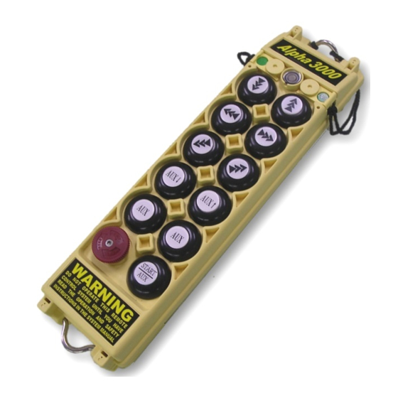
Page 4: Transmitter Illustration
START (Transmitter Front View) (Transmitter Back View) Pushbutton #1 (U or ↑) Transmitter Unit 10. Pushbutton #3 (E or →) Status LED Display* 11. Pushbutton #5 (N or ↗) Spare Power Key Pushbutton #2 (D or ↓) 12. Pushbutton #7 (START/AUX) Pushbutton #4 (W or ←) 13. -
Page 5: Alpha 3000F Models Internal Assembly
(PCB Front View) (PCB Back View) RF module Power ON/OFF Micro-Switch Status LED Display Battery Power Connector 1, 2 or 3-Step Pushbuttons RF test pin Emergency Stop Button (EMS) ID Code Soldering Slot (1 digit) Internal Antenna 10. Channel Dip-switch 11. -
Page 6: Alpha 3000D Models External Assembly
(Transmitter Front View) (Transmitter Back View) 11. Pushbutton #1 (U or ↑) Transmitter Unit 12. Pushbutton #3 (E or →) Status LED Display* 13. Pushbutton #5 (N or ↗) Spare Power Key Pushbutton #2 (D or ↓) 14. Pushbutton #7 (AUX or AUX ↑) Pushbutton #4 (W or ←) 15. -
Page 7: Alpha 3000D Models Internal Assembly
(PCB Front View) (PCB Back View) 1. RF module Power ON/OFF Micro-Switch 2. Status LED Display Battery Power Connector 3. 1, 2 or 3-Step Pushbuttons RF test pin 4. Emergency Stop Button (EMS) Channel Dip-switch Slot (1 digit) 5. Internal Antenna 10. -
Page 8: Receiver Illustration
(Alpha 3000 Models Receiver External View) Antenna Seat External Grounding Hole Receiver Enclosure Rubber Shock Absorber Key Lock System Information Cable Gland/Cord Grip... -
Page 9: Alpha 3000F Models Internal Assembly
K10 K11 K12 (Alpha 3000F2 & F3 Models Receiver Internal View) Antenna Seat 9. Bottom Relay Board Receiving RF Module 10. Power Transformer Decoder Module 11. Input Voltage Selector Seat Decoder Module Power Display 12. Contact Relay LED Display Receiver Status LED Display* 13. -
Page 10: Alpha 3000D Models Internal Assembly
K3 K4 K7 K8 K11 K12 K17 K18 K19 K20 K22 K23 (Alpha 3000D2 & D3 Models Receiver Internal View) 1. Antenna Seat 9. Bottom Relay Board 2. Receiving RF Module 10. Power Transformer 3. Decoder Module 11. Input Voltage Selector Seat 4. -
Page 11: Output Contact Diagram
5. OUTPUT CONTACT DIAGRAM UPPER RELAY BOARD MAIN BOTTOM RELAY BOARD Note A: AUX output contact represents the 7 pushbutton on the transmitter (START/AUX), which can be used for lights, horn, or other types of applications (refer to section 6.6 on page 24). Note B: The preprinted output contact markings on the relay boards below the terminal blocks are intended for Alpha 3000F3 and Alpha 3000D3 models. -
Page 12: Alpha 3000F3 Output Contact
UPPER RELAY BOARD MAIN BOTTOM RELAY BOARD Note: AUX output contact represents the 7 pushbutton on the transmitter (START/AUX), which can be used for lights, horn, or other types of applications (refer to section 6.6 on page 24). Terminal Block and Common Shorting Pin Assembly Common shorting pin illustrated above can be used rather than “daisy chaining”... -
Page 13: Alpha 3000D2 Output Contact
UPPER RELAY BOARD MAIN BOTTOM RELAY BOARD Note A: AU & AD output contacts represent the 7 and 8 pushbuttons on the transmitter (AUX↑ & AUX↓), which can be used for the auxiliary hoist motion or other types of applications (refer to section 6.6 on page 24). -
Page 14: Alpha 3000D3 Output Contact
UPPER RELAY BOARD MAIN BOTTOM RELAY BOARD Note A: AU & AD output contacts represent the 7 and 8 pushbuttons on the transmitter (AUX↑ & AUX↓), which can be used for the auxiliary hoist motion or other types of applications (refer to section 6.6 on page 24). - Page 15 There are numerous functions that can be set via jumpers located inside the decoder module. Please see the diagram and chart below on how to set these functions. JUMP Manufacture Setting for Alpha 3000F2 & D2 Models * Insert the transmitter power key will activate the receiver MAIN. Open * Reset the red EMS button will activate the receiver MAIN (refer to note A).
- Page 16 → “1” Top Location Bottom Location → “0” Manufacture Setting for Alpha 3000D2 Model Both 1 and 2 speed contact relays energized (closed) when either #7or #8 transmitter “0” pushbutton (AUX ↑ or AUX ↓) is pressed to the 2 speed.
- Page 17 JP1 (For all models) Insert the transmitter Press and hold Receiver MAIN After EMS Press and hold Receiver MAIN Open power key START/AUX activated reset START/AUX activated Insert the transmitter Receiver MAIN Re-insert the transmitter OR After EMS reset Receiver MAIN activated Short power key activated...
-
Page 18: Security Id Code Settings
Soldered ----- ' I ' Value Due to Alpha 3000 series’ ID code (or address code) is 16-digit long, the first 8 digits are set via the soldering slot and the remaining last 8 digits are set via the dip-switch (total of 16 digits). For the soldering slot, the “SH8”... -
Page 19: Frequency (Rf) Channel Settings
Example 1: ID code 00000000:10101010 Example 2: ID code 01011001:00011100 All Alpha 3000 systems are also equipped with a PLL synthesized receiving RF module with up to 63 user-adjustable RF channels. The RF channel dip-switch is located on the topside of the receiving RF module, covered by a sliding door. -
Page 20: How To Change The Transmitter Channels
For example: Change from channel 201(301.105MHz) to 202(301.130MHz). 1. Pull out the power key. 2. Unscrew and disassemble the transmitter bottom casing then you will see the encoder board as below Fig. 1. (Fig.1) 3. Take out one of the batteries. 4. - Page 21 (Fig.2) 5. Change the DIP3 to channel 202 (frequency dip-switch 00000010) as shown on Fig.3. (Fig.3) 6. Change “1” of the DIP3 to “ON” position as shown on Fig.4 to setting status (frequency dip-switch 10000010). (Fig.4) 7. Put the battery back into the battery compartment and insert the power key to its original position, then green LED is ON and the change is completed.
- Page 22 Number 1 is set as Number 2-8 is the the write-in binary channel selecting dip-switch. “ON” is dip-switch. “ON” is “1” and “OFF” is “0”. the setting status. As shown above, the dip-switch setting is 10000010 for channel 202.
-
Page 23: Frequency (Rf) Channel Table
Dip-Switch Setting Band 301MHz Dip-Switch Setting Channel Band 301MHz Channel Transmitter Receiver Transmitter Receiver 00001 00000001 000001 100001 301.1050 MHz 301.9050 MHz 00010 00000010 000010 100010 301.1300 MHz 301.9300 MHz 00000011 000011 301.9550 MHz 00011 100011 301.1550 MHz 00000100 000100 301.9800 MHz 00100 100100... -
Page 24: Pushbutton Contact Settings
For example: Change the frequency band from 433MHz to 480MHz. 1. Pull out the power key. 2. Unscrew and disassemble the transmitter bottom casing from the transmitter and you will see the encoder board. 3. Take out the batteries. 4. The below Fig.5 shows the SH number of each frequency band needs to be shorted. (Fig.5) Unsolder the SH37 to make it open and then short the SH38 for band 480MHz. -
Page 25: Voltage Settings
For example: Change the transmitting power from 0dBm to -3dBm. 1. Pull out the power key. 2. Unscrew and disassemble the transmitter bottom casing from the transmitter and you will see the encoder board. 3. Take out the batteries. 4. The below Fig.8 shows the SH number of the transmitting power needs to be shorted. (Fig.8) Unsolder the SH33 to make it open and then short the SH34 for -3dBm. - Page 26 There are numerous pushbutton functions that can be programmed via an 8-position dip-switch located on the decoder module (refer to the diagram below). By adjusting each dip setting either to the top or bottom location will change the contact form of the intended pushbutton (refer to the chart below). Transmitter pushbuttons are numbered from right-to-left and then from top-to-bottom.
- Page 27 There are four different voltage settings available inside the Alpha 3000 receiver located next to the bottom relay board, please select one that corresponds to the main power source of the crane or equipment. Power Transform Available: → SSB-2181 48VAC / 220VAC / 0ACV / 460VAC @ 50/60Hz. →...
-
Page 28: Receiver Installation
Required Tools: Flat Head Screwdriver (-) Phillips Head Screwdriver (+) Multi-Meter Open End Wrench Power Drill with 10.5mm ~ 11mm Drill-Bit Check to ensure that your receiver is not set to the same RF channel and ID code as any other systems in operation at the same facility or within distance of 300 meters. -
Page 29: System Testing
Connect the power source to the receiver and test the MAIN relay output (red EMS button) and observe that it properly opens and closes the main line. Test the operation of each function to ensure it corresponds to the transmitter direction labels and/or the pendant it is replacing. -
Page 30: Transmitter Operation
Batteries _ Make sure the four “AA” alkaline batteries are installed correctly, the labels on the battery holder will tell you which side is “up” and which side is “down”. Use 2,000mA alkaline type batteries for optimum operating time between replacements. If rechargeable batteries are used, for optimum operating time between replacements, select ones rated above 1,600mA. - Page 31 remove the JP2 jumper (refer to JP2 setting on page 15 & 16) then the MAIN relay will remain closed until the “Stop” command is received or the main power source to the crane or equipment is turned off. EMS & Restarting _ In case of an emergency, press down the red EMS button will immediately deactivate the transmitter power and receiver MAIN relay.
-
Page 32: Trouble Shooting
Should the operator find the equipment not operating normally, please check the chart below for simple trouble shooting tips. PROBLEM POSSIBLE REASON SOLUTION Ensure the correct transmitter is in Transmitter does not Transmitter and the receiver are use. The labels on the receiver and communicate to not on the same RF channel the transmitter will identify the RF... -
Page 33: System Specification
Transmitter Unit Frequency Range 301 MHz Transmitting Range 100 meters ≧6 Hamming Distance Channel Spacing 25KHz Frequency Control Synthesizer (PLL) Frequency Drift < 5ppm @ -25℃ ~ +75℃ Frequency Deviation < 1ppm @ 25℃ Spurious Emission -50dB Transmitting Power ~10.0mW Emission Antenna Impedance 50 ohms... -
Page 34: Parts List
Encoder Board (Alpha 3000F2 Model) EN-3000F2 Encoder Board (Alpha 3000F3 Model) EN-3000F3 Encoder Board (Alpha 3000D2 Model) EN-3000D2 Encoder Board (Alpha 3000D3 Model) EN-3000D3 301 MHz Receiving RF Module (All Models) RX-3000 Decoder Module (All Models) DE-3000 Upper Rely Board (Alpha 3000F2 Model) RY-3000F2 Upper Rely Board (Alpha 3000F3 Model) RY-3000F3...
Need help?
Do you have a question about the Alpha 3000 Series and is the answer not in the manual?
Questions and answers
Transmitter not communicating with the receiver