Table of Contents
Advertisement
Quick Links
EVCO S.p.A. | Code 104RS235E104 | Page 1 of 10 | PT 07/14 | version 1.0
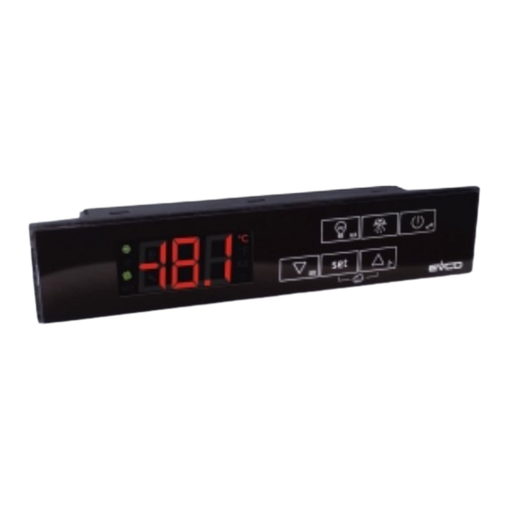
EVRS225 & EVRS235
Controllers in split version for refrigerated display cases, counters in butcher's shop and sweet counters
EN
ENGLISH
DIMENSIONS AND INSTALLATION
User interface dimensions and installation
The dimensions are expressed in mm (in); panel installation is envisioned, with elastic retainer wings (det. A).
For the dimensions and installation of the control module, see page 10.
28.0
(1.102)
detail A
1
2
To facilitate removal f the user interface, slightly smooth the internal longitudinal edges of the drilling template before
installation (det. B and C).
detail B
detail C
ELECTRIC CONNECTION
Electric connection
EVRS225 & EVRS235
User interface
21
22
23
24
25
EVRS225 & EVRS235
Control module
21 22 23 24
180,0 (7,086)
drilling template
138,0 (5,433)
detail B
detail C
P4 = 1, 2 o 3
PWM output
port for
remote
indicator
(on request)
26
27
28
29
30
31
32
33
34
35 36 37
MODBUS TTL port
K3
K2
K4
K1
K5
max. 20 A
13
14
15
16
17
3
4
5
6
7
29,0 (1,141)
third input
P4 = 0
25
26
27
28
29
30
31
phase
20
neutral
19
power supply
earth
18
8 9
IMPORTANT
Read this document thoroughly before installation and be-
fore use of the device and follow all recommendations;
keep this document with the device for future consultation.
Only use the device in the way described in this document;
do not use the same as a safety device.
The device must be disposed of in compliance with
local standards regarding the collection of electric
and electronic equipment.
1
DIMENSIONS AND INSTALLATION
1.1
Installation warnings
-
the thickness of the panel on which the user interface is
to
be
installed
2.0 mm (0.031 and 0.078 in)
-
make sure that the device work conditions (tempera-
ture of use, humidity, etc.) lie within the limits indi-
cated; see chapter 13
-
do not install the device near to any heat sources (heating
elements, hot air ducts etc.), equipment containing
powerful magnets (large diffusers, etc.), areas affected
by direct sunlight, rain, humidity, excessive dust, me-
chanical vibrations or shocks.
-
any metal parts in proximity of the control module must
be at a distance such that they do not compromise the
safety distances.
-
in compliance with Safety Standards, the device must
be installed correctly and in a way to protect against
any contact with electric parts; all parts that ensure
protection must be fixed in a way that they cannot be
removed without the use of tools.
2
ELECTRIC CONNECTION
2.1
Warnings for the electric connection
-
do not use electric or pneumatic screwdrivers on the
device terminal board
-
if the device has been taken from a cold to hot place,
humidity could condense inside; wait about 1 hour be-
fore powering it
-
make sure that the power supply voltage, the fre-
quency and the operational electric power of the de-
vice, correspond with those of the local power supply;
see chapter 13
-
disconnect the device power supply before proceeding
with any type of maintenance
-
position the power cables as far away as possible from
the signal cables
-
for repairs and information regarding the device, con-
tact the EVCO sales network.
3
USER INTERFACE
3.1
Preliminary notes
Operating Statuses:
-
"on" state (the device is powered and is on: the regu-
lators can be switched on)
-
"stand-by" status (the device is powered but is switched
off via software: the regulators are switched off; the
possibility to manually switch on/switch off the cabinet
light or auxiliary output depends on parameter u2)
-
the "off" status (the device is not powered).
Hereafter, with the word "start-up" means the passage from
"stand-by" status to "on" status; the word "shutdown" means
the passage from "on" status to "stand-by" status.
When the power is switched back on, the device displays the
port for
status that it was in at the time it was disconnected.
remote
indicator
3.2
Device switch-on/off in manual mode
(on request)
Operating Statuses:
32
33
34
1.
Make sure that the keyboard is not locked and that no
procedure is in progress.
2.
Hold the
key down for 2 s: the
off/on.
Using the digital inputs it is also possible to remotely switch
on/off the device.
3.3
The display
If the device is switched on, during normal operation, the
display will show the magnitude established with P5, except
during defrosting, when the device will show the tempera-
ture established with parameter d6.
If the device is switched off, the display will be switched off.
3.4
Cabinet temperature display (if parameter P4
is set at 0, 1 or 2) or the temperature de-
tected by the inlet air probe (if parameter P4
is set at 3)
1.
Make sure that the keyboard is not locked and that no
procedure is in progress.
2.
Hold the
key down for 1 s: the display will show the
first label available.
3.
Press and release the
"Pb1".
must
be
between
0.8
and
LED will switch
key or the
key to select
Advertisement
Table of Contents

Subscribe to Our Youtube Channel
Related Manuals for Evco EVRS225


Summary of Contents for Evco EVRS225
- Page 1 EVCO S.p.A. | Code 104RS235E104 | Page 1 of 10 | PT 07/14 | version 1.0 EVRS225 & EVRS235 Controllers in split version for refrigerated display cases, counters in butcher’s shop and sweet counters ENGLISH IMPORTANT Read this document thoroughly before installation and be- fore use of the device and follow all recommendations;...
-
Page 2: Energy Saving
EVCO S.p.A. | Code 104RS235E104 | Page 2 of 10 | PT 07/14 | version 1.0 Press and release the key. 3.10 Switch-on/off of the cabinet light in manual MULTIDECK To exit the procedure: mode (only if parameter u1 and/or param-... -
Page 3: Compressor Operating Hours Count
EVCO S.p.A. | Code 104RS235E104 | Page 3 of 10 | PT 07/14 | version 1.0 To select an alarm: If the digital input is connected in parallel to the digital input of Setting the configuration parameters Press and release the key or the key. - Page 4 EVCO S.p.A. | Code 104RS235E104 | Page 4 of 10 | PT 07/14 | version 1.0 the auxiliary output will have been switched Power supply cut-off alarm (HACCP). check the device-probe connection on in manual mode (only if parameter u1...
-
Page 5: Technical Data
EVCO S.p.A. | Code 104RS235E104 | Page 5 of 10 | PT 07/14 | version 1.0 TECHNICAL DATA 1 x 16 A res. output @ 250 VAC type SPST (K4) for 13.1 Technical data management of the cabinet light, demisting heating Purpose of the command device: operating command elements, aux. - Page 6 EVCO S.p.A. | Code 104RS235E104 | Page 6 of 10 | PT 07/14 | version 1.0 WORKING SETPOINT AND CONFIGURATION PARAMETERS 14.1 Working set-point PARAM. MIN. MAX. U.M. EVRS225 EVRS235 WORKING SETPOINT °C/°F (1) -18,0 -18,0 working set-point; see also r0 14.2...
- Page 7 EVCO S.p.A. | Code 104RS235E104 | Page 7 of 10 | PT 07/14 | version 1.0 - - - defrosting when device is switched on (only if d8 = 0, 1, 2 or 3) (4) if d4 = 0, minimum time between switching on of device and activation of defrosting; see also i0 and i5 (4) if d4 = 1, delay in activation of defrosting after device is switched on ;...
- Page 8 EVCO S.p.A. | Code 104RS235E104 | Page 8 of 10 | PT 07/14 | version 1.0 delay in the switching off of condenser fan following the switching off of the compressor (only if P4 = 0, 2 or 3and u1 and/or u11= 10 s duration of evaporator fan switch off during “energy saving”...
- Page 9 EVCO S.p.A. | Code 104RS235E104 | Page 9 of 10 | PT 07/14 | version 1.0 time that must pass in absence of door micro switch input activations (after the cabinet temperature or the CPT temperature has reached the work set point) for the “energy saving” function to be activated; see also r4, H01... H14...
-
Page 10: Dimensions And Installation
The dimensions are expressed in mm (in); installation is envisioned on a flat surface, with shims. EVCO S.p.A. This document is exclusive property of EVCO. EVCO does not assume any liability regarding possible errors stated. Via Feltre 81, 32036 Sedico (BL) ITALY The customer (manufacturer, installer or final user) assumes all liability regarding configuration of the device.
Need help?
Do you have a question about the EVRS225 and is the answer not in the manual?
Questions and answers