Table of Contents
Advertisement
Quick Links
Advertisement
Table of Contents

Related Manuals for Evco EVFTFT219


Summary of Contents for Evco EVFTFT219
- Page 1 EVCO S.p.A. EVFTFT219 | Installation guide ver. 1.0 | Code 144FTFT219E104 EVFTFT219 Controller laboratory refrigerated cabinets, in split version and which can be integrated into the unit Installation guide | ENGLISH Code 144FTFT219E104 pagina 1 di 50...
- Page 2 EVCO S.p.A. EVFTFT219 | Installation guide ver. 1.0 | Code 144FTFT219E104 Important Read this document thoroughly before installation and before use of the device and follow all recommendations; keep this document with the device for future consultation. Only use the device in the way described in this document; do not use the same as a safety device.
-
Page 3: Table Of Contents
EVCO S.p.A. EVFTFT219 | Installation guide ver. 1.0 | Code 144FTFT219E104 Indice INTRODUCTION ..........4 Introduction ............ 4 Technical features ..........5 DESCRIPTION ..........7 User interface ..........7 Control module ..........9 DIMENSIONS AND INSTALLATION ....10 User interface dimensions ....... 10 Control module dimensions ...... -
Page 4: Introduction
EVCO S.p.A. EVFTFT219 | Installation guide ver. 1.0 | Code 144FTFT219E104 INTRODUCTION Introduction EVFTFT219 is a controller with elegant design for the management of laboratory refrigerated cabinets. It is available in split version and can be mechanically and aesthetically integrated into the unit; the user interface consists of a colour TFT graphic display, touch keys and guarantees an IP65 protection rating, for easy cleaning. -
Page 5: Technical Features
EVCO S.p.A. EVFTFT219 | Installation guide ver. 1.0 | Code 144FTFT219E104 Technical features EVFTFT219Z9U Power supply • 115... 230 VAC Analogue inputs cabinet probe (2 wires Pt 1000) • evaporator probe (2 wires Pt 1000) • condenser probe (2 wires Pt 1000) •... - Page 6 EVCO S.p.A. EVFTFT219 | Installation guide ver. 1.0 | Code 144FTFT219E104 • clock • alarm buzzer access to the functions through user identification, tracking of the activities and consequent recording of • the temperature values power failure management strategies •...
-
Page 7: Description
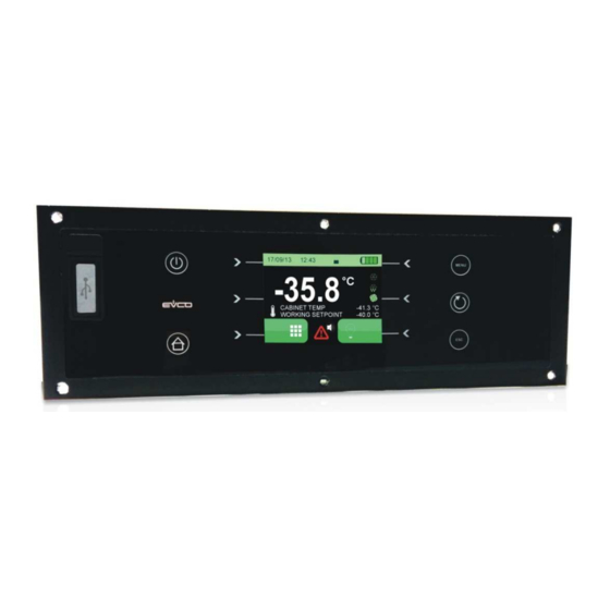
EVCO S.p.A. EVFTFT219 | Installation guide ver. 1.0 | Code 144FTFT219E104 DESCRIPTION User interface The following drawing shows the layout of the user interface. The following table describes the meaning of the parts of the device user interface. PART MEANING escape key, hereinafter also “ESCAPE”... - Page 8 EVCO S.p.A. EVFTFT219 | Installation guide ver. 1.0 | Code 144FTFT219E104 USB port control module communication port and RS-485 MODBUS port functional earth RS-485 MODBUS port termination resistor product probe, backup battery status and power supply status analogue inputs For additional information, please refer to the following chapters.
-
Page 9: Control Module
EVCO S.p.A. EVFTFT219 | Installation guide ver. 1.0 | Code 144FTFT219E104 Control module The following drawing shows the layout of the control module. The following table shows the meaning of the parts of the device control module. PART MEANING power supply... -
Page 10: Dimensions And Installation
EVCO S.p.A. EVFTFT219 | Installation guide ver. 1.0 | Code 144FTFT219E104 DIMENSIONS AND INSTALLATION User interface dimensions The following drawing shows the measures of the user interface, in mm (in). Control module dimensions The following drawing shows the measures of the control module, in mm (in). -
Page 11: User Interface Installation
EVCO S.p.A. EVFTFT219 | Installation guide ver. 1.0 | Code 144FTFT219E104 User interface installation The following drawing explains how to install the user interface. Installation is by back-panel, with threaded studs and guarantees flush mounting. Control module installation The control module is to be installed on a flat surface, with spacers. -
Page 12: Wiring
EVCO S.p.A. EVFTFT219 | Installation guide ver. 1.0 | Code 144FTFT219E104 WIRING The following diagram shows the wiring connections of the device. Warnings for the wiring do not use electric or pneumatic screwdrivers on the device terminal board if the device has been taken from a cold to hot place, humidity could condense inside; wait about 1 hour before powering it make sure that the power supply voltage, the frequency and the operational electric power of the device correspond with those of the local power supply;... - Page 13 EVCO S.p.A. EVFTFT219 | Installation guide ver. 1.0 | Code 144FTFT219E104 for repair and information regarding the device, contact the EVCO sales network. pagina 13 di 50...
-
Page 14: Device Usage
EVCO S.p.A. EVFTFT219 | Installation guide ver. 1.0 | Code 144FTFT219E104 DEVICE USAGE First usage Operate as follows: Install the device as described in chapter 3 DIMENSIONS AND INSTALLA “ ”, following all Errore. instructions listed under paragraph 3.5 ”... -
Page 15: User Interface
EVCO S.p.A. EVFTFT219 | Installation guide Installation guide ver. 1.0 | Code 144FTFT219E104 USER INTERFACE Preliminary notes With “functioning mode”, we refer to the following modes: With “functioning mode”, we refer to the following modes: “on” mode (the device is powered and is on: the is powered and is on: the regulators can be switched on). -
Page 16: Battery Status
If that does not resolve the issue, contact the EVCO contact the EVCO sales network. Keypad lock/unlock The keypad lock is enabled by parameter D08. -
Page 17: User Identification Function
EVCO S.p.A. EVFTFT219 | Installation guide ver. 1.0 | Code 144FTFT219E104 For the user identification procedure, refer to paragraph USER IDENTIFICATION 9.2.6.5 FUNCTION User identification function BACKUP BATTERY The “user identification” function can be enabled/disabled by Battery functioning during a parameter ID. -
Page 18: Settings
EVCO S.p.A. EVFTFT219 | Installation guide ver. 1.0 | Code 144FTFT219E104 SETTINGS Preliminary notes To access the menu functions on the display, operate as shown in the paragraphs below. The following is a list of the main selection keys: key HOME: it allows to display the main screen... - Page 19 EVCO S.p.A. EVFTFT219 | Installation guide ver. 1.0 | Code 144FTFT219E104 9.2.2 Start up of a defrosting cycle Press the key to start up a manual defrosting cycle: Note : if parameter S01 is not properly configured, no defrosting cycle is allowed when pressing this key.
- Page 20 EVCO S.p.A. EVFTFT219 | Installation guide ver. 1.0 | Code 144FTFT219E104 When restoring the session after the device has been shut down due to low battery, the following screen is displayed. Press the key OK to recover the normal operations.
- Page 21 EVCO S.p.A. EVFTFT219 | Installation guide ver. 1.0 | Code 144FTFT219E104 9.2.4.1 Alarm list Press the key to access the alarms display mode. It is possible to record up to 30 alarms with related information. When recorded, the display shows the information related to the latest ↑...
- Page 22 EVCO S.p.A. EVFTFT219 | Installation guide ver. 1.0 | Code 144FTFT219E104 It is possible to edit the graph by using the following keys: Y+ e Y- : to change the scale of the ordinate axis (Y zooming) X+ e X- : to shift the scale along the abscissa axis IN e OUT : to change the scale of the abscissa axis (X zooming) On the abscissa axis, the time is expressed in minutes up to 600 minutes, beyond this limit it is expressed in hours.
- Page 23 EVCO S.p.A. EVFTFT219 | Installation guide ver. 1.0 | Code 144FTFT219E104 9.2.4.4 Door opening time Press the key to display the door opening record of the current day. Records of other days may be viewed by scrolling with the arrow keys.
- Page 24 EVCO S.p.A. EVFTFT219 | Installation guide ver. 1.0 | Code 144FTFT219E104 started manually from keypad. started one hour after the refrigerator switch-on. started by time intervals based on refrigeration working times. started by time intervals based on compressor working time.
- Page 25 EVCO S.p.A. EVFTFT219 | Installation guide ver. 1.0 | Code 144FTFT219E104 To download the data recorded on the device and to download/upload setup parameters, turn off the device and insert a USB key into the keypad USB port. The following screen will be displayed.
- Page 26 EVCO S.p.A. EVFTFT219 | Installation guide ver. 1.0 | Code 144FTFT219E104 9.2.6 “SERVICE” menu Press the key to access the sub-menu “service” consisting of the following functions/screens: 9.2.6.1 Date and time setup Press the key to enter the clock edit mode: the arrow keys allow to select the desired field of the clock, while the keys + e –allow to modify the values;...
- Page 27 EVCO S.p.A. EVFTFT219 | Installation guide ver. 1.0 | Code 144FTFT219E104 9.2.6.3 Probe readings Press the key to display the values detected by the probes. 9.2.6.4 Cabinet and product probe calibration This function allows to calibrate the cabinet and product probe according to the machine specific range of temperatures.
- Page 28 EVCO S.p.A. EVFTFT219 | Installation guide ver. 1.0 | Code 144FTFT219E104 Press the keys + e – to set the proper value and press the key SET to start up the machine with the new setpoint value. The following screen will be displayed: The real temperature is displayed on the left, while the calibration temperature is displayed in green on the right.
- Page 29 EVCO S.p.A. EVFTFT219 | Installation guide ver. 1.0 | Code 144FTFT219E104 After a few seconds, a summary screen disclosing the calibration values and the current probe temperature will be displayed: During calibration, it is not possible to go back and recalibrate a point whose value has been already set. Should a new calibration be required, the procedure must be re-performed from the beginning by pressing ESC and going back to the desired probe selection screen.
- Page 30 EVCO S.p.A. EVFTFT219 | Installation guide ver. 1.0 | Code 144FTFT219E104 9.2.6.5 User identification setting Press the key to enter the screen allowing the setting/activation of the 6 USER IDs who will have access to functions requiring login credentials. Only user 1 is entitled to define and modify all other users login credentials (refer to paragraph Errore.
- Page 31 EVCO S.p.A. EVFTFT219 | Installation guide ver. 1.0 | Code 144FTFT219E104 The parameters list may be scrolled by means of the arrow keys, while the keys + e – will modify the values. The newly set value is automatically saved by moving to the next or previous parameter.
-
Page 32: List Of Configuration Parameters
EVCO S.p.A. EVFTFT219 | Installation guide ver. 1.0 | Code 144FTFT219E104 List of configuration parameters La seguente tabella illustra il significato dei parametri di configurazione dei dispositivi. PARAM. DEFAULT MIN. MAX. M.U. ALARMS °C/°F low cabinet temperature alarm offset (related to the setpoint) °C/°F... - Page 33 EVCO S.p.A. EVFTFT219 | Installation guide ver. 1.0 | Code 144FTFT219E104 Keypad lock not enabled - - - - lock/unlock enabled by key lock enabled by timeout or key, unlock enabled by key °C/°F cabinet probe offset °C/°F evaporator probe offset °C/°F...
- Page 34 EVCO S.p.A. EVFTFT219 | Installation guide ver. 1.0 | Code 144FTFT219E104 time span between two defrosting cycles defrosting types VIA STOPPING OF COMPRESSOR - during defrosting, the compressor will remain off and the defrosting output will remain deactivated ELECTRIC - during defrosting, the compressor will remain off...
- Page 35 EVCO S.p.A. EVFTFT219 | Installation guide ver. 1.0 | Code 144FTFT219E104 evaporator fans control enabled depending on evaporator temperature: the fans are activated depending on F03 during normal operation and depending on F07 following a defrosting or a device switch-on...
- Page 36 EVCO S.p.A. EVFTFT219 | Installation guide ver. 1.0 | Code 144FTFT219E104 PARAM. DEFAULT MIN. MAX. M.U. FANS evaporator fans disabled - - - - enabled refer also to parameter C09 condenser fans disabled - - - - enabled refer also to parameter C08 evaporator fans setpoint during normal operation ≤...
- Page 37 EVCO S.p.A. EVFTFT219 | Installation guide ver. 1.0 | Code 144FTFT219E104 energy saving end time 24h = disabled °C/°F setpoint increase under energy saving PARAM. DEFAULT MIN. MAX. U.M. SAMPLING sampling time - - - - disabled enabled PARAM. DEFAULT MIN.
- Page 38 EVCO S.p.A. EVFTFT219 | Installation guide ver. 1.0 | Code 144FTFT219E104 main view on display AUX10 - - - - cabinet probe product probe - - - - display contrast user identification code - - - - deactivated activated Notes: the unit of measurement is given by parameter D01.
-
Page 39: Signals
EVCO S.p.A. EVFTFT219 | Installation guide ver. 1.0 | Code 144FTFT219E104 SIGNALS 10.1 Signals The following table describes the device signal ICONS. ICON MEANING compressor ICON If on: the compressor is on defrosting ICON If on: a defrosting is in progress... -
Page 40: Alarms
EVCO S.p.A. EVFTFT219 | Installation guide ver. 1.0 | Code 144FTFT219E104 ALARMS 11.1 Alarms The pre-alarm warnings are displayed in green, while the alarm warnings are displayed in red. The pre-alarm warnings depend on parameter D05 and are provided only for the open–door alarm and high and low cabinet temperature alarms. - Page 41 EVCO S.p.A. EVFTFT219 | Installation guide ver. 1.0 | Code 144FTFT219E104 low cabinet temperature alarm if cabinet T° < setpoint+A01 → pre-alarm (only if D05=1) if cabinet T° < setpoint when A03 and A04 delay time has elapsed→ alarm corrective measures:...
- Page 42 EVCO S.p.A. EVFTFT219 | Installation guide ver. 1.0 | Code 144FTFT219E104 condenser high temperature alarm if condenser T° > A06 corrective measures: the same as above main consequences: Condens. High T° the alarm is memorized while the adaptive defrosting data are deleted...
- Page 43 EVCO S.p.A. EVFTFT219 | Installation guide ver. 1.0 | Code 144FTFT219E104 low product temperature alarm if product T° < setpoint + AUX2 when AUX9 andAUX8 delay time has elapsed corrective measures: Low Product T° the same as above ALARM main consequences:...
-
Page 44: Accessories
EVCO S.p.A. EVFTFT219 | Installation guide ver. 1.0 | Code 144FTFT219E104 ACCESSORIES 12.1 Backup module EVC99P00X7XXX00 12.1.1 Preliminary notes The module guarantees, for as long as a backup battery lasts, power to the user interface and the recording of the temperature value measured by a product probe in the event of a power failure to the controller. -
Page 45: Technical Data
EVCO S.p.A. EVFTFT219 | Installation guide ver. 1.0 | Code 144FTFT219E104 TECHNICAL DATA 13.1 Technical data Purpose of the command device: operating command device Construction of the command device: built-in electronic device user interface: open frame board on methacrylate plate... - Page 46 EVCO S.p.A. EVFTFT219 | Installation guide ver. 1.0 | Code 144FTFT219E104 user interface: supplied by the control module Power supply: control module: 115... (±15%), (±3 Hz), 10 VA max. Rated impulse voltage: 4 KV. Overvoltage category: III. Class and structure of software: embedded (with supercap battery).
- Page 47 EVCO S.p.A. EVFTFT219 | Installation guide ver. 1.0 | Code 144FTFT219E104 Signal buzzer and alarm: embedded pagina 47 di 50...
- Page 48 EVCO S.p.A. EVFTFT219 | Installation guide ver. 1.0 | Code 144FTFT219E104 pagina 48 di 50...
- Page 49 EVCO S.p.A. EVFTFT219 | Installation guide ver. 1.0 | Code 144FTFT219E104 EVFTFT219 Controller for laboratory refrigerated cabinets, in split version and which can be integrated into the unit Installation guide ver. 1.0 GA - 07/15 Code 144FTFT219E104 This document is exclusive property of EVCO; EVCO does not assume any liability regarding possible errors stated.
- Page 50 EVCO S.p.A. EVFTFT219 | Installation guide ver. 1.0 | Code 144FTFT219E104 EVCO S.p.A. Via Feltre 81, 32036 Sedico Belluno ITALIA Tel. 0437/8422 | Fax 0437/83648 info@evco.it | www.evco.it pagina 50 di 50...
Need help?
Do you have a question about the EVFTFT219 and is the answer not in the manual?
Questions and answers