Table of Contents
Advertisement
Quick Links
Advertisement
Table of Contents

Subscribe to Our Youtube Channel
Related Manuals for Evco EVFTFT618


Summary of Contents for Evco EVFTFT618
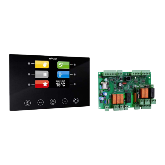
- Page 1 EVCO S.p.A. EVFTFT618 | Installer manual ver. 2.2 | Code 144FTFT618E224 EVFTFT618 Split execution controller for management of retarder-proofer cabinets/cells with capacitive type user interface and TFT graphic display ENGLISH INSTALLER MANUAL ver. 2.2 CODE 144FTFT618E224 Page...
- Page 2 EVCO S.p.A. EVFTFT618 | Installer manual ver. 2.2 | Code 144FTFT618E224 Important Important Read this document thoroughly before installation and before use of the device and follow all recommendations; keep this document with the device for future consultation. The following symbols support reading of the document: indicates a suggestion indicates a warning.
-
Page 3: Table Of Contents
EVCO S.p.A. EVFTFT618 | Installer manual ver. 2.2 | Code 144FTFT618E224 Index INTRODUCTION ........................... 5 Introduction ............................5 Summary table of the main features and the models available ..............6 DESCRIPTION ............................8 Description of the user interface ......................8 Description of the control module ...................... - Page 4 EVCO S.p.A. EVFTFT618 | Installer manual ver. 2.2 | Code 144FTFT618E224 9.3.2 Dehumidification management ..................... 31 Loads management ..........................31 10.1 Management of the compressor ....................... 31 10.2 Pump-down management ........................ 31 10.3 Management of the evaporator fan ....................32 10.4...
-
Page 5: Introduction
EVFTFT618 | Installer manual ver. 2.2 | Code 144FTFT618E224 1 INTRODUCTION Introduction EVFTFT618 is a digital controller studied to manage retarder proofer cabinets/cells, which can be mechanically and aesthetically integrated into the unit. The controller is fitted with: clock, signal buzzer and alarm... -
Page 6: Summary Table Of The Main Features And The Models Available
EVCO S.p.A. EVFTFT618 | Installer manual ver. 2.2 | Code 144FTFT618E224 Summary table of the main features and the models available The following table illustrates the main features of the device. “ / “ indicates the feature can be set via a configuration parameter. - Page 7 • restoring the factory settings • Notes: (1) The evaporator fan control signal can be analogue or digital. For further information, see chapter 0 15 TECHNICAL DATA; for other models contact the EVCO sales network. Page...
-
Page 8: Description
EVFTFT618 | Installer manual ver. 2.2 | Code 144FTFT618E224 2 DESCRIPTION Description of the user interface The following drawing illustrates the aspect of the EVFTFT618 user interface. The following table illustrates the meaning of EVFTFT618 user interface parts. Part Part on/off key, herein called also "ON/STAND-BY key"... -
Page 9: Description Of The Control Module
EVFTFT618 | Installer manual ver. 2.2 | Code 144FTFT618E224 Description of the control module The following drawing illustrates the aspect of the EVFTFT818 control module. The following table illustrates the meaning of EVFTFT618 control module parts. Part Part power supply... -
Page 10: Dimensions And Installation
EVCO S.p.A. EVFTFT618 | Installer manual ver. 2.2 | Code 144FTFT618E224 3 DIMENSIONS AND INSTALLATION User interface dimensions The following drawing illustrates the EVFTFT618 user interface dimensions; these are expressed in mm (in). partic. A partic. A Det. A Det. A partic. -
Page 11: User Interface Installation
EVCO S.p.A. EVFTFT618 | Installer manual ver. 2.2 | Code 144FTFT618E224 User interface installation Back panel via studs Control module installation On flat surface, with spacers. Installation warnings make sure that the device work conditions (temperature of use, humidity, etc.) lie within the limits indicated;... -
Page 12: Electric Connection
EVCO S.p.A. EVFTFT618 | Installer manual ver. 2.2 | Code 144FTFT618E224 4 ELECTRIC CONNECTION Electric connection The following drawing illustrates the EVFTFT618 electric connection. User interface USB port RS-485 port ground Power supply Evaporator fan at EVCFAN1 Control module mains... -
Page 13: Connection Of The Terminating Resistors Of The Communication Port
EVCO S.p.A. EVFTFT618 | Installer manual ver. 2.2 | Code 144FTFT618E224 4.1.1 Connection of the terminating resistors of the communication port The terminating resistor must be connected in order to reduce the reflections on the signal transmitted along the cables that connect the user interface to the control model. -
Page 14: Insertion Of The Rs-485 Serial Port Terminating Resistor
0 disconnect the device power supply before proceeding with any type of maintenance do not use this device as a safety device for repairs and information regarding the device, contact the EVCO sales network. Page... -
Page 15: User Interface
Operate as follows: 1. Connect the device power supply. if parameter E9 is set at 1, the device will display the EVCO splash screen for 10 seconds, otherwise it will display a black screen for 10 seconds, after which it will go to the STANDBY status. -
Page 16: Switching The Device On/Off
EVCO S.p.A. EVFTFT618 | Installer manual ver. 2.2 | Code 144FTFT618E224 2. Press and release the ON/STAND-BY (1) key. If the duration of power supply cut-off was such to cause the clock error, the board will display the clock setting screen directly. -
Page 17: Operation
EVCO S.p.A. EVFTFT618 | Installer manual ver. 2.2 | Code 144FTFT618E224 6. OPERATION Preliminary notes The controller supplies a complete control for retarder-proofer cabinets or cells for confectionery and bread-making, through the automatic management of the complete mixture retarder-proofer cycle. - Page 18 EVCO S.p.A. EVFTFT618 | Installer manual ver. 2.2 | Code 144FTFT618E224 PROVING phase The proving phase is the fourth phase of the automatic cycle. The temperature regulation is active and is NEUTRAL AREA, the work set-point is established by the final user. The passage from the recovery set-point (previous phase) to the proving set-point can be gradual with increase percentages established in the parameters programming phase.
-
Page 19: Pre-Selection Page
EVCO S.p.A. EVFTFT618 | Installer manual ver. 2.2 | Code 144FTFT618E224 6.1.1 Pre-selection page The Pre-selection page represents the "start point" foe navigating the user interface. The functions enabled and the dates data, time and temperature in cabinet are present in the pre-selection page. -
Page 20: Setting And Execution Of A Manual Cycle
EVCO S.p.A. EVFTFT618 | Installer manual ver. 2.2 | Code 144FTFT618E224 6.1.2 Setting and execution of a manual cycle Below the complete navigation system of the MANUAL menu is illustrated. From this menu it is possible to select and perform a complete manual COOLING or HEATING cycle. -
Page 21: Setting An Automatic Cycle
EVCO S.p.A. EVFTFT618 | Installer manual ver. 2.2 | Code 144FTFT618E224 6.1.3 Setting an automatic cycle Below the complete navigation system of the AUTOMATIC menu is illustrated. It is the real "heart" of the product as all retarder-proofer cycles will be set from this menu and the PROGRAMS and FAVOURITES menus will be passed on once the saved cycles have been selected. -
Page 22: Execution Of An Automatic Cycle
EVCO S.p.A. EVFTFT618 | Installer manual ver. 2.2 | Code 144FTFT618E224 6.1.4 Execution of an automatic cycle Below find the illustration of the complete navigation system during the execution of an automatic cycle. Once the automatic cycle is started, the following screen is displayed:... -
Page 23: The Programs Menu
EVCO S.p.A. EVFTFT618 | Installer manual ver. 2.2 | Code 144FTFT618E224 6.1.5 The PROGRAMS menu Below the complete navigation system of the PROGRAMS menu is illustrated. This menu allows to select the program to be performed and/or modified. Once selected, press the SET key. In this way the choice is confirmed and passes to the AUTOMATIC menu. -
Page 24: The Favourites Menu
EVCO S.p.A. EVFTFT618 | Installer manual ver. 2.2 | Code 144FTFT618E224 6.1.6 The FAVOURITES menu Below the complete navigation system of the FAVOURITES menu is illustrated. This menu has the purpose of quickly recalling the "favourites" cycles, i.e. the last 10 cycles performed by the machine. -
Page 25: The Pre-Cooling Menu
EVCO S.p.A. EVFTFT618 | Installer manual ver. 2.2 | Code 144FTFT618E224 6.1.7 The PRE-COOLING menu Below the complete navigation system of the PRE-COOLING menu is illustrated. This menu allows activate pre-cooling cabinet while waiting select retarder-proofer cycle. To reach the PRE-COOLING menu from the pre-selection page, press the key at the side of the PRE-COOLING icon:... -
Page 26: The Pre-Selection Page Options Menu
EVCO S.p.A. EVFTFT618 | Installer manual ver. 2.2 | Code 144FTFT618E224 6.1.8 The PRE-SELECTION PAGE OPTIONS menu Below the complete navigation system of the FAVOURITES menu is illustrated. To reach the PRE-SELECTION PAGE OPTIONS menu from the pre-selection page, press the MENU key. -
Page 27: The Service Menu
EVCO S.p.A. EVFTFT618 | Installer manual ver. 2.2 | Code 144FTFT618E224 6.1.8.1 The SERVICE menu Select the language using the UP and DOWN SETUP RECORDING allows to access a screen Press the SET key to confirm the value of the... -
Page 28: Detail Meaning Icons Status Regulators
EVCO S.p.A. EVFTFT618 | Installer manual ver. 2.2 | Code 144FTFT618E224 7 Detail Meaning Icons Status Regulators During the execution of a cycle (both manual and automatic) the states of the main utilities are displayed through the icons. White light on indicates the compressor is active... -
Page 29: Regulations
EVCO S.p.A. EVFTFT618 | Installer manual ver. 2.2 | Code 144FTFT618E224 9 Regulations Pre-cooling The pre-cooling cycle has the purpose of taking the cabinet to a determined temperature before selecting and performing a retarder-proofer cycle. During the pre-cooling cycle, the compressor, condenser fans, the pump-down electrovalve (if enabled) and the evaporator fan work to reach the temperature established. -
Page 30: Generating Heat
EVCO S.p.A. EVFTFT618 | Installer manual ver. 2.2 | Code 144FTFT618E224 9.2.2 Generating heat Generation of the heat refers to a heating element. During a heating request, the heating element outputs will be activated, with possibility of management of a switch-on and switch-off duty cycle, defined by parameters rH6 and rH7 in a way to limit the heating power if very powerful resistors are used, in order to prevent overheating in the cabinet. -
Page 31: Humidification Management
EVCO S.p.A. EVFTFT618 | Installer manual ver. 2.2 | Code 144FTFT618E224 9.3.1 Humidification management Generation of humidity refers to two different utilities, a humidity generator output and a humidifier output. The humidity generator output is activated during the phases in which management of humidification is envisioned; it is used for machines with external boiler, in order to generate the steam to be introduced successively into the cabinet whenever requested by the regulator. -
Page 32: Management Of The Evaporator Fan
EVCO S.p.A. EVFTFT618 | Installer manual ver. 2.2 | Code 144FTFT618E224 With pump-down managed from LP digital input (parameter u1 = 0 and i6 = 2): On activation of the compressor in parallel, the pump-down electrovalve will also be activated. -
Page 33: Management Of The Heating Elements
EVCO S.p.A. EVFTFT618 | Installer manual ver. 2.2 | Code 144FTFT618E224 10.5 Management of the heating elements During a heating request, the heating elements output will be activated, making the management of a switch-on/off duty- cycle also possible, defined by parameters rH6 and rH7. -
Page 34: Dehumidification Management
EVCO S.p.A. EVFTFT618 | Installer manual ver. 2.2 | Code 144FTFT618E224 10.8 Dehumidification management Dehumidification management is only active when the humidity management takes place via the use of the humidity transducer (rU0 = 0). The dehumidification can be managed in two different ways: via an extractor fan (parameter u3 = 0, utility associated to output K4) or via the activation of the cooling plant (compressor and pump-down electrovalve if present). -
Page 35: Alarms
EVCO S.p.A. EVFTFT618 | Installer manual ver. 2.2 | Code 144FTFT618E224 Alarms When an alarm occurs, a pop-up window opens a indicating the code of the alarm present. The buzzer sounds intermittently until any key is pressed that silences the buzzer and makes the pop-up window disappear. The alarm presence is indicated with the icon. - Page 36 EVCO S.p.A. EVFTFT618 | Installer manual ver. 2.2 | Code 144FTFT618E224 Power supply cut-off during execution of a cycle alarm Solutions: check the device-power supply connection Condenser overheated alarm. Solutions: check the temperature of the condenser check the value of the parameter C6.
- Page 37 EVCO S.p.A. EVFTFT618 | Installer manual ver. 2.2 | Code 144FTFT618E224 Humidity transducer error. Solutions: check the integrity of the transducer check the device-transducer connection check the humidity relative to the cabinet. Main consequences if parameter rU0 is set at 0: if the error occurs during “stand-by”, cycles that envision humidity management cannot be...
-
Page 38: Management Of The Host Usb Port On The Board
EVFTFT618 | Installer manual ver. 2.2 | Code 144FTFT618E224 Management of the Host USB port on the board The EVFTFT618 model mounts a USB port on the board able to perform the following functions: Allows the download of the data relative to the cycles performed onto USB (historic) -
Page 39: Parameters
EVCO S.p.A. EVFTFT618 | Installer manual ver. 2.2 | Code 144FTFT618E224 Parameters Par. Min. Max. Unit Default Analogue inputs °C offset cell probe °C offset evaporator probe °C offset condenser probe %r.H. humidity probe offset probe type - - - -... - Page 40 EVCO S.p.A. EVFTFT618 | Installer manual ver. 2.2 | Code 144FTFT618E224 °C cooling neutral area value for the baking delay phase °C pre-cooling set-point Par. Min. Max. Unit Default Heating regulator °C rH3, rH4, rH5 parameters differential minimum set-point that can be set for the recovery, °C...
- Page 41 EVCO S.p.A. EVFTFT618 | Installer manual ver. 2.2 | Code 144FTFT618E224 increase percentage 2nd proving step (with respect to 100%) increase percentage 3rd proving step (with respect to 100%) increase percentage 4th proving step (with respect to 100%) increase percentage 5th proving step (with respect to...
- Page 42 EVCO S.p.A. EVFTFT618 | Installer manual ver. 2.2 | Code 144FTFT618E224 0 = seconds 1 = minutes Par. Min. Max. Unit Default Compressor protection compressor switch-on delay from instrument switch-on minimum time between two compressor switch-ons (3) compressor switch off minimum duration...
- Page 43 EVCO S.p.A. EVFTFT618 | Installer manual ver. 2.2 | Code 144FTFT618E224 evaporator temperature above which evaporator high °C temperature alarm is activated (code “AH”); see also parameter A2 enabling of evaporator high temperature alarm (“AH” code) - - - - = yes Par.
- Page 44 EVCO S.p.A. EVFTFT618 | Installer manual ver. 2.2 | Code 144FTFT618E224 evaporator fan min speed calibration value evaporator fan max speed calibration value Par. Min. Max. Unit Default Digital inputs effect caused by opening the door, i.e. by activation of the...
- Page 45 EVCO S.p.A. EVFTFT618 | Installer manual ver. 2.2 | Code 144FTFT618E224 = normally closed (input active with open contact) input circuit breaker protection alarm signal delay (“CtH”code) -1 = the alarm will not be signalled Par. Min. Max. Unit Default...
- Page 46 EVCO S.p.A. EVFTFT618 | Installer manual ver. 2.2 | Code 144FTFT618E224 2 = automatic after 1 minute of inactivity during a cycle display of the EVCO splash screen on power supply restore - - - - 0 = black screen...
-
Page 47: Accessories
EVCO S.p.A. EVFTFT618 | Installer manual ver. 2.2 | Code 144FTFT618E224 Accessories 14.1 Phase speed regulator single phase fans EVDFAN1 14.1.1 Introduction EVDFAN1 is a phase cut speed regulator for single phase fans. The regulator control signal is the PWM type, the same supplied by the controller analogue output. -
Page 48: Dimensions
14.2 Synoptic Panel EVC25T00X7XXX04 This board reproduces the status of EVFTFT618. It is an optional board. Lack of the same does not generate any alarm signal. On system power on, the synoptic performs a lamp test with duration of 10 seconds. - Page 49 EVCO S.p.A. EVFTFT618 | Installer manual ver. 2.2 | Code 144FTFT618E224 At the end, it shows the OFF label on display DS1 if EVFTFT618 is in standby, or it shows the cabinet temperature and the current time on display DS6.
-
Page 50: Optoisolated Rs-485/Rs-232 Serial Interface Evif21Rs7I
EVCO S.p.A. EVFTFT618 | Installer manual ver. 2.2 | Code 144FTFT618E224 14.3 Optoisolated RS-485/RS-232 serial interface EVIF21RS7I 14.3.1 Introduction EVIF21RS7I is an optoisolated RS-485/RS-232 serial interface. The interface can be used to connect the controller to the Parameters Manager set-up software system. -
Page 51: Dimensions
EVCO S.p.A. EVFTFT618 | Installer manual ver. 2.2 | Code 144FTFT618E224 14.3.3 Dimensions The following drawing illustrates the EVIF21RS7I dimensions; these are expressed in mm (in). 14.3.4 Connection to the device Operate as follows: Cut the device power supply off. -
Page 52: Non-Isolated Rs-485/Usb Serial Interface Evif20Suxi
EVCO S.p.A. EVFTFT618 | Installer manual ver. 2.2 | Code 144FTFT618E224 14.4 Non-isolated RS-485/USB serial interface EVIF20SUXI 14.4.1 Introduction EVIF20SUXI is a non-isolated RS-485/USB serial interface. The interface can be used to connect the controller to the Parameters Manager set-up software system. -
Page 53: Dimensions
EVCO S.p.A. EVFTFT618 | Installer manual ver. 2.2 | Code 144FTFT618E224 14.4.3 Dimensions The following drawing illustrates the EVIF20SUXI dimensions; these are expressed in mm (in). 14.4.4 Connection to the device Operate as follows: Cut the device power supply off. -
Page 54: Technical Data
EVCO S.p.A. EVFTFT618 | Installer manual ver. 2.2 | Code 144FTFT618E224 TECHNICAL DATA 15.1 Technical data Purpose of the device: retarder proofer controller user interface control module Execution: board without cover behind board without cover. Plexiglas sheet. user interface control module Dimensions: 200.0 x 135.0 x 28.0 ±0.6 mm... - Page 55 EVCO S.p.A. EVFTFT618 | Installer manual ver. 2.2 | Code 144FTFT618E224 user interface control module Protection rating: IP65. IP00. user interface control module Connections: removable screw terminal board terminal board with extractable (control module and RS-485 serial screws (user interface, power port).
- Page 56 EVCO S.p.A. EVFTFT618 | Installer manual ver. 2.2 | Code 144FTFT618E224 normal. Pollution situation: user interface control module Power: 115/230 VAC (±15%), 50 / 60 Hz supplied from the control module. (±3 Hz), 10 VA max. Overvoltage category: integrated control.
- Page 57 EVCO S.p.A. EVFTFT618 | Installer manual ver. 2.2 | Code 144FTFT618E224 3 inputs (cabinet probe, evaporator probe, condenser probe), can be set via configuration parameter for PTC/NTC probes 1 digital input (humidity sensor). PTC type analogue inputs (990 @ 25°C, 77°F) Type of sensor: KTY 81-121.
- Page 58 EVCO S.p.A. EVFTFT618 | Installer manual ver. 2.2 | Code 144FTFT618E224 8 outputs (electromechanical relays): N° 1:16 A res. @ 250 VAC or compressor management. N° 1: 16 A res. @ 250 VAC for management of the heating elements. Digital outputs: N°...
- Page 59 EVCO S.p.A. EVFTFT618 | Installer manual ver. 2.2 | Code 144FTFT618E224 Notes ______________________________________________________________________________________________ ______________________________________________________________________________________________ ______________________________________________________________________________________________ ______________________________________________________________________________________________ ______________________________________________________________________________________________ ______________________________________________________________________________________________ ______________________________________________________________________________________________ ______________________________________________________________________________________________ ______________________________________________________________________________________________ ______________________________________________________________________________________________ ______________________________________________________________________________________________ ______________________________________________________________________________________________ ______________________________________________________________________________________________ ______________________________________________________________________________________________ ______________________________________________________________________________________________ ______________________________________________________________________________________________ ______________________________________________________________________________________________ ______________________________________________________________________________________________ ______________________________________________________________________________________________ ______________________________________________________________________________________________ ______________________________________________________________________________________________ ______________________________________________________________________________________________ ______________________________________________________________________________________________ ______________________________________________________________________________________________ ______________________________________________________________________________________________ ______________________________________________________________________________________________ ______________________________________________________________________________________________ ______________________________________________________________________________________________...
- Page 60 EVCO S.p.A. EVFTFT618 | Installer manual ver. 2.2 | Code 144FTFT618E224 ______________________________________________________________________________________________ ______________________________________________________________________________________________ ______________________________________________________________________________________________ ______________________________________________________________________________________________ ______________________________________________________________________________________________ ______________________________________________________________________________________________ ______________________________________________________________________________________________ ______________________________________________________________________________________________ ______________________________________________________________________________________________ ______________________________________________________________________________________________ ______________________________________________________________________________________________ ______________________________________________________________________________________________ ______________________________________________________________________________________________ ______________________________________________________________________________________________ ______________________________________________________________________________________________ ______________________________________________________________________________________________ ______________________________________________________________________________________________ ______________________________________________________________________________________________ ______________________________________________________________________________________________ ______________________________________________________________________________________________ ______________________________________________________________________________________________ ______________________________________________________________________________________________ ______________________________________________________________________________________________ ______________________________________________________________________________________________ ______________________________________________________________________________________________ ______________________________________________________________________________________________ ______________________________________________________________________________________________ ______________________________________________________________________________________________ ______________________________________________________________________________________________...
- Page 61 This document is exclusive property of EVCO. Reproduction and disclosure are prohibited without express authorisation from EVCO. EVCO is not liable for any features, technical data and possible errors stated in this document or deriving from use of the same.
- Page 62 EVCO S.p.A. EVFTFT618 | Installer manual ver. 2.2 | Code 144FTFT618E224 EVCO S.p.A. Via Feltre 81, 32036 Sedico Belluno ITALIA Tel. 0437 / 8422 Fax 0437 / 83648 info@evco.it www.evco.it Page...
Need help?
Do you have a question about the EVFTFT618 and is the answer not in the manual?
Questions and answers