Table of Contents
Advertisement
Available languages
Available languages
Quick Links
Advertisement
Chapters
Table of Contents

Related Manuals for SEFRAM 87


Summary of Contents for SEFRAM 87
- Page 1 SEFRAM 87 Testeur ďordre de phase sans contact Manuel ďutilisation M 9087 F00...
-
Page 2: Table Of Contents
Sommaire 1. Introduction..........2. Prescriptions de sécurité......3. Caractéristiques........4. Spécifications......... 5. Face avant/arrière........6. Mise en œuvre........7. Indication des résultats......8. Maintenance........... 11-12... -
Page 3: Introduction
1. Introduction Ce testeur d’ordre de phase sans contact a été conçu selon les normes en vigueur et est conforme CE et respecte les prescriptions de la norme internationale IEC/EN 61010-1 and Merci de respecter les prescriptions de sécurité ainsi que le domaine d’utilisation. -
Page 4: Prescriptions De Sécurité
2 Prescriptions de sécurité 1. Bien lire et comprendre les prescriptions de sécurité avant d’utiliser le testeur. 2. Utiliser le testeur dans son domaine spécifié et comme indiqué, sinon la sécurité de l’utilisateur pourrait être mise en cause. 3. Ce testeur ne permet pas de détecter le conducteur de terre. - Page 5 (4) Utilisation à une altitude < 2000m (5) Humidité relative : 80% max. (6) Température d’utilisation 0 à 40°C 11. Symboles utilisés : Double isolement ou isolement renforcé. Danger! Risque de choc électrique Attention! Se référer au manuel avant d’utiliser le testeur. AC –...
-
Page 6: Caractéristiques
3 Caractéristiques ● Votre appareil est un testeur d’ordre de phase, avec indication par LEDs et un buzzer ● Le testeur indique 2 états: l’absence de phase et l’ordre (la séquence). ● Arrêt automatique (après 5 min environ) ● Pinces crocodiles, sans contact électrique direct avec les phases. -
Page 7: Spécifications
4. Spécifications Capteurs inductifs Principe de mesure (statiques) Tension 75V AC à 1000VAC Gamme de fréquence 45Hz à 65Hz 5 min. après mise en Arrêt automatique marche, sans détection de phase La LED “BAT” clignote Indication de pile lorsque la tension pile est < faible 7.0V±0.2V Consommation... -
Page 8: Face Avant/Arrière
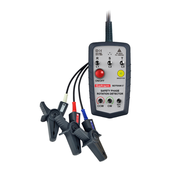
5. Face avant / face arrière Buzzer Indicateur de phase ouverte Réglage de luminosité LED pile faible Ordre de phase... - Page 9 Aimants Etiquette de sécurité Couvercle pile Aimants Les aimants pour le montage sont équipés à l’arrière de ce produit permettent une utilisation mains libres.
-
Page 10: Mise En Œuvre
6. Mise en œuvre Pour utiliser votre appareil, bien lire ce qui suit. 1. Appuyez sur le bouton M/A. Toutes les LED clignotent pendant 2s et seule la LED M/A reste allumée. Ne pas utiliser le testeur si une des LEDs ne fonctionne pas. - Page 11 Les symboles “▼” doivent passer par le centre du conducteur. 3. Effectuez une mesure sur un conducteur sous tension (>75V AC) pour s’assurer que votre testeur fonctionne. 4. La présence de phases ainsi que l’ordre des phases s’affichent sont données par les LED et le buzzer dès que la détection est effective..
-
Page 12: Indication Des Résultats
7. Indication des résultats Etat Indication LED R, S, T allumées si sous Sous tension tension Le testeur ne donne pas Terre absente cette indication La phase avec une LED Terre qui clignote est la terre du (système triangle) système La LED verte CW s’allume si les phases sont correctes Sens «... - Page 13 8 Maintenance ● Remplacement de la pile: lorsque la LED BAT. OK clignote, il faut remplacer la pile Pour cela: (1) Débranchez les pinces crocodiles de l’application sous test. (2) Ouvrir le compartiment pile avec un tournevis (1 vis). (3) Remplacer la pile par une pile 9V (6F22) alcaline, en respectant la polarité.
- Page 14 ● Nettoyez périodiquement votre testeur avec un chiffon doux et humide. Ne jamais utiliser de solvant. ATTENTION Lorsque votre testeur est à l’arrêt, le courant résiduel consommé est de 25uA. Si vous n’utilisez pas votre testeur pendant plus de 60 jours, nous vous conseillons d’enlever la pile afin d’éviter sa décharge.
- Page 15 SEFRAM 32, Rue Edouard Martel- BP 55 42009 SAINT-ETIENNE Cedex 2 Tel : 04 77 59 01 01 Fax : 04 77 57 23 23 Web : www.sefram.fr E-mail : sales@sefram.fr...
- Page 17 SEFRAM 87 Non-Contact SAFETY PHASE ROTATION DETECTOR INSTRUCTION MANUAL M 9087 A00...
- Page 18 INDEX PAGE 1. INTRODUCTION........2. SAFETY NOTES........3. FEATURES..........4. SPECIFICATIONS........5. INSTRUMENT LAYOUT......6. MEASUREMENT........7. LIVE WIRE CHECK........ 8. MAINTENANCE........11-12...
-
Page 19: Introduction
1. INTRODUCTION This Non-Contact PHASE DETECTOR has been designed and tested According to CE Safety Requirements for Electronic Measuring Apparatus, IEC/EN 61010-1 and other safety standards. Follow all warnings to ensure safe operation. WARNING READ "SAFETY NOTES" (NEXT PAGE) BEFORE USING THE NON-CONTACT DETECTOR. -
Page 20: Safety Notes
2. SAFETY NOTES 1. Read the following safety information carefully before attempting to operate or service the detector. 2. Use the detector only as specified in this manual. Otherwise, the protection provided by the detector may be impaired. 3. This instrument cannot find the missing line of earth line (S line). - Page 21 (5) Relative humidity 80% max. (6) Ambient temperature 0~40°C. 11. Observe the International Electrical Symbols listed below: Detector is protected throughout by double insulation or reinforced insulation. Warning! Risk of electric shock. Caution! Refer to this manual before using the detector. AC..Alternating current.
-
Page 22: Features
3. FEATURES ● The meter is a phase detector with LED display lights and beeping buzzer to inform the detection of AC 3-phase sequence. ● Two functions in one unit: open phase and phase sequence. ● Auto-off. (5 min Approx.) ●... -
Page 23: Specifications
4. SPECIFICATIONS Measurement Static induction Principle Input Voltage 75~1000Vac Frequency Range 45~65Hz 5 min. after power on without Auto-Off detection Power LED flashes at 7V ± Low Battery Warning 0.2 or less Current consumption 20mA Operating Temperature & 0°C~40°C Max. 80% R.H. Humidity Storage temperature -10°C~50°C Max. -
Page 24: Instrument Layout
5. INSTRUMENT LAYOUT Buzzer Open phase indicator Brightness Button Power Button Battery LED Phase sequence LEDs... - Page 25 Magnet Warning label Battery cover Magnet Magnets for mounting is equipped on the back of this product allow for hands-free use.
-
Page 26: Measurement
6. MEASUREMENT Before proceeding with measurement, read the safety notes. 1. Press the power button to turn on the instrument. All of the LEDS will flash during the 2 seconds. Only the power LED stays on at the self demonstration later. Do not use the instrument when any of the LEDs do not work. - Page 27 Lines connecting the apexes of "▼" marks should pass through the center of the conductor. 3. Measure a covered conductor AC75V or more first to confirm each live LED lights up. 4. Presence of live wires and phase sequence are informed by LED indication and buzzer beeping as soon as complete detection.
-
Page 28: Live Wire Check
7. LIVE WIRE CHECK State Indication Phase with R, S, T ON is Live live state Missing line of Earth LED does not light up for line missing line of earth line Earth line Phase with flashing LED is (Delta connection) an earth phase When the Green CW LED ON, the circuit is forward... -
Page 29: Maintenance
8. MAINTENANCE ● Battery replacement: When low battery LED flashes, replace with new batteries. Follow these steps for battery replacement: (1) Remove all the clips from the conductors and power off the instrument. (2) Loosen the screw that secures the battery compartment cover and open cover. - Page 30 ● Cleaning and storage Periodically wipe the case deterged with a damp cloth; do not use abrasives or solvents. WARNING After the instrument has been turned off, the standby current is below 25uA. If the meter is not to be used for periods of longer than 60 days, remove the batteries and store them separately.
- Page 32 SEFRAM 32, Rue Edouard Martel- BP 55 42009 SAINT-ETIENNE Cedex 2 Tel : 04 77 59 01 01 Fax : 04 77 57 23 23 Web : www.sefram.fr E-mail : sales@sefram.fr...
Need help?
Do you have a question about the 87 and is the answer not in the manual?
Questions and answers