Table of Contents
Advertisement
Quick Links
Download this manual
See also:
User Manual
Advertisement
Table of Contents

Related Manuals for SEFRAM BK Precision DAS30


Summary of Contents for SEFRAM BK Precision DAS30
- Page 1 Test Equipment Depot - 800.517.8431 - 99 Washington Street Melrose, MA 02176 - TestEquipmentDepot.com User Manual DAS30 / DASSO / DAS60 High Speed Multi-Function Recorders...
- Page 2 Safety Summary The following safety precautions apply to both operating and maintenance personnel and must be followed during all phases of operation, service, and repair of this instrument. Before applying power to this instrument: • Read and understand the safety and operational information in this manual. •...
- Page 3 Electrical Power This instrument is intended to be powered from a CATEGORY II mains power environment. The mains power should be 115 V RMS or 230 V RMS. Use only the power cord supplied with the instrument and ensure it is appropriate for your country of use.
- Page 4 Do not operate instrument if damaged If the instrument is damaged, appears to be damaged, or if any liquid, chemical, or other material gets on or inside the instrument, remove the instrument’s power cord, remove the instrument from service, label it as not to be operated, and return the instrument to B&K Precision for repair.
- Page 5 Do not substitute parts that are not approved by B&K Precision or modify this instrument. Return the instrument to B&K Precision for service and repair to ensure that safety and performance features are maintained. For continued safe use of the instrument •...
-
Page 6: Table Of Contents
Contents Introduction Recording Modes 1.1.1 Direct mode 1.1.2 Memory mode 1.1.3 Go No-Go mode 1.1.4 File mode 1.1.5 Power Analysis mode Getting Started Measurement Types Powering the Recorder Connections 2.3.1 Analog Inputs Ground the Recorder Thermal Printer 2.5.1 Loading Paper 2.5.2 Storing Printed Recordings Power-up Configuration... - Page 7 Direct Mode Launching the printing Configuration of print 6.2.1 Relaunching the printing 6.2.2 Writing information Memory Mode Setup and start of the data acquisition Sampling period Internal memory, blocks Trigger position Double Trigger mode Recording Memory output File Mode Setup and triggering of the data acquisition Restrictions Go/No Go Mode Setup and launching of the data acquisition...
- Page 8 11 Channel Setup 11.1 Analog channels 11.2 Type of measurement ΔV/ Δt 11.2.1 Example 11.2.2 Type of measurement ∫ �� ���� 11.2.3 Example 11.3 Additional functions between channels 12 Triggers 12.1 Analog channel trigger 12.1.1 Single threshold 12.1.2 Multiple thresholds 12.1.3 Example 12.1.4...
- Page 9 17 Specifications 18 LIMITED TWO-YEAR WARRANTY 19 Service Information...
-
Page 10: Introduction
Introduction The DAS30, DAS50 and DAS60 programmable recorders measures and records voltage, current, temperature, etc. on up to 6 channels. The recorders also include digital input capabilities using the 12 logic input channels. An optional feature of the recorders is a port for measuring temperature with Pt100 or Pt1000 temperature sensors. 1.1 Recording Modes Finally, the optional thermal printer adds the ability to print recorded signals (saved and in real-time). -
Page 11: Getting Started
Getting Started You turn on the recorder by pressing the button at the top of the device. When the device is on, the ON/OFF button is lit blue. After launching the software, the recorder displays a homepage that specifies the hardware version, then switches auto- matically to the «... -
Page 12: Analog Inputs
DAS60 DAS50 Item Description DC Power PT100-PT1000 (optional) Power Switch USB Ports Ethernet Port Logic Signal Connector Analog Inputs Grounding Terminal DAS30 Figure 2.1 Recorder Connections 2.3.1 Analog Inputs Isolated inputs have 2 shielded banana jack type terminals for each input: Positive Input Negative Input Black... -
Page 13: Thermal Printer
2.5 Thermal Printer The DAS30, 50 and 60 recorders may be ordered with a thermal printer. The printer prints to 110mm wide thermal paper. Paper must always be loaded in the printer to avoid printing without paper and risking damage to the thermal print heads. -
Page 14: Battery
2.8 Battery The device is equipped with a lithium-ion battery (Li-ion) that should last at least 200 full charge cycles. It is shipped charged. Upon reciept or if the device has remained unused for more than one month, check its status and recharge if necessary. -
Page 15: Default Calibration
1. Let the device work for 20 minutes (ambient temperature 68 - 77 F) 2. Enable all desired channels in the channel configuration menu 3. Short the terminals of the active channels 4. Go to the setup menu 1. Press 2. -
Page 16: Locking Of The Recorder
2.13 Update of the internal software Software updates to the recorders may be available. These updates are available on the Sefram website in the “Software Updates” section. Only update the recorder when connected to power and/or with a charged battery. -
Page 17: Home Screen
Home Screen The home screen provides access to all of the settings and functions of the recorder. It is accessed by pressing Item Description Item Description “Direct Mode” Logic Setup “Memory Mode” X-Y Plotting “File Mode” Start Recording “Go/No Go Mode”... - Page 18 Figure 3.2 Single Analog Channel Configuration Screen Test Equipment Depot - 800.517.8431 - 99 Washington Street Melrose, MA 02176 - TestEquipmentDepot.com...
-
Page 19: Setup Screen
Setup Screen General configuration of the device, monitoring of the alarm outputs, network address TCP/IP, calibration of the channels, update of the internal software. Figure 4.1 Setup Screen 1. Language: 2. Screen shutoff time setting 3. System time settings 4. Graphic Options: The display orientation of the data in the bargraph (Item Right Max value to the right... -
Page 20: Logic Channels
5. Additional option: More settings 6. Software update: update of the internal software (see chapter Presentation) 7. Default setup: Set all settings to default values 8. Load on disk: load a stored configuration from memory (internal or USB drive) 9. Save on disk: save the current configuration to memory (internal or USB drive) 10. -
Page 21: Real Time On-Screen Display Of The Measurements
Figure 4.3 1. Selection of the name of each channel on screen 2. Selection of the color of each channel on screen 3. Logic validity: validation of the data acquisition and plotting of the logic channels 4. Validation of the channels You can validate or not the channels to record or print out in the various configuration menus of the recorder. - Page 22 Figure 4.4 Figure 4.5 You get access to:...
- Page 23 Relaunch – relaunches the sweep displays the vertical cursors (2) to make measurements on the screen; move the cursor by select- Time Cursors ing it with your fingers or the mouse. Voltages Cursors displays the horizontal cursors (2) to make amplitude measurements on the screen; pro- ceed like for the time cursors to move them.
-
Page 24: Xy Display
7. Modification of the position of the selected channel (with the « + », « - » and central keys). 8- Time base: Allows you to adjust the time base. 8. Back to the previous page. 4.3 XY display The XY display mode makes it possible to display the validated channels in real time one against the other. One of the channels defines the horizontal axis;... -
Page 25: Trigger Menu
Figure 4.8 4.5 Trigger menu Programming the start and stop conditions for the paper print in Direct mode, and the data acquisition conditions for the channels in Memory, File and Template modes. Selection of the actions after data acquisition or plot and validation of the save in real time. Figure 4.9 The program of triggers is different according to the pending mode (Direct, Memory, File or Template). -
Page 26: Record Key
Figure 4.10 This function includes the same commands as the « Direct display » function. The « Read block or file » command allows you to select the memory block (zone inside the internal memory) or the file to display. When pressing this key, the following window pops up: Figure 4.11 •... -
Page 27: Screen Copy
Memory mode: launches the data acquisition into internal memory; the device waits for the start condi- tion Template mode: launches the data acquisition into internal memory; the device waits for the start condi- tion mode: launches the data acquisition into file; the device waits for the start condition File Network analysis mode: real time data acquisition directly into the internal memory (there is no trigger) -
Page 28: File Management
FILE MANAGEMENT General For all possible files, the device has an internal flash disk available and may accept an USB stick, which makes it possible: • to save and load the total configuration of the recorder • to save or restore a data acquisition. The names of the setup files have a “cnf”... -
Page 29: Save Setup Files
Load from disk : loads a configuration from a file in the internal flash disk or an USB stick Save to disk : saves a configuration into a file in the internal flash disk or an USB stick Save ASCII file to disk : saves a configuration into ASCII file in the internal flash disk or an USB stick 1 Save setup files Press Save to disk... -
Page 30: Recovery Of The Data Acquisition Files
Name of the files: the name of each file is made of 12 characters plus one 4-cipher number. The device will automatically increase this number at each record. Only the validated channels (i.e. in ON position; see chapter Use) will be recorded into the file. Before writing into the file, a pop-up reminds you the saved channels and the number of points per channel. -
Page 31: Display Under Seframviewer
You can create a favorite icon: • Go to Tools → Connect to a network driver • Click Open a storage session or a network server • Under Internet network address , type ftp:// and the IP address of the recorder. You can give a name to this link that will always be active among network favorites . - Page 32 • Manage setups (creation and change setup files) • Start and stop records • Load data blocks • Load files thanks to Windows Explorer through FTP • Launch SeframViewer • Real time display of data in F(t) format...
-
Page 33: Direct Mode
Direct Mode This chapter describes the Direct mode of the recorder, designed to print out the measurements made on the channels in real time on heat-sensitive paper. This mode does not exist on models without integrated printer. You can start and stop the print out under various conditions. You can activate a simultaneous save of the measurements on file. -
Page 34: Configuration Of Print
4. Stop: stop condition of the print − Manual: with the − Trigger: with a channel, with a combination of analog and logic channels (see chapter 5) − Stand-by: after a delay or at a precise date and time − Paper length: after printing a programmed length of paper 5. -
Page 35: Relaunching The Printing
Reticule : setup of the reticule on paper • none, all 5mm, 10mm or per integer number of divisions • fine or wide, which means with or without subdivisions • access to the « Modification of diagrams » to setup the display of channels on paper (see chapter Diagrams) Name of the plot setup of a title (80 characters max.) for printing. -
Page 36: Memory Mode
Memory Mode This chapter describes the Memory mode designed to record in real time the measurement data made on the channels into the internal memory. You can start and stop the data acquisition under various conditions. You can simultaneously save measurements on file. 7.1 Setup and start of the data acquisition Setup of the data acquisition into internal memory. -
Page 37: Sampling Period
4. Stop: stop condition of the data acquisition − Automatic: when the block is full − Trigger: with a channel, with a combination of analog and logic channels (see chapter 5) − Trigger mode: Double Trigger; see the following chapter. 5. -
Page 38: Trigger Position
When all blocks are full, any new data acquisition will shift the previous blocks from the N position into the N-1 position; the 1 block will be lost. The new data acquisition will take the place of the last block. 7.4 Trigger position The data acquisition into a memory block relies on the concept of «... - Page 39 If the acquisition time of the record is less than 2 minutes, you will see the whole data acquisition. Then, you won’t be able to leave this page: only when the acquisition stops can you change of menu. Figure 7.3 For longer acquisition time, you can zoom onto a part of the data or change of page.
-
Page 40: Memory Output
• Partial : only a part of the memory is displayed; the screen is frozen; only the bargraph and the filling rate show the status of data acquisition; you have access to time cursors and zooms. You cannot visualize a block else than the current one, draw a plot or save the data acquisition into a file as long as the current data acquisition is not finished. - Page 41 • the date of trigger • the number of points per channel in the block • a bargraph showing the filling level of the block and the position of the trigger...
-
Page 42: File Mode
File Mode This chapter describes the File Mode designed to record in real time the measures made on the channels. The start and stop of the plot can be triggered under various conditions. 1 Setup and triggering of the data acquisition Press Figure 8.1 1- File name: directory and name of the data acquisition file... -
Page 43: Restrictions
Trigger mode Double Trigger; see chapter Memory mode. 8.1 Restrictions Real time data acquisitions to a file are limited by the transfer rate between the inputs and the saving means of the internal memory or USB sticks. It is advisable no to create too big files, because reading them may be very long. It takes ca. 3 minutes to read a 200MB file. -
Page 44: Go/No Go Mode
Go/No Go Mode This chapter describes the “Go/No Go” designed to record in real time the measurement data made on the channels into the internal memory. You can start the data acquisition under various conditions It stops when the measurement values go out of a range defined by a previous data acquisition called Template. -
Page 45: Start: Start Condition Of The Data Acquisition
9.4 Start: start condition of the data acquisition • Manual: with the key. • Trigger: with a channel, with a combination of analog and logic channels (see chapter 5) • Stand-by: after a delay or at a precise date and time 9.5 Automatic: automatic stop when the block is full 1. -
Page 46: Use Of The Template
Figure 9.2 9.6 Use of the template The comparison with the template is the stop criterion of the data acquisition. This comparison shall be made with the « Template Channels » selected in the page. The information window at the bottom of the page sums up the general configuration of the data acqui- sition: •... -
Page 47: Power Analysis Mode
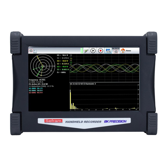
Power Analysis Mode The recorder also includes a network analysis function. It allows power and harmonics measurements. Measured values can be viewed in real time or delayed. You can also record the available logic channels and channels. You can access the network analysis menu with the key. -
Page 48: Network Setup
Figure 10.2 • Selection of the type of analysis and of the desired values You can also access other menus: • Visualization (Oscilloscope, Digital, Harmonics): key. • Acquisition: key. Attention: The connections of the inputs on the installation to test shall be made by a duly authorized personal. In network analysis the DAS60 should be strictly connected to its external power supply and connected to the socket : this for security reasons ensuring earthing. -
Page 49: Wiring And Check
Figure 10.3 • Voltage measurement: « Direct » or « Transformer ». If the network voltage is measured through a transformer, select this setup and enter the transformation ratio • The device automatically selects the right caliber; you only have to specify the nominal voltage of the networks. Beware: if this value is too different from the real voltage, this may lead to uncertainty and measurements over the caliber •... -
Page 50: Fresnel Diagram
10.4 Fresnel diagram You can also check if the wiring is right by displaying the Fresnel diagram. The length of the arrows is not proportional to the efficient value of the currents: the user will have to check that what he sees is coherent. The position of the voltage arrows is calculated with reference to the voltage V1. - Page 51 Figure 10.6 Figure 10.7 • Fresnel diagram: display of the signal and of the RMS values of the inputs and of the frequency. • Oscilloscope: This mode allows you to know the true shape of the signals; hence, it will help you detect wiring mistakes.
-
Page 52: Power Analysis Setup
− Selection of the channels: you select either all the voltage channels (U1, U2, U3) or all current channels (I1, I2, I3) or all network channels (U1, U2, U3 + I1, I2, I3) or only one channel (these channels are also used to record harmonics. -
Page 53: Automatic Trigger
10.10.2 Automatic trigger You only have to press the record key to launch the record,but no stop condition is possible unless manually. 10.10.3 Parametric trigger The record is launched according to a TRUE condition of a given parameter, of a value and of a comparison. You will find the list of the parameters you can use at 10.11 You can select a stop condition (recording time or manual stop) Figure 10.9... -
Page 54: In Version 1.1 Of The Firmware Or Later
Threshold: reference value in Ampere RMS where the record will start. Hysteresis: Percentage value of the tolerance for the start according the selected threshold. If you want no tolerance, set the value to 0 %. You can start the record after starting the motor: the next trigger will be the next overintensity if the evolution of current is under the low threshold (threshold * hysteresis/100) and reaches the threshold. -
Page 55: Record
• Validity: : allows you or not to display a parameter as a graph; the parameters will always be recorded; only the graphic display is changed. • Color: color of the displayed parameter in the graph; for the additional channels and the logic channels, the colors are as set up for each of them •... -
Page 56: Measurement Process
10.14 Measurement process �� ∑ �� Efficiency Values = √ �� ��=1 �� ������ �� �� Avergage Values �� ∑ �� �������� �� �� ��=1 �� Active Powers �� = ∑ �� ∗ �� �� �� �� ��=1 Apparent Powers ��... -
Page 57: Channel Setup
Channel Setup Figure 11.1 Change of the color of the channel (by pressing this button, you can access pre-defined colors or design customary paint mixes: Figure 11.2 Change the thickness of the line for the selected channel. You can also change this thickness with the (thicker) keys 1. -
Page 58: Analog Channels
Figure 11.3 This table gives you a quick insight of the various adjustments of the channels. You can change these adjustments directly in this table by pressing the parameter you want to update. You can access the setting of parameters channel by channel by pressing the name of the channel at the top of the table (A1, A2…) or by pressing on the bargraph of the channel (right side of the screen). -
Page 59: Type Of Measurement Δv/ Δt
4. Type of external sensor 5. Filter: positioning of a filter on the input − 10kHz, 1kHz, 100Hz, 10Hz for analog filters − 1Hz, 10s, 100s or 1000s for the digital filters (according to the type of signal) 6. Change of the color of the channel 7. -
Page 60: Example
Figure 11.5 Put on the « derivative » measurement mode. ΔV/ Δt Every period Δt, the recorder divide the voltage variation by Δt and get a value in Volt/second. Select the measurement range of the input signal from +-500µV to +-500V. The range must be ΔV larger than the input signal. -
Page 61: Example
Figure 11.6 Figure 11.7 11.2.3 Example Channel 1: square signal, period 10s, 2s at 5V, 8s at 0V . Channel 2: use measurement type V.dt with the same signal V +-10V dt 200 µs Span 200Vs The signal « integral » (channel 2) begin at 0Vs and then increase of 10Vs (integration of 5V during 2s) every signal (Channel 1) period. -
Page 62: Additional Functions Between Channels
Figure 11.8 11.3 Additional functions between channels There are function channels on this device. You can activate up to 4 function channels (FA, FB, FC, FD). These channels make it possible to make calculations between channels or calculations of average values… For example, if you want to calculate a value of power, select the parameters of the A function channel Figure 11.9 You get this page above. - Page 63 Figure 11.10...
-
Page 64: Triggers
Triggers This chapter describes all possible triggers of the device. They are used by: • the « configuration » menu, with the A and B alarms • the « triggers » menu, with the start and stop parameters of the recording. •... -
Page 65: Multiple Thresholds
Figure 12.2 1. Channel: selection of the channel, on which the trigger threshold is applied 2. Threshold 1 / Threshold 2: selection of the threshold to settle; each channel is tested with reference with 2 thresholds, i.e. you can program a start condition on the channel A1 and the threshold 1, and a stop condition on this same channel A1 and the threshold 2. -
Page 66: Example
1. One of the thresholds (or): the first achieved condition activates the trigger 2. All thresholds (and): all conditions must be simultaneously achieved to validate the trigger 3. Slope (ou): trigger on the slopes of the signals; the first achieved condition validates the trigger 12.1.3 Example The trigger displayed above is: Trigger if... - Page 67 Figure 12.5 Test Equipment Depot - 800.517.8431 - 99 Washington Street Melrose, MA 02176 - TestEquipmentDepot.com...
-
Page 68: Math Functions
Math Functions You can apply mathematical calculations on your data acquisitions. You can access them with the « Direct display » function. 13.1 Definitions Press the « Mathematical calculations » key. Figure 13.1 Add: add a mathematical calculation remove one of the displayed mathematical calculations Remove: Channel: selection of the channel on which the calculation is applied... -
Page 69: Math Functions
Figure 13.2 13.2.1 Math Functions Math function values may be moved around on the screen. To move the math values, click and drag them to a desired position on screen. Minimum Maximum Peak to Peak The most frequent value below the median High The most frequent value above the median Amplitude... - Page 70 Duration of N complete periods Average duration of a complete cycle calculated Cycle average �� on as many periods as possible T1 = 10% Amplitude T2 = 90% Amplitude Trise = T2 - T1 Rising edge T1 = 90% Amplitude T2 = 10% Amplitude Tfall = T2 - T1 Falling edge Positive pulse width Measurement of the time of 1st positive pulse.
-
Page 71: Input - Output
Input - Output 14.1 Additional Input/Output Connectors The connector is at the rear (female SUB-D 25pin). Figure 14.1 # pin I/O Name of the signals Logic channel 1 Logic channel 2 Logic channel 3 Logic channel 4 Logic channel 5 Logic channel 6 Logic channel 7 Logic channel 8... -
Page 72: Use
Figure 14.2 Logic Input Non-connected inputs are 0V potential (level 0). Number of logic channels: from 1 to 16. TTL level: 3.3V (protected up to 24V) To create a rising edge, you only have to place a connection between the power input and output of the connector. Similarly, to create a falling edge, you only have to remove this connection. -
Page 73: External Voltage Box Input/Output Interface
The power supply may disappear in case of overload (> 0.2A). In this case, you must turn off the device a few minutes before turning it on again. 14.5 External voltage box input/output interface The external voltage box input/output interface option (code 984405500) makes it possible to: •... - Page 74 Figure 14.3...
-
Page 75: Ethernet Interface
You can create your own software under Visual Basic, Visual C++, etc. by using, for example, the Winsock.dll driver by Microsoft. Then, you only have to send the commands as per the following paragraphs to the recorder. 15.2 WIFI interface Use only the USB stick provided by SEFRAM. -
Page 76: Ftp Transfer
Turn the device on with the USB stick on a relevant port. In the « Setup » menu, press the « Network » key. Once the Wi-Fi validated, press the « Wi-Fi networks » key. Figure 15.1 (if you don’t see your network, press the Ethernet/Wi-Fi keys several times) When your network appears, select it and validate. -
Page 77: Managing With Vnc
15.4.1 Changing the password In the « Setup » page, press VNC. You can then change the password of VNC. The default password is « sefram ». 15.4.2 External software VNC Viewer You are submitted a link to easily download this software: http://www.realvnc.com/download/viewer/. -
Page 78: Programming
Programming 16.1 Message Format Note: In all the following examples, the space character is pictured as a blank space. Exchanges from a controller to the recorder are made as messages made of a chain of ASCII characters (and possibly of binary bytes) with a message termination at the end. -
Page 79: Data Separator
16.3.4 Data separator A comma "," possibly followed and/or preceded by one or several "filling" characters in ASCII code (0 to 32, decimal except 10 and 13). 16.3.5 Data There are several types of data: 16.3.5.1 Alphanumeric data 1 to 12-character words that can be alphabetic (upper case or lower case), digital or "_" (95d) coded under ASCII. Words always start with an alphabetic character. -
Page 80: Data
Data separator Comma ",". 16.4.2 Data There are several types of data: Alphanumeric data 1 to 12-character words that can be alphabetic (upper case only), digital or "_" (95d) coded un- der ASCII (example: J). Decimal digital data Made of a chain of ASCII characters starting with a cipher or a sign (+ or -). They are of NR1 (integer), NR2 (decimal) or NR3 type (with exponent). - Page 81 Specifications Note: All specifications apply to the unit after: 1. A temperature stabilization time of 15 minutes over an ambient temperature range of 23 C ± 5 ∘ ∘ 2. Short correction operation performed before making measurement. Specifications are subject to change without notice.
- Page 82 High speed multi-function recorders Models DAS30 / DAS50 / DAS60 Specifications Note: All specifications apply to the unit after a temperature stabilization time of 30 minutes over an ambient temperature range of 23 °C ± 5 °C. Universal Inputs Power Analysis Function Networks Single phase, 3 phase DAS30...
- Page 83 LIMITED TWO-YEAR WARRANTY B&K Precision Corp. warrants to the original purchaser that its products and the component parts thereof, will be free from defects in workmanship and materials for a period of two years from date of purchase. B&K Precision Corp. will, without charge, repair or replace, at its option, defective product or component parts. Returned product must be accompanied by proof of the purchase date in the form of a sales receipt.
- Page 84 Service Information Test Equipment Depot - 800.517.8431 - 99 Washington Street Melrose, MA 02176 - TestEquipmentDepot.com...
Need help?
Do you have a question about the BK Precision DAS30 and is the answer not in the manual?
Questions and answers