Table of Contents
Advertisement
Quick Links
– 7871 - 7872 - 7875 - 7876 –
7871-7872-7875-7876
EXPERT TV METERS
USER MANUAL
This product contains one or more programs protected under international and US copyright laws as un-
published works. They are confidential and proprietary to Dolby laboratories. Their reproduction or disclo-
sure, in whole or in part, or the production of derivative works there from without the express permission of
Dolby Laboratories is prohibited. Copyright 2003-2005 by Dolby Laboratories. All rights reserved.
May 2015
M7875001A/05
Advertisement
Table of Contents

Subscribe to Our Youtube Channel
Related Manuals for SEFRAM 7871


Summary of Contents for SEFRAM 7871
- Page 1 – 7871 - 7872 - 7875 - 7876 – 7871-7872-7875-7876 EXPERT TV METERS USER MANUAL This product contains one or more programs protected under international and US copyright laws as un- published works. They are confidential and proprietary to Dolby laboratories. Their reproduction or disclo- sure, in whole or in part, or the production of derivative works there from without the express permission of Dolby Laboratories is prohibited.
- Page 2 – 7871 - 7872 - 7875 - 7876 – Revision follow-up Version / Date Page or § Changes 1.0 / March 2013 First manual 2.0 / April 2013 9.5.1 Electronic compass 13.5, 13.6 Add « (not available for 7871 and 7872) »...
- Page 3 – 7871 - 7872 - 7875 - 7876 – Thank you for purchasing this SEFRAM product and therefore trusting our company. Our different teams (research department, production, sales department, after-sales service…) are aiming at satisfying your wishes by designing and updating very advanced appliances.
- Page 4 It shall subscribe, at its own expenses, any insurance required for the transport. The SEFRAM company reserves the right to refuse any product wrongly conditioned and not to take in charge any break consecutive to the transport.
- Page 5 – 7871 - 7872 - 7875 - 7876 – Some advice! Some technical help! SEFRAM Instruments & Systèmes commits itself to help you on the phone about the use of your appliance. Please call or Technical Support: Or e-mail: support@sefram.fr We thank you for your trust.
-
Page 6: Table Of Contents
– 7871 - 7872 - 7875 - 7876 – TABLE OF CONTENTS Important information ......................10 Particular precautions ........................... 10 Security instructions ............................. 10 Symbols and definitions ..........................10 Conformity and restrictions of the appliance ....................11 Quick start-up ........................12 Presentation of the appliance ........................ - Page 7 – 7871 - 7872 - 7875 - 7876 – Double Check Sat ............................47 Alignment of the satellite dish ........................47 9.5.1 Electronic compass ..........................48 9.5.2 Recall ..............................49 10 The Measures-TV-Spectrum page ..................50 11 Measures ..........................51 11.1...
- Page 8 – 7871 - 7872 - 7875 - 7876 – 14.1 Terrestrial band ............................74 14.2 Satellite band ............................75 14.2.1 Launching .............................. 75 14.2.2 Switches ..............................76 14.2.3 Positioner .............................. 77 14.2.4 DCSS ..............................78 14.2.4.1 Influence of the DCSS on the spectrum analyzer................80 15 Constellation ........................
- Page 9 – 7871 - 7872 - 7875 - 7876 – 24.3.2 Export and cartography ........................109 25 Optical Power Measurement ................... 111 26 WIFI ........................... 112 27 HDMI Connection ......................113 28 Displayed messages ......................114 28.1 Alert messages ............................114 28.2...
-
Page 10: Important Information
In case of failure or for the maintenance of the appliance, only a qualified personal shall be entitled to work on it. In such a case, it is required to use Sefram spare parts. Do not open the appliance: risk of electric shock. -
Page 11: Conformity And Restrictions Of The Appliance
– 7871 - 7872 - 7875 - 7876 – Symbols on the appliance: Attention: Refer to the manual. Shows a risk of damage for the material connected to the instrument or to the instrument itself. Ground: Grounded accessible parts. Product for recycling. -
Page 12: Quick Start-Up
– 7871 - 7872 - 7875 - 7876 – 2 Quick start-up Presentation of the appliance RF connector for use with a BNC/F or F/F adaptor provided with the appliance. Pour brancher le signal à analyser Press button ON/OFF Important keys: 787X is an appliance with a capacitive touchscreen. -
Page 13: Signal Spotting
– 7871 - 7872 - 7875 - 7876 – Attention: To exit a window like in this example below, press the key: Signal spotting The 787X allows spotting signals in ground or very quick satellite mode. In the following chapter, we will see how to spot a signal on three types of installation: ... - Page 14 – 7871 - 7872 - 7875 - 7876 – Press START. The appliance searches until the end of the scan and turns directly to the Measurement plan mode. If channels were found, the appliance makes measurements continuously (C/N-level, then BER/MER) on the detected channels.
-
Page 15: Installation Of A Terrestrial Antenna
– 7871 - 7872 - 7875 - 7876 – 2.2.2 Installation of a terrestrial antenna Plug the cable of your antenna to the 787X (take care to use an adequate adaptor) Turn your appliance on. Press the Measures-TV-Spectrum key Press the Spectrum zone... - Page 16 – 7871 - 7872 - 7875 - 7876 – Press directly the signal you want in the spectrum (the cursor moves to where you press) Press the NIT/TV key , the device find automatically all the parameters of the signal.
-
Page 17: Installation Of A Satellite Dish
– 7871 - 7872 - 7875 - 7876 – 2.2.3 Installation of a satellite dish Connect the satellite dish to the appliance. Activate the remote power supply To access to the Remote power supply page, press To launch the remote power supply en route, press... - Page 18 – 7871 - 7872 - 7875 - 7876 – Slowly orientate the satellite dish until hearing the locking melody and getting the best quality No found transponder → red smiley Average reception quality (< 50%) → orange smiley Good reception quality (> 50%) → green smiley...
- Page 19 – 7871 - 7872 - 7875 - 7876 – Attention: To identify a satellite, you must be « hooked » on all 4 transponders. (Quality > 0) However, some transponders are regularly modified. See the frequency range of the satellite when a transponder does not seem to work.
-
Page 20: Presentation
– 7871 - 7872 - 7875 - 7876 – 3 Presentation General The field strength measurers 787X are handy appliances designed for the installation and maintenance of any broadcasting and reception installations of analogical and digital terrestrial television channels, satellites or cable networks. -
Page 21: Description Of The Appliance
– 7871 - 7872 - 7875 - 7876 – Description of the appliance FRONT VIEW 10’’ capacitive Fastening touchscreen for straps high resolution TNC GPS socket (option) BNC ASI OUT socket (option) SMA WIFI socket (option) BNC ASI IN socket (option) - Page 22 – 7871 - 7872 - 7875 - 7876 – How to use the belts For carrying properly your instrument, we suggest to set the belts as shown on the picture below (upside on the left and bottom on the right)
-
Page 23: Power-Up
– 7871 - 7872 - 7875 - 7876 – 4 Power-up All the material is checked before shipment and delivered in an adapted packaging. There is no particular unpacking instruction. The appliance is equipped with a Lithium-Ion (Li-ion) battery. It is shipped with the battery loaded. -
Page 24: External Power Supply
– 7871 - 7872 - 7875 - 7876 – Loading will be faster if the appliance is off but will work if the appliance is on. Once the battery loaded, the lamp will shut off automatically. Discharge the appliance only with the provided power supply block. -
Page 25: Man-Machine Interface
– 7871 - 7872 - 7875 - 7876 – 5 Man-machine interface Content of the screen 787X is an appliance with a capacitive touchscreen. This requires a soft handling. No glove and no stylus should be used, so that the triggering should be taken into account. - Page 26 – 7871 - 7872 - 7875 - 7876 – On all pages is displayed the following information: Indication of the values Indication of the position of the Page title Site name Tension and Current of switch or of the SatCR (position...
-
Page 27: Changing A Name Or A Value
– 7871 - 7872 - 7875 - 7876 – To navigate through a table inside a page or a window, a vertical slide appears with arrows to move up and down the table. To move faster, you can slide a cursor with your fingers. -
Page 28: Change With Selection
– 7871 - 7872 - 7875 - 7876 – 5.2.2 Change with selection When pressing a key, you may have a window with multiple choice. You only have to press the value you want to validate it. The key allows you to cancel and exit this window, like in the example below. -
Page 29: Lists Of Measurements And Setup Library
– 7871 - 7872 - 7875 - 7876 – Lists of measurements and setup library In order to make easier the recall of data on field, the appliance uses 20 measurement lists of each 50 lines and 1000 setups. A setup corresponds to a terrestrial, cable or satellite emission. - Page 30 – 7871 - 7872 - 7875 - 7876 – the selection mode of the polarization the presence of the position number of the positioner (motorized satellite dish) 50 lines including each: a setup number corresponding to the setup list ...
- Page 31 – 7871 - 7872 - 7875 - 7876 – According to the terrestrial, cable or satellite band mode and to the standard, some parameters have no influence. The place name may distinguish two distinct emitters, example TF1 Fourvière and TF1 Chambéry.
-
Page 32: Autoset Mode
– 7871 - 7872 - 7875 - 7876 – 6 AUTOSET mode Attention: The Autoset channel research is only possible when at least one list is empty with enough place in the library This mode allows an automatic research of setups and to provide information about the current place. -
Page 33: Terrestrial Mode
– 7871 - 7872 - 7875 - 7876 – A green check shows that the parameter is included in the research. If there is no green check, the parameter will not be taken into account for the research. Inactive research parameter Active research parameter Attention: The more you select options, the longer the research. -
Page 34: Cable Mode
– 7871 - 7872 - 7875 - 7876 – Cable mode This mode allows automatic research on the cable frequency band. «START » menu key No matter which mode is selected, press the “START” key when the table is filled to launch the research. - Page 35 – 7871 - 7872 - 7875 - 7876 – Any detected channel will be registered into the first empty list (automatically renamed AUTOSET) and into the fist available setups of the library, starting from the end of the table. The new list is created in the first...
-
Page 36: Measurement Lists
– 7871 - 7872 - 7875 - 7876 – 7 Measurement lists The List page In this page, you can select the list where you will work on measurements. Pressing Home then Lists-Library gives you access to the Lists function: Lists are ranked from 0 to 19. -
Page 37: Modification Of A List
– 7871 - 7872 - 7875 - 7876 – Modification of a list To change the name of a list, you must trigger its name. A virtual keypad shows up. Type the new name (SEFRAM in our example). To add a setup to the list, select the line. A window shows up: Attention: If the line contains a setup, it shall be erased. - Page 38 – 7871 - 7872 - 7875 - 7876 – Scroll the list up or down to find the setup you want to add to your list. Press the line you want: The setup is now in the list: You may erase the setup from the list by pressing the check before Erase when the setup is selected. You can also erase all setups from the list by pressing the check before Erase all.
- Page 39 – 7871 - 7872 - 7875 - 7876 – In a satellite setup, you can change the switch, the Uncommitted Port and the DCSS by activating any of these keys (this change will affect only the setup in this list, not in the library):...
-
Page 40: Setup Library
– 7871 - 7872 - 7875 - 7876 – 8 Setup library The Library page By pressing Home then Lists-Library , you can access the Lists function. From there, you can access the Library by pressing the key: Creation or modification of setups in the library To create or change a setup in the library, you have to select a line in the table. - Page 41 – 7871 - 7872 - 7875 - 7876 – Terrestrial setup: Under standard DVB-T/H (DVB-T2 identical, except modulation) To enter the place To enter the name you name you want for want for the setup the setup To enter the frequency...
- Page 42 – 7871 - 7872 - 7875 - 7876 – Setup Satellite KU, L or C: Ku L or C corresponds to the selected band To enter the type of polarity you want for the setup (high or low, vertical or horizontal)
-
Page 43: Check Sat
– 7871 - 7872 - 7875 - 7876 – 9 Check Sat Only for satellite band. The Check Sat mode allows you to quickly align the satellite dish by initial selection of the satellite. Press to access the Check Sat mode. -
Page 44: Updating Satellites
– 7871 - 7872 - 7875 - 7876 – Updating satellites You may add new satellites and update or suppress old ones thanks to a computer and an USB memory stick. You can use of free PC software TR7837: download it from our website. -
Page 45: Check Sat Function
– 7871 - 7872 - 7875 - 7876 – Check Sat function Procedure: 1/ Connect the satellite dish to the appliance and start it up. 2/ Validate the remote power supply: VDC lights up. Check the power supply current of the LNB (IDC at the top right corner of the screen should be between ca. -
Page 46: Checking The Aligned Satellite
– 7871 - 7872 - 7875 - 7876 – If the appliance is not synchronized on all four transponders, the quality indication is red. If the appliance is synchronized on all four transponders but the reception quality is average, the quality indication is orange. -
Page 47: Double Check Sat
– 7871 - 7872 - 7875 - 7876 – Double Check Sat This mode allows you to orientate a double LNB by checking 4 transponders on 2 selected satellites. This mode is identical to the simple Check Sat mode To access the double Check Sat mode, you have to trigger the Double key. -
Page 48: Electronic Compass
– 7871 - 7872 - 7875 - 7876 – Calculations: Satellite: satellite to aim, the closest to the median position between Satellite1 and Satellite2 Elevation: tilting angle of the satellite dish Azimuth: horizontal angle of the satellite dish with reference to the north ... -
Page 49: Recall
– 7871 - 7872 - 7875 - 7876 – 9.5.2 Recall Azimuth Position of the satellite dish on the horizontal plane with reference to the north. Measured in degrees. Elevation Tilt angle under which the beam from the satellite reaches your antenna. Measured in degrees using what is specified on the stand of the satellite dish. -
Page 50: The Measures-Tv-Spectrum Page
– 7871 - 7872 - 7875 - 7876 – 10 The Measures-TV-Spectrum page The Measures-TV-Spectrum page is divided in three zones that can each be displayed full screen by pressing it (the spectrum, the TV or the measurement). It also includes a service list zone where you can watch the services of the channel and change of selection if required. -
Page 51: Measures
– 7871 - 7872 - 7875 - 7876 – 11 Measures Pressing the MEASURE zone gives access to the MEASURES function. In this page, you can either perform measurements on a memorized program in the current list (see chapter « Measurement list »), or change parameters manually, or use the AutoLock function 11.1... -
Page 52: Modification Of Parameters
– 7871 - 7872 - 7875 - 7876 – 11.2 Modification of parameters You can either do measures on a saved setup in the current list (see chapter « Setting the parameters of the Measurement Lists »), or modify manually each parameter. -
Page 53: Level Measurements
– 7871 - 7872 - 7875 - 7876 – 11.3 Level measurements You can measure levels at a specific frequency with a detection matching the standard. In terrestrial band, for an user socket, the level should be: between 50 and 66 dBµV under FM between 35 and 70 dBµV under DVB-T/H, DVB-T2 and DAB/DAB+... -
Page 54: Terrestrial Band
– 7871 - 7872 - 7875 - 7876 – 11.5 Terrestrial band The appliance automatically makes level measurements on the Video carrier wave. The following table sums up the measurement types and the frequencies of the audio carrier waves for each... -
Page 55: Digital Measurements
– 7871 - 7872 - 7875 - 7876 – Decision thresholds are used to display the measures « Power Level » and « Measurement Map »: min threshold max threshold Measure: red display green display orange display 11.7 Digital measurements... -
Page 56: Dvb-T/H
– 7871 - 7872 - 7875 - 7876 – 11.8 DVB-T/H REED DECODAGE VITERBI DEMODULATOR TUNER SOLOMON MPEG BERi BERo Display of the measures of: BERi: error rate before Viterbi BERo: error rate after Viterbi PER: error rate after Reed Solomon (error rate packet) ... -
Page 57: Dvb-T2 / T2 Lite
– 7871 - 7872 - 7875 - 7876 – 11.9 DVB-T2 / T2 Lite DECODING DEMODULATOR LDPC TUNER MPEG BERo BERi Display of the measures of: BERi: error rate before LDPC BERo: error rate after LDPC PER: error rate after BCH (lost packets) ... -
Page 58: Dvb-C
– 7871 - 7872 - 7875 - 7876 – 11.10 DVB-C REED DECODING DEMODULATOR TUNER SOLOMON MPEG BERo Display of the measures of: BERo: error rate before Reed Solomon PER: error rate after Reed Solomon (error rate packet) ... -
Page 59: Dvb-C2
– 7871 - 7872 - 7875 - 7876 – 11.11 DVB-C2 DECODING DEMODULATOR LDPC TUNER MPEG BERo BERi Display of the measures of: BERi: error rate before LDPC BERo: error rate after LDPC PER: error rate after BCH (lost packets) ... -
Page 60: Dvb-S And Dss
– 7871 - 7872 - 7875 - 7876 – 11.12 DVB-S and DSS REED DECODING VITERBI DEMODULATOR TUNER SOLOMON MPEG BERi BERo Display of the measures of: BERi : error rate before Viterbi BERo : error rate after Viterbi ... -
Page 61: Dvb-S2
– 7871 - 7872 - 7875 - 7876 – 11.13 DVB-S2 DECODING DEMODULATOR LDPC TUNER MPEG BERo BERi Display of the measures of: BERi : error rate before LDPC BERo : error rate after LDPC PER : error rate after BCH (lost packets) ... -
Page 62: Fm-Rds
– 7871 - 7872 - 7875 - 7876 – 11.14 FM-RDS FM radio demodulation and RDS services display. PS (Program Service) Station name, 8 letters long. The RDS standard explain that these 8 letters must be fixed, and are the name of the station. -
Page 63: Dab/Dab
– 7871 - 7872 - 7875 - 7876 – 11.15 DAB/DAB+ DAB/DAB+ digital radio demodulation and services display. DAB is a Digital audio radio diffusion using COFDM modulation caarying audio using system MPEG Layer 2. DAB : sound MPEG Audio Layer II ... -
Page 64: Spectrum Analyser
– 7871 - 7872 - 7875 - 7876 – 12 Spectrum analyser Pressing SPECTRUM gives access to the SPECTRUM ANALYSER function. 2 modes are available: expert mode and simplified mode. This selection is made at Configuration page. 12.1 Simplified Spectrum... -
Page 65: Additional Functions For Satellite
– 7871 - 7872 - 7875 - 7876 – 12.2 Additional functions for satellite LNB function: to change the polarization (Hi/Low, horizontal/vertical, and On/Off) 12.3 LTE mode The LTE function simulates the effect of a filter for LTE (4G) signal. It will display the simulated signal with filter (it is used mostly for the high band, channels 61 to 69). -
Page 66: Nit/Tv Mode
– 7871 - 7872 - 7875 - 7876 – 12.5 NIT/TV mode This function will display the TV program in the upper right corner of the spectrum, for the selected channel. The message displays « Network Name » and « Network id » informations. -
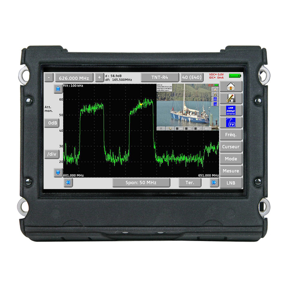
Page 67: Expert Spectrum
– 7871 - 7872 - 7875 - 7876 – 12.6 Expert spectrum All functions of the simplified spectrum are in the expert mode, with additional capabilities. Pay attention to the risks of saturation, use the following formula : Input attenuator = Reference level – 50 dBμV. -
Page 68: Measures
– 7871 - 7872 - 7875 - 7876 – 12.6.1.2 Measures In expert mode, it is possible to display measures. Level: measurement of the signal‟s amplitude at the cursor. Delta : measurement of the amplitude between the two cursors ... -
Page 69: Frequency
– 7871 - 7872 - 7875 - 7876 – 12.6.1.3 Frequency You adjust the following parameters : Fmin : start of frequency sweep Fmax : end of frequency sweep Fcenter : center frequency 12.6.1.4 Cursor Cursor : fast positioning of cursor and peak search : ... -
Page 70: Image And Sound
– 7871 - 7872 - 7875 - 7876 – 13 Image and Sound Pressing the TV zone gives access to the TV function. 13.1 Digital TV The name of the service and its main characteristics are displayed on top right of the screen. -
Page 71: Audio
– 7871 - 7872 - 7875 - 7876 – 13.3 Audio To set the volume, press an adjustment bar shows up: The instrument can decode the following digital sound formats: MPEG-1 L1/L2 Advanced Audio Coding License Via Licensing HE-AAC High Efficiency AAC License Via Licensing ®... -
Page 72: Nit Function
– 7871 - 7872 - 7875 - 7876 – 13.6 NIT function Pressing gives you access to the NIT list: This function allows the display of the « Network Information Table » of the multiplex. The name of the network and some other helpful information are shown in this list. -
Page 73: Record Function Pvr
– 7871 - 7872 - 7875 - 7876 – 13.8 Record function PVR When using function, the instrument will record on USB memory stick the transport stream (audio and video). The stream is the one of the displayed channel. File type is *.TS This function uses the USB-A port, and the port must be set «... -
Page 74: Remote Power Supply / Lnb - Diseqc
– 7871 - 7872 - 7875 - 7876 – 14 Remote power supply / LNB – DiSEqC key gives you access to the remote power supply / LNB-DiSEqC. To start the remote power supply, press the key before Remote power supply: The window allows you to select the remote power supply on terrestrial and/or satellite mode. -
Page 75: Satellite Band
– 7871 - 7872 - 7875 - 7876 – 14.2 Satellite band 14.2.1 Launching Setting the remote power supply to satellite: OFF to turn off the remote power supply under satellite measure ON to turn on the remote power supply under... -
Page 76: Switches
– 7871 - 7872 - 7875 - 7876 – 14.2.2 Switches 2-satellite switch 4-satellite switch * 22 kHz * DiSEqC Committed or Uncommitted * ToneBurst (MiniDiSEqC) *DiSEqC Committed or Uncommitted Uncommitted 16-satellite switch * DiSEqC Committed + Uncommitted... -
Page 77: Positioner
– 7871 - 7872 - 7875 - 7876 – Switch line Uncommitted line Satellite Position Commande DiSEqC Position Commande DiSEqC Pos A Option A + Position A Pos 1 Input 1 Pos B Option A + Position B Pos 1... -
Page 78: Dcss
– 7871 - 7872 - 7875 - 7876 – 14.2.4 DCSS Description: DCSS Digital Channel Stacking system : signal distribution system using frequency transposition. Used in satellite distribution for multiple or single dwelling, with several set top boxes. To give several receptors access to the whole spectrum and all polarizations, you need one coaxial cable per receptor and a suitable installation (multiple LNB, Quattro and multi-switches). - Page 79 – 7871 - 7872 - 7875 - 7876 – The DCSS mode has priority on all other modes: selection polarization, selection OL, switches committed and uncommitted and positioner. 2 Modes : SATCR : Satellite Channel Router, standard EN50494 (or SCD, Unicable, …) Distribution of the satellite signal with only one coaxial cable to 2, 4 or 8 different receptors.
-
Page 80: Influence Of The Dcss On The Spectrum Analyzer
– 7871 - 7872 - 7875 - 7876 – SCD2 (EN50607) : SLOT x : active slot choice CONFIG : access to each slot configuration Slots list, frequencies, switches, PIN codes INITIALISATIONS : 32 predefined slots ... -
Page 81: Constellation
– 7871 - 7872 - 7875 - 7876 – 15 Constellation key gives you access to the CONSTELLATION function. These measures are available if one of these standards is running in the LEVEL MEASUREMENT page. DVB-T/H DVB-T2 ... -
Page 82: Echo / Guard Interval
– 7871 - 7872 - 7875 - 7876 – 16 Echo / Guard interval Available only for DVBT/H, DVB-T2 or DVB-C2 standards. Pressing allows you to access to Echo Guard interval measurement. Signal with echoes and pre-echoes Signal without echo Pressing changes the horizontal scale (distance). - Page 83 – 7871 - 7872 - 7875 - 7876 – Reminder : Remember: In terrestrial TV broadcasting, the received signal on the antenna comes from several possible ways: the echoes. In digital TV DVB-T/H and DVB-T2, these echoes may help or degrade the image according to the time delay between the various signals that reach the antenna.
- Page 84 – 7871 - 7872 - 7875 - 7876 – Relative amplitude in dB and delay in µs (distance in km) from the main signal (0 pulse) can be measured. The yellow line represents the end of the guard interval. Echoes and pre-echoes (pulses) above the yellow line disturb the signal and must be reduced as much as possible.
-
Page 85: Measurement Map
– 7871 - 7872 - 7875 - 7876 – 17 Measurement map To access the MEASUREMENT MAP function, press Home then Measurement map: It is an automatic level and error rate measurement of the setups in the measurement list with labeling of the levels beyond tolerance. -
Page 86: Values Beyond Tolerance
– 7871 - 7872 - 7875 - 7876 – BERi, BERo et PER are generic terms (frequently used) BERi = BER in = inner BER first BER treated by the demodulator (BER channel, CBER, LDPC) BERo = BER out = outer BER... -
Page 87: Graphics
– 7871 - 7872 - 7875 - 7876 – 17.2 Graphics To switch to graphic mode, press Graph. In graphic mode, you can see levels. The measurement is made like for the measurement map. The graph is: for values less than Threshold min ... - Page 88 – 7871 - 7872 - 7875 - 7876 – You may know the name of the setup by pressing directly on the graphic bar you want:...
-
Page 89: Mer/Carrier
– 7871 - 7872 - 7875 - 7876 – 18 MER/Carrier This function is available only for DVB-T/H, DVB-T2 and DVB-C2 standards. Pressing allows you to measure and display MER/ Carrier. The instrument will display MER per carrier and the MER of the whole signal... -
Page 90: Configuration
– 7871 - 7872 - 7875 - 7876 – 19 Configuration For configuration, go to the Home page, then Configuration 19.1 Language You can select your language by pressing the « flag » (below). Press the flag corresponding to your language: 19.2... -
Page 91: Measurement Unit
– 7871 - 7872 - 7875 - 7876 – 19.3 Measurement unit This key allows you to select the measurement unit of the appliance: dBµV: 0 dBµV corresponds to 1 µV dBmV: 0 dBmV corresponds to 1 mV ... -
Page 92: View
– 7871 - 7872 - 7875 - 7876 – When pressing this key, a pull-down menu lists the previously saved files. The first column contains the order number of the file; the second column contains the name of the file; the last column contains the type of file: Measure, Spectrum, Measurement map…... -
Page 93: Save
– 7871 - 7872 - 7875 - 7876 – 19.5.2 Save Save (BMP -> USB) allows you to export the file to the USB stick under BMP format (non-compressed graph); it is useful to transfer graphs to a report in a PC computer. -
Page 94: Delete
– 7871 - 7872 - 7875 - 7876 – Save all (BMP -> USB) records all files from the appliance under BMP format into separated registers: LEVEL for the level measurements MAP for the measurement maps SPECTRUM for the spectrum measurements ... -
Page 95: Password
If the code is right, the appliance will start (there is no limit to the number of trials). It is mandatory to register your instrument and the password to recover a lost password from SEFRAM (please use the template supplied on the CD-ROM) Attention : if you have lost your password please contact the technical support support@sefram.fr... -
Page 96: Active Usb Port
– 7871 - 7872 - 7875 - 7876 – 19.6.4 Active USB port Change it by pressing the key in front of Active USB port: USB A: link to an USB stick (for updating, change of configuration or file output) or to a PC mouse. -
Page 97: Update
– 7871 - 7872 - 7875 - 7876 – You only need to exchange these files between your appliance and the software TR7837 to update your measurement configurations. You can copy these files to the root of an USB memory stick. -
Page 98: Lcd
– 7871 - 7872 - 7875 - 7876 – 19.7 This key allows you to settle the brightness of the screen. You have two possibilities: 50% and 100% (max. brightness). 50% brightness will spare the battery life of the appliance. -
Page 99: Software Update
The update requires an USB stick. To achieve the update: - Download the update file 787X_VX.X zip file on our website (www.sefram.fr) - Insert a USB stick on your PC - Unzip the file onto the root of the memory stick... -
Page 100: Save
– 7871 - 7872 - 7875 - 7876 – 21 Save Pressing opens a window (here, on the Measurement page): In this window, you can save the current measurement parameters from the active list, make a screen shot to a USB stick under BMP format or make a save into internal memory. -
Page 101: Connection Of The Appliance To A Pc
Required configuration These drivers are compatible with the following operating systems: Windows Vista ™, Windows XP ™, Windows Seven ™. For any other operating system, please contact the technical support SEFRAM. Your PC should also have a free USB port. 22.2... -
Page 102: Ethernet Interface
– 7871 - 7872 - 7875 - 7876 – 22.3 Ethernet interface For this kind of connection, no driver installation is required. Connect the appliance to the PC with a crossover ethernet cable (available in option, ref. 298504246 by SEFRAM). - Page 103 – 7871 - 7872 - 7875 - 7876 – Attention: If the PC has already been connected to Ethernet (network, modem…), it is necessary to reboot the PC before connecting your appliance. For the Ethernet connection of your appliance to a computer network, see the following scheme:...
-
Page 104: Multistream Capability
– 7871 - 7872 - 7875 - 7876 – 23 Multistream capability The Multistream is used by specific broadcasters in DVB-S2 (several multiplex in a unique transponder). Atlantic Bird3 5°W uses Multistream for some transponders Example : (Frequency: 12648MHz Vertical, DVB-S2 29500, ISI: ½, Gold code: 121212) -
Page 105: Gps
– 7871 - 7872 - 7875 - 7876 – 24 GPS To access the GPS functions, press Home then 3 functions are available : VIEW function to graphically display all GPS satellites in view LOG function to record the number of GPS satellites used for positioning ... -
Page 106: Log Function
– 7871 - 7872 - 7875 - 7876 – 24.2 LOG function This function allows you to register the number of locked satellites as a function of time. The key below selects the acquisition time (10 mn, 60mn, 8 h, 24 h or 7 days) The «... - Page 107 – 7871 - 7872 - 7875 - 7876 – GPS status : - UTC time - coordinates (latitude, longitude, altitude) of the GPS module - satellites used by the GPS module Measurements : 1 setup or setups 1 to11st from Measurement Map (measurement setup by setup) RF –...
-
Page 108: Recording A File
– 7871 - 7872 - 7875 - 7876 – 24.3.1 Recording a file At the beginning, the appliance is looking of satellites to make good positioning. The “Status GPS” display the GPS coordinates sended by GPS hardware. The RF measurements “Level/BER/MER” or “Measurement Map’ display the associated measurement. -
Page 109: Export And Cartography
– 7871 - 7872 - 7875 - 7876 – The graphical zone represents the display of the current coordinates from the original position. Press this ‘target’ zone to change scale and reset the display. 24.3.2 Export and cartography Après création du fichier*.GPS sur votre appareil, vous pouvez l’exporter sur une clé USB :... - Page 110 – 7871 - 7872 - 7875 - 7876 – Example : using Google Earth After installing Google Earth on your computer, clic 2 times on the file *.KML you have created;: the software show you your records (moves and measurements) : Example : using Google Maps After creating a account Google Maps on your computer, import file *.KML you have created;...
-
Page 111: Optical Power Measurement
– 7871 - 7872 - 7875 - 7876 – 25 Optical Power Measurement To access the Optical Measurement function, press Home then Insert the Optical-USB accessory on the USB connector of the instrument. The configuration must be « USB A »... -
Page 112: Wifi
– 7871 - 7872 - 7875 - 7876 – 26 WIFI To access the Wi-Fi measurement (if fitted inside your appliance), press key Home then Connect the Wi-Fi antenna supplied on the SMA connector. You can measure the RF level received of your Wi-Fi network, or display the list of Wi-Fi networks received by your appliance,with text display (by SSID) and graphical display (Histogram). -
Page 113: Hdmi Connection
– 7871 - 7872 - 7875 - 7876 – 27 HDMI Connection The appliance includes a HDMI "output" connector; Attention: When a HDMI cable is linked to the appliance, the touchscreen is inactive and the screen shuts off. It is advisable to plug a mouse to the USB-A port of the appliance (the USB-A port must be active;... -
Page 114: Displayed Messages
– 7871 - 7872 - 7875 - 7876 – 28 Displayed messages The appliance may display messages while working. 28.1 Alert messages Low battery: the appliance is about to shut off in a few minutes. Confirmation request for an important action. -
Page 115: Error Messages
A message may show up at the bottom of the screen immediately after updating the software. Do not take it into account as far as it does not show up at a second start-up. Else, or for any other problem, contact the SEFRAM technical support: e-mail : support@sefram.fr... -
Page 116: Maintenance
– 7871 - 7872 - 7875 - 7876 – 29 Maintenance This appliance requires some maintenance to meet its requirements and maintain its general characteristics. Consequences Recommended periodicity of Recommended controls use limit BATTERY Reduction of the 200 charge /... - Page 117 100% good functioning pixels in the display zone. They specify a number of possible defective pixels at the surface of the screen. The SEFRAM quality service has preconditioned the mounting of the screen on your instrument to the respect of the acceptance conditions of the manufacturers.
-
Page 118: Technical Specifications
– 7871 - 7872 - 7875 - 7876 – 30 Technical specifications 30.1 Selection Guide 7871 7872 7875 7876 Frequencies 45-2200MHz 5-2200MHz 5-2200MHz 5-2200MHz DVB-T/T2 DVB-C DVB-S/S2, DSS DVB-T2 Lite... -
Page 119: Common Technical Specifications
– 7871 - 7872 - 7875 - 7876 – 30.2 Common technical specifications Technical specifications Terrestrial band Satellite band Frequencies Range 5-900 MHz 900-2200 MHz Resolution measure 50 kHz, display 1 kHz measure 1MHz, display 1MHz Level measurements Dynamic range 20-120 dBµV (30-120 dBµV for 5-45MHz) -
Page 120: Digital Measurements
– 7871 - 7872 - 7875 - 7876 – 30.3 Digital measurements DVB-T/H CBER (before Viterbi BERi) VBER (after Viterbi BERo) Bit Error Rate (BER) UNC (lost packets PER) Noise margin Modulation Error Rate(MER) 5 - 35dB Bandwidth 6MHz, 7 MHz, 8 MHz... - Page 121 – 7871 - 7872 - 7875 - 7876 – DVB-C2 LDPC (BERi) BCH (BERo) Bit Error Rate (BER) FER (frame error PER) Noise margin Modulation Error Rate(MER) 5 - 35dB Symbole rate Bandwidth 6MHz, 8 MHz Mode PLP and data slice, single or multiple...
-
Page 122: Divers
– 7871 - 7872 - 7875 - 7876 – 30.4 Divers Remote supply Terrestrial Satellite 5V/13V/18 V/24V 13/18 V Voltage 500 mA max (300mA for 24V) 500 mA max DiSEqC 1.2 DiSEqC control of dish motor switches committed & uncommitted... -
Page 123: General Specifications
– 7871 - 7872 - 7875 - 7876 – 30.5 General specifications LCD TFT 10 inch color, 16/9, high luminosity backlight 1000 cd/m², 1280x800 dots Display touch screen, capacitive technology, External supply Main adaptor 110/230 VAC, with 5,5mm jack, 15 V 6 A... -
Page 124: V, Dbµv, Dbmv Et Dbm Conversion
– 7871 - 7872 - 7875 - 7876 – 30.7 V, dBµV, dBmV et dBm conversion dBμV (dBmV) is a logarithmic ratio between a measured voltage Ud and a reference voltage Ur. The reference voltage is Ur = 1 μV (1 mV) N = 20 log (Ud/Ur) dBm is a logarithmic ratio between a measured power Pd and a reference power Pr. -
Page 125: Ce Declaration
– 7871 - 7872 - 7875 - 7876 – 31 CE Declaration... - Page 126 – 7871 - 7872 - 7875 - 7876 – SEFRAM 32, rue Edouard MARTEL BP 55 F42009 SAINT-ETIENNE Cedex 2 France Phone : +33 (0)4 77 59 01 01 Fax : +33 (0)4 77 57 23 23 Sales department e-mail : sales@sefram.fr...
Need help?
Do you have a question about the 7871 and is the answer not in the manual?
Questions and answers