Table of Contents
Advertisement
Quick Links
Advertisement
Table of Contents
Troubleshooting

Related Manuals for Thiele Streamfeeder Pro Series


Summary of Contents for Thiele Streamfeeder Pro Series
- Page 1 Pro Series SI-1750 Manual...
- Page 2 Part Number: 00900549 © 2010 Thiele Technologies, Inc. - Streamfeeder. All rights reserved. No part of this publication may be reproduced, photocopied, stored on a retrieval system, or transmitted without the express written consent of Thiele Technologies, Inc. - Streamfeeder.
-
Page 3: Table Of Contents
ontents Safety Information ............ii Specifications ...............v Section 1: About the Machine ............1 Section 2: Preparing for Operation ..........7 Section 3: How to Operate ............22 Section 4: Troubleshooting ............26 Section 5: Inspection and Care ...........28 Section 6: Service and Maintenance Procedures ...... 35 Section 7: I/O Options ..............38 Section 8: Mechanical Components ...........41 Section 9: Electrical Components ..........57 Section 10: Technical Troubleshooting ........68... - Page 4 efore egin Message Conventions DANGER signifies an action or specific equipment area that can result in serious injury or death if proper precautions are not taken. WARNING signifies an action or specific equipment area that can result in personal injury if proper precautions are not taken. CAUTION signifies an action or specific equipment area that can result in equipment damage if proper precautions are not taken.
- Page 5 efore egin Message Conventions Avoid injury. Do not reach around guards. Hazardous voltage. Contact will cause electric shock or burn. Turn off and lock out power before servicing. Moving parts can crush and cut. Keep guards in place. Lock out power before servicing.
- Page 6 afetY Make sure you thoroughly read this section to become familiar with all the safety issues relating to the safe operation of this product. Please read all of the warnings that follow to avoid possible injury. Although every effort has been made to incorporate safety features in the design of this product, there are residual risks that an installer or operator should be aware of to prevent personal injury.
-
Page 7: Specifications
peCifiCations Maximum Product Size: 18 W x 12 L in (457.2 x 304.8 mm) Minimum Product Size: 7.875 W x 3 L in (200 x 76.2 mm) 2 W x 3 L in (50.8 x 76.2 mm) With Small Product Kit: Min/Max Product Thickness: .003-.250 in (.0762-6.35 mm) Belt Speed:... -
Page 8: About The Machine
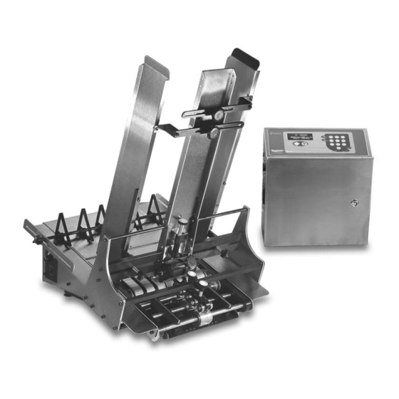
About Your Machine The SI-1750 is designed to separate, singulate, and feed a variety of cut sheets and non-nested products. After product is loaded into the hopper, a simple push of a button starts the feed cycle. Sensors mounted on-line and on the feeder control the start and stop sequence of the feeder cycle. - Page 9 Main Features The machine is entirely powered by a single high-torque stepper mo- tor that runs off of either a 120- or 240-VAC electrical power source. Once the machine is prepared for operation, the power-up and opera- tion of the feeder is relatively easy. But to get the most out of your machine, you should first become familiar with all of the features, including controls and sensors, con- Your feeder may look slightly different than the...
- Page 10 Feature Descriptions of SI-1750 FEEDER Contains the all hardware, drive motor, and belts for singulating and feeding product from a stack. Gate assembly and adjustment Mounted on a gate plate directly above the feed belts, this device provides a curvature to help preshingle stacked product. When properly adjusted, a one-thickness gap is created to help singulate and eject product.
- Page 11 IQuipped Box Features IQuipped Box Feature Descriptions Feature Description AC power cordset connector Cordset plugs into this IEC320 connector to provide feeder with power from 115-VAC or 230-VAC outlet. Power On/Off Toggles AC power On or Off. Fuse holder Contains 2 replaceable GMD3, 3.15-Amp, 5-mm fuses. IMPORTANT: Always make sure power module is replaced exactly as removed.
- Page 12 Control Interface The control interface consists of a keypad and display arrangement which allows you to not only control the operation of the feeder, but it also allows you to monitor the status of the job being run. Control Interface Features Vacuum UP/DOWN Fluorescent...
- Page 13 General The control interface provides you with several different options for monitoring status, entering configuration parameters, and cycling the feeder. To fully understand how the control interface works, you must first understand the Run Display. The default menu from which you will start all control functions is called the Run Display.
-
Page 14: Preparing For Operation
Preparing for Operation Once the SI-1750 is installed, you are then ready to prepare the ma- chine for operation. To do so, you must perform several adjustments with the product you are going to be feeding. And, you must do a test When performing initial adjustments prior to run with this product to verify that it is set correctly before going on- operation, always make sure you turn Off the... - Page 15 Procedure To adjust the gate assembly for proper gap, follow these steps: 1. Slide a single sheet of sample product under the gate assem- bly. You may have to pull up on the adjustment knob to allow the product to be inserted. Excessive lowering of the gate assembly can damage product or lead to premature wear of the 2.
- Page 16 Changing From Review The feeder is shipped to you with a high-tension spring in the gate Factory Set assembly. Certain types of product may demand that you change the High-Tension to gate assembly from a high-tension setting to a low-tension setting (for example, irregular shaped product).
- Page 17 Review STEP 2: The side guides hold the stack of product being fed, and they guide Side Guides Setting the product through the feeder in a straight line of movement. You can adjust the side guides to accommodate different sizes of product. Objective Adjust the side guides so that the product stack maintains uniformity from top to bottom, with no drifting or binding.
- Page 18 To adjust each side guide for proper horizontal spacing, follow these steps: 1. With a small stack of material in the hopper, start by loosening the bottom adjustment knob (counter-clockwise). 2. Grasp the lower part of each guide and move to the recom- mended distance from the product: 1/16 in.
- Page 19 STEP 3: Review The back wedge provides proper lift to the product to help keep it off Back Wedge the table top and feed belts, and it creates the force necessary to push Adjustment product against the gate assembly. By adjusting it back and forth from the gate assembly or pivoting side to side, you can create the lift and force necessary to preshingle product against the curvature of the gate assembly.
- Page 20 Objective Adjust the back wedge for proper support of the product off the table top, without creating any pinch or stress points. Procedure To adjust the back wedge for initial proper positioning, follow these steps: 1. Grasp a handful of product, approximately 2 to 2-1/2 in. (5 to 6 cm) thick, and preshingle the edges with your thumb.
- Page 21 Adjusting Back Wedge for Proper Lift Make sure the edge of the back wedge assembly is parallel with the edge of the product stack. Adjust as required and then tighten knob. 6. Check that individual triangle wedges are evenly spaced to provide enough support to lift the product off the table top and feed belts, without any bowing or twisting.
- Page 22 Now that you are familiar with the basic principles of using a wedge, it is simply a matter of combining these principles to all wedges. The following wedges are covered: • Combination triangle/low-profile • Separate triangle and low-profile • Separate articulating roller and low-profile •...
- Page 23 Separate Triangle and Low-Profile When to use: If moving combination triangle/low-profile wedge assembly back from the gate assembly, bottom of stack still touches table top. This means you need even more mid-range support. Side Setup guidelines: Adjust the triangle wedge the same way that you would the combined triangle/low-profile wedge assembly (see previ- ous page).
- Page 24 Articulating Roller When to use: Effective for very thick and/or ridged product requiring virtually no mid-range support. Setup guidelines: Adjust so that roller edges preshingle the stack against the curvature of gate assembly. Again, make sure edges of Side product do not extend back more than the mid-point of roller. NOTE: With some product that tends to bind together (for example, perforated product), it may be beneficial to separate 4 to 5 sheets of product at the bottom to provide some air space.
- Page 25 STEP 4: Review The hold-down assembly consists of several adjustable rollers which Hold-Down Setting rest on top of the product as it exits the gate assembly area. With the correct amount of pressure applied to the product, the discharge belt will have the proper amount of contact and friction needed to pull product away from the gate assembly area.
- Page 26 Often after you adjust the first roller you have to go back and readjust the second roller to make sure that the drag is correct. Turning Knobs Counter-Clockwise to Insert Product Turning Knob “A” Clockwise to Get Slight Drag STEP 5: Review The photo sensor labeled Flight is mounted on the line to detect a Photo Sensor...
- Page 27 Procedure To adjust the Sheet photo sensor for proper positioning, follow these steps: Standard photo sensors shipped from the factory 1. Aim and align the photo sensor straight toward (perpendicular are two diffuse reflective detectors. No adjustment to) the product. If the photo sensor is at an angle, the light will for gain is required or necessary.
- Page 28 Manual Test To Now that you have made all the necessary adjustments for operation, it is recommended that you verify the singulation and separation of Verify product through the gate assembly area. Before you power-up and run your machine with a full hopper, manually feed several sheets of product through the gate assembly area.
-
Page 29: How To Operate
How to Operate Operational Successful power-up and operation of the feeder is assured if you ap- ply each of following sets of procedures where needed: Sequences • Loading product • Quick setup/cycle sequence • Accessing the menus for setup • Starting a cycle •... - Page 30 Quick Setup/Cycle If the feeder is prepared for operation and you want get the feeder started in the quickest way possible, use the following sequence: Sequence 1. Turn power 2. Press any key to advance to “Suspended” screen. Even though the Run Display is factory-set for 3.
- Page 31 Accessing the If you wish to configure all the parameters of your machine via the menus, use the following sequence for accessing the menus: Menus for Setup 1. Turn power 2. Press any key to advance to “Suspended” screen. 3. Press MENU key. Menus can be customized to suit your changing 4.
- Page 32 Stopping the Feeder The feeder can be stopped either manually or automatically. Pressing the STOP key will stop feed cycles and return the feeder to the “Suspended” status. When a product fails to be staged in a preset amount of time, the feeder will automatically timeout or stop.
-
Page 33: Troubleshooting
Troubleshooting This table will provide you with quick solutions to the more common day-to-day problems you may encounter. Quick-Look Troubleshooting Problem Cause Solution No AC power to 1. On/Off switch in “Off” (or “0” position). Check that switch pressed to “On” feeder (or “—”... - Page 34 Quick-Look Troubleshooting (continued) Si-1750 M erieS anual...
-
Page 35: Inspection And Care
Inspection and Care Please read this Section to learn how to: • Visually inspect your machine to detect part problems which may require adjustment or replacement. When performing initial adjustments prior to • Periodically care for your machine to prevent any operational prob- operation, always make sure you turn Off the lems. - Page 36 Visual Inspection Ensuring Proper Feed and Discharge Belt Tracking (continued) Check for visual sign of: • Stretching. • Improper roller adjustment. Ensuring Proper Timing and Drive Belt Tracking Check for visual signs of: • Misaligned timing pulleys. Si-1750 M erieS anual...
- Page 37 Visual Inspection Checking for Gate Assembly Wear Check for visual signs of wear: (continued) • Bar gate: Angled wedge begins to flatten excessively. • Standard O-ring or advancing O-ring (if applicable): Flat areas along the O-rings. See “Preventative Care” to follow. Si-1750 M erieS anual...
- Page 38 Visual Inspection Replacing Worn Angled Wedge (continued) To replace a worn angled wedge: 1. Turn Off feeder and remove power cord from outlet. 2. Remove gate assembly from gate plate. 3. Use a pliers to grip and remove angled wedge. 4.
- Page 39 Preventative Care Cleaning Feed and Discharge Belts To clean feed and discharge belts: 1. Turn Off feeder and remove power cord from outlet. Use only isopropyl alcohol (98% concentration). 2. Remove gate assembly from gate plate for easier access to Other solvents can cause belts to wear belts.
- Page 40 Preventative Care Cleaning Gate Assembly Use only isopropyl alcohol (minimum 98% concentration). Do not (continued) use any other types of solvents. They can cause premature wear of the belts, or even total breakdown of the material. To clean gate assemblies: 1.
- Page 41 Cleaning Controller Box Visually check the fan ventilation area of the controller box for exces- sive dust or grime buildup that might inhibit air movement. For more Turn off feeder and disconnect from main information, consult with a qualified technician. power source before cleaning.
-
Page 42: Service And Maintenance Procedures
Service and Maintenance Procedures Si-1750 M erieS anual... - Page 43 Si-1750 M erieS anual...
- Page 44 Si-1750 M erieS anual...
-
Page 45: I/O Options
I/O Options Si-1750 M erieS anual... - Page 46 Si-1750 M erieS anual...
- Page 47 Si-1750 M erieS anual...
-
Page 48: 8 Mechanical Components
8 Mechanical Components Item # Description Gate Holder Plate Assembly Right Side Plate Assembly Left Side Plate Assembly Table Top Assembly Tall Insert Guide Assembly Base Plate Assembly Hold Down Assembly Gate Cylinder Assembly Sheet Sensor Assembly Grooved Gum Carriage Assembly I-Quipped Box Si-1750 M erieS... - Page 49 Si-1750 M erieS anual...
- Page 50 S-1750IJ Gate Holder Plate Assembly Item# Qty. Part# Description 235-00-001 Gate Holder Plate 418-55-017 Insert Guide Stabilizing Bracket 418-55-010 Gate Support Shaft 418-55-014 Left Hand Side Guide Bracket 418-55-013 Right Hand Side Guide Bracket 418-55-016 Gate Support Bar 2315 SHCS 10-32 x 1/2" 2310 SHCS 10-32 x 3/8"...
- Page 51 S-1750IJ Right Side Plate Assembly Item# Qty. Part# Description 2310 SHCS 10-32 x 3/8" 418-55-200 Right Hand Side Plate 2110 Nylock Nut 10-32 235-60-202 Carriage Holder Si-1750 M erieS anual...
- Page 52 S-1750IJ Left Side Plate Assembly Item# Qty. Part# Description 418-55-201 Left Hand Side Plate 2110 Nylock Nut 10-32 2310 SHCS 10-32 x 3/8" 235-60-203 Carriage Holder Si-1750 M erieS anual...
- Page 53 S-1750IJ Table Top Assembly Item# Qty. Part# Description 435-55-204 Table Top 535-00-014 On/Off Switch 2305 BHCS 10-32 x 3/8" 535-00-105 Filter Screen 435-55-203 Timing Belt Acess Cover 235-00-064 USA Label 235-00-066 Nameplate 1101 Blind Rivet 535-00-023 Legend "Power" Items Not Shown On Drawing Si-1750 M erieS anual...
- Page 54 S-1750IJ Tall Insert Guide Assembly Qty. Part# Description Item# 235-00-006 Tall Insert Guide 235-00-093 Large Thumb Screw 2390 SHCS 1/4-20 x 1" 335-00-018 Sensor Extension Spacer 435-00-150 Adjusting Stabilizer Bracket 435-00-151 Center Stabilizer Mounting Bracket 435-00-152 Stabilizer Side Guide Spacer 435-60-208 Left Side Guide Extension 435-60-209...
- Page 55 S-1750IJ Base Plate Assembly Item# Qty. Part# Description 435-50-007 Base Plate 2310 SHCS 10-32 x 3/8" 535-11-005 2 Meter Power Cord Si-1750 M erieS anual...
- Page 56 *Part exists in diagram for reference only and is not included with this assembly. Must be ordered separately. 5 AXLE HOLD DOWN ASSEMBLY #43511310 DIAGRAM PART NUMBER DESCRIPTION NUMBER Bearing Holder Shaft 43560008 Bearing Ball R6 23500095 Ring Grip 3/8 Waldes 00001110 Clip E 3/8 Waldes 00001150...
- Page 57 Si-1750 M erieS anual...
- Page 58 GROOVED GUM RUBBER BELT CARRIAGE ASSEMBLY #43533485 ITEM NAME 43500096 DRIVE BELT 170 X L037 43555047 IDLER SHAFT 43555147 IDLER SHAFT 43555205 3-4 IN DRIVE SHAFT 43555211 DRIVE SHAFT 43560097 PULLEY 16T 43560098 PULLEY 24T 44485001 MANIFOLD 44485003 VACUUM BELT 23511270 BELT SUPPORT ROLLER 23500094 BEARING R8-2RS 23560208 CROWN DRV ROLLER...
- Page 59 Si-1750 M erieS anual...
- Page 60 IQUIPPED BOX WITH I/O ASSEMBLY #68311050 Si-1750 M erieS anual...
- Page 61 IQUIPPED BOX WITH I/0 ASSEMBLY #68311050 DIAGRAM PART NUMBER DESCRIPTION NUMBER 11-1 Insert 7mm Square 44683022 11-2 Cam Latch Lock 44683021 11-3 44” Gasket 44683028 11-4 Bracket Display Mounting 44683002 11-5 Display VFD w/Connector Header Pin 53511605 11-6 Board Keypad Decoder 53500605 *11-7 Board Relay I/O...
- Page 62 ASSEMBLY #68311050 Si-1750 M erieS anual...
- Page 63 Break-Out Board No. Connector (to) Label Wires at End (from) Color This End Signal Pin B1 Label “9” DC Ground Pin B2 Label “10” DC Ground Pin B3 Label “11” +12V DC Pin B4 Label “12” +12V DC Pin B5 Label “13”...
-
Page 64: Electrical Components
Electrical Components Supplied with Tower Lamp Option Low Stack J5-1 + 12V DC J5-2 Low Stack Signal J5-3 BLU & WHT DC Ground Sheet J2-1 + 12V DC J2-2 Sheet Signal J2-3 DC Ground J2-4 Inverted Sheet Signal Interlock J3-1 + 12V DC J3-2 Interlock Signal... - Page 65 External IQuipped Box Si-1750 M erieS anual...
- Page 66 External IQuipped Box FR AME/ HOUSING END (FROM) AWG COLOR (TO) SIGNAL Pin B14 J11-1 Tower Lamp - Green Pin B13 J11-2 Tower Lamp - Amber Pin B12 J11-3 Tower lamp - Red n.c. J11-4 n.c. J11-5 Pin B3 J5-1 +12V DC Pin B5 J5-2...
- Page 67 CPU Detail 44649014 Si-1750 M erieS anual...
- Page 68 Power Supply 44649033 Si-1750 M erieS anual...
- Page 69 44649034 Si-1750 M erieS anual...
- Page 70 Motherboard Si-1750 M erieS anual...
- Page 71 Wiring Diagram: 6-Lead Stepper Motor Si-1750 M erieS anual...
- Page 72 Stepper Motor Drive Boards #44649030 and #53500467 Si-1750 M erieS anual...
- Page 73 Transformer 53511701 Si-1750 M erieS anual...
- Page 74 I/O Board 44649128 Si-1750 M erieS anual...
-
Page 75: Section 10: Technical Troubleshooting
Technical Troubleshooting General Troubleshooting The “drive” consists of the AC power supply (transformer), the stepper motor drive board, and the motor. The “controls” consist of the DC power Terms supply, the CPU board, the display/keypad decoder boards, the keypad, any ribbon cables and wiring harnesses, the sensors, the motherboard, and the relay I/O. - Page 76 Quick-Look Troubleshooting (continued) Problem Solution 3. Reconnect AC loads one item at a time while alternately applying power between new Fuses blow on power up connections. Connect each load as follows one at a time to determine the faulty part: (continued) Connect the transformer primary leads to the AC input module.
- Page 77 Quick-Look Troubleshooting (continued) Problem Solution Display does not 1. Check green “heartbeat” LED located on the top of the CPU board. It will blink at function properly regular intervals under normal operation when the feeder is in “Ready” or “Suspended” mode.
- Page 78 Quick-Look Troubleshooting (continued) Problem Solution 3. Check connection to the CPU board at 3-pin connector J6. Note: Pin 1 is 12VDC, pin “FEEDER TIMED OUT” 2 is the signal input pin, and pin 3 is DC ground. Pins 1 and 3 give life to the sensor, message displayed and pin two requires 12VDC to be applied to it when a “sheet”...
- Page 79 Quick-Look Troubleshooting (continued) Problem Solution Jumper pins 1 and 2 on CPU board connector J5. This will simulate the output of Flight photo sensor the “flight” sensor and should trigger a cycle. does not trigger feeder If steps 2a and 2b produce positive results as described above, all three pins of (continued) J5 on the CPU board are good.
- Page 80 Quick-Look Troubleshooting (continued) Problem Solution Using a digital multimeter or an oscilloscope, measure the amplitude of the Motor does not run, pulse train and verify it is at least 2.5VDC. is noisy, makes a If pulse tests good, replace the stepper motor drive board. If the pulse tests “growling”...
- Page 81 DIaGNOSTICS / TESTS Diagnostics / Tests Problem Solution Refer to the wiring diagram of the 6-lead DC Stepping Motor found elsewhere in this Testing motors manual. The motors have two windings, three leads associated with each winding, for a total of six leads.
- Page 82 Diagnostics / Tests (continued) Problem Solution Testing the transformer The following assumes all crimp-on connectors are properly connected to the transformer (continued) wires and are making contact with them, or are NOT crimped onto the insulation prevent- ing a good electrical connection to the individual wires of the transformer. 1.
-
Page 83: Section 11: Menu Guide
Si-1750 M erieS anual... - Page 84 Menu Guide The control interface consists of a keypad and display arrangement Control Interface which allows you to not only control the operation of the Pro Series feeder/dispenser, but it also allows you to monitor the status of the job being run.
- Page 85 General The control interface provides you with several different options for monitoring status, entering configuration parameters, and cycling the feeder. Depending upon your particular needs, the control interface can pro- vide you with either one-shot control or batch control. Your machine will be set up for one or the other at the time of shipment.
- Page 86 Pro Series Operation Menus Objective This document provides an overview of technician-level menu pro- gramming and system configuration of the Pro Series version. This Pro Series version of code was designed to restrict access to Gaining Access Beyond certain types of non-operational menus and system configurations. As you navigate through the factory-default menus you will notice a the Passcode Screen PASSCODE screen.
- Page 87 Pro Series System Menus (continued) 1.16 B ERIES UIPPED ONTROLS OFTWARE ENUS ERSION ATCH OUNT 1 SPEED 10 MISS Values = X (1% - 100%) Output Duration: Xms Feeder pause Input = 0 (Latched) Input = 20 - 999ms 2 SIZE Consecutive misses: X Enter batch size = X (1 - 9999) 11 REPORT...
- Page 88 Pro Series System MENU 1: SPEED Allows you to set the desired speed value from 1 to 100 percent (This Menus (continued) is the maximum speed when Speed Following = Off; See Menu 14: CONVR). To change the speed value (If Speed Following = Off): 1.
- Page 89 Pro Series System MENU 5: DELAY (continued) Menus (continued) 3. Use the Up/Down arrow keys or Numeric keypad to reach your desired time delay. 4. Press the Enter key to save new time. OR Press the MENU key to restore old time and return to “Run Display.” MENU 6: TRIG To select a Flight Trigger method: 1.
- Page 90 Pro Series System MENU 7: ACCEL Allows you to set the feeder acceleration rate at Fast, Normal or Slow. Menus (continued) To set or change: 1. Use the Up/Down Arrow keys to position cursor arrow at your desired acceleration. 2. Press the Enter key to select and save. A darkened circle indi- cates the option has been selected.
- Page 91 Pro Series System MENU 8: DOUBLE (continued) b. Input Active: (High) or Low Menus (continued) 1. Press the Up/Down arrow keys to position the cursor arrow by “Input Active: High.” 2. Press the Enter key to change Input Active state from High to Low (or vice versa).
- Page 92 Pro Series System MENU 9: OPTS (continued) Menus (continued) 2. Use the Up/Down Arrow keys to position the cursor arrow by the item you wish to change. 3. Press the Enter key repeatedly to change the option to the de- sired parameter.
- Page 93 Pro Series System MENU 10: MISS Menus (continued) If your feeder is equipped with the Systems Interface I/O option, this menu will allow you to activate the Miss Output and configure its operation as follows: 1. Output: OFF/ON 2. Duration: 20mS to 999mS (Default is 100mS)/0 LATCHED 3.
- Page 94 Pro Series System MENU 10: MISS (continued) Menus (continued) 4. Press Enter to save new value. Press Menu to restore old value and return to “Run Display.” To pause the feeder if a Miss occurs: 1. Use the Up/Down Arrow keys to position the cursor arrow by Feeder Pause.
- Page 95 Pro Series System MENU 12: DECEL (continued) Menus (continued) 3. Use the Up/Down Arrow keys or numeric keypad to enter your desired speed (1 to 100 percent). 4. Press the Enter key to save selected input. Press the MENU key to restore old speed and return to “Run Display.”...
- Page 96 MENU 14: CONVR Pro Series System Menus (continued) Theory of operation: The speed following package allows the use of an encoder to provide an exact representation of the speed of an attached conveyor. Once Speed Following the feeder knows the speed of the conveyor, the feeder can automati- Pre-installation cally adjust the speed of the feeder.
- Page 97 Pro Series System MENU 14: CONVR (continued) Menus (continued) SETUP (continued) Speed Following 6) The following table is a sample of how the encoder speeds (RPM), Pre-installation adjust value (ADJ) and conveyor speeds (FPM) are related. Instructions ADJ=2 ADJ=5 ADJ =10 ADJ =20 ADJ =30 ADJ =40...
- Page 98 Pro Series System MENU 14: CONVR (continued) Menus (continued) Adjusts the calculation of conveyor speed by changing the “Conveyor speed adjust value” setting. The “Conveyor speed adjust value” can be set from 1 to 100. Increasing the value will increase the measured conveyor speed.
- Page 99 Pro Series System MENU 15: COM Menus (continued) You may connect the feeder Communication Port to an RS-232 termi- nal to observe current feeder values stored in memory. Bold numbers shown are factory defaults. 1. Com0 Baud: 2400, 9600, 19200, 28800, 38400, 57600, or 115200.
- Page 100 Pro Series System MENU 15: COM (continued) Menus (continued) To set up a Communication Port for a new baud rate: 1. Use the Up/Down Arrow keys to position the cursor arrow by the Communication Port that you wish to set up. 2.
- Page 101 Pro Series System MENU 16: DIAG (continued) Menus (continued) 3. Assert the Trigger Input. This input most commonly has a photo electric sensor connected to it and is referred to as the “Flight” sensor. 4. Observe the “Testing: ????????” line of the display. a) If the input is operating correctly, the question marks will be replaced with the word “Trigger”...
- Page 102 Pro Series System SYSTEM CONFIG Menus (continued) The System Configuration is broken into trhee main sections: 1. Run Screen 2. Change Passcode 3. Menu Security To change the information that is currently displayed on your “Run Screen”: 1. Use the Up/Down arrow keys to position cursor by “Run Screen.”...
- Page 103 Pro Series System SYSTEM CONFIG (continued) Menus (continued) To change your system menus passcode: 1. Use the Up/Down Arrow keys to position cursor arrow by “Change Passcode.” 2. Press the Enter key to select. 3. Use the numeric keypad to enter your current passcode. 4.
- Page 104 Small Product Narrowing Kit Diagram Part Number Description Number Side Guide Extension Bracket 33500040 SHCS 1/4 –20 x 1 1/2 00002396 Side Guide Mounting Spacer 43500158 Items 4 and 5 are S-1750/S-1750IJ components and not included in Side Guide Narrowing Kit. Inclusion is for instruction purposes only.
- Page 106 © 2010 Thiele Technologies, Inc. - Streamfeeder Printed in the USA.
Need help?
Do you have a question about the Streamfeeder Pro Series and is the answer not in the manual?
Questions and answers