H3C S12500X-AF Series Hardware Reference Manual
Hide thumbs
Also See for S12500X-AF Series:
- Configuration manual (224 pages) ,
- Installation manual (136 pages) ,
- Quick start manual (42 pages)

Related Manuals for H3C S12500X-AF Series


Summary of Contents for H3C S12500X-AF Series
- Page 1 H3C S12500X-AF Switch Series Hardware Reference New H3C Technologies Co., Ltd. http://www.h3c.com Document version: 6W102-20201222...
- Page 2 The information in this document is subject to change without notice. All contents in this document, including statements, information, and recommendations, are believed to be accurate, but they are presented without warranty of any kind, express or implied. H3C shall not be liable for technical or editorial errors or omissions contained herein.
- Page 3 Preface This document describes the hardware information of H3C S12500X-AF switch series, including chassis views and technical specifications, FRUs and compatibility matrixes, LEDs, and cables. This preface includes the following topics about the documentation: • Audience. • Conventions. • Documentation feedback.
- Page 4 Symbols Convention Description An alert that calls attention to important information that if not understood or followed WARNING! can result in personal injury. An alert that calls attention to important information that if not understood or followed CAUTION: can result in data loss, data corruption, or damage to hardware or software. An alert that calls attention to essential information.
- Page 5 Documentation feedback You can e-mail your comments about product documentation to info@h3c.com. We appreciate your comments.
-
Page 6: Table Of Contents
Contents Chassis views and technical specifications ···················································· 1 Chassis views ···················································································································································· 1 Chassis components ·········································································································································· 3 Technical specifications ····································································································································· 7 Weights and dimensions ···························································································································· 7 Module power consumption and system power consumption ········································································· 11 Card power consumption ························································································································· 11 Fan tray power consumption ···················································································································· 13 System power consumption ·····················································································································... -
Page 7: Chassis Views And Technical Specifications
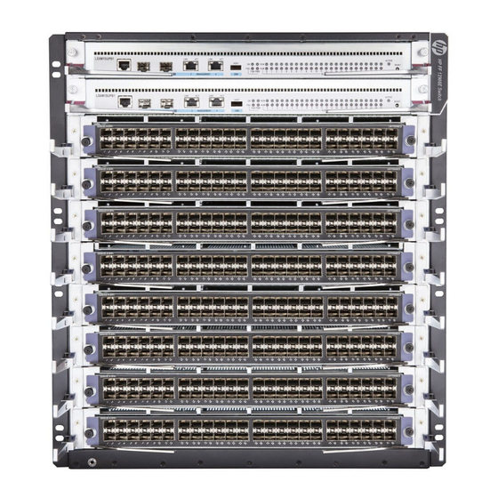
Chassis views and technical specifications The H3C S12500X-AF Switch Series is a set of core switches designed for cloud computing data centers. It uses the advanced CLOS orthogonal switching fabric architecture to deliver the industry-leading switching performance, highest port density, richest cloud computing features, and highest availability. - Page 8 Figure 2 S12512X-AF Figure 3 S12508X-AF Figure 4 S12504X-AF...
-
Page 9: Chassis Components
Figure 5 S12502X-AF Figure 6 S12501X-AF Chassis components The device has an MPU section, service module section, power module section, fan tray section, and fabric module section. The following figure uses the S12516X-AF for illustration. - Page 10 Figure 7 Front and rear views of the S12516X-AF switch (1) MPU section (2) LPU section (3) Power module section (4) Fan tray section (5) Switching fabric module section Table 1 Description for the switch sections Section Location identification Installation description Pink color is used for you to identify the MPU installation location.
- Page 11 Section Location identification Installation description MPUs are also pink marked to suggest the corresponding installation location. NOTE: The MPU section of an S12504X-AF switch is located below the LPU section. • S12516X-AF switch—16 LPU slots. The ejector lever pillow blocks on •...
- Page 12 Section Location identification Installation description installation. For an LSXM1TGS24FX1 LPU to start up correctly, install a minimum of one switching fabric modules in the three lowest-numbered switching fabric module slots. • To use an LSXM1TGS48C2HB1, LSXM1TGS48HB1, LSXM1TGS48HF1, LSXM1CGQ6QGHB1, LSXM1CGQ6QGHF1, or LSXM1TGS24QGMODHB1 LPU, the three highest-numbered switching fabric module slots take precedence over other slots for module...
-
Page 13: Technical Specifications
Technical specifications Weights and dimensions The switch uses modular design. Its weight includes the chassis (mounting brackets and filler panels included) and its FRUs. Table 3 Chassis weights and dimensions Model Weight Height Width Depth S12516X-AF 86.1 kg (189.81 lb) 931 mm (36.65 in)/21 RU 440 mm (17.32 in) 857 mm (33.74 in) - Page 14 Model Weight Height Width Depth LSXM1SFH16E1 9.7 kg (21.38 lb) 39.8 mm (1.57 in) 853.0 mm (33.58 in) 278.4 mm (10.96 in) LSXM1SFH12C1 6.4 kg (14.11 lb) 39.8 mm (1.57 in) 675.2 mm (26.58 in) 278.4 mm (10.96 in) LSXM1SFH12D1 7.5 kg (16.53 lb) 39.8 mm (1.57 in) 675.2 mm (26.58 in)
- Page 15 Model Weight Height Width Depth LSXM1QGS48HB1 9.2 kg (20.28 lb) 50.0 mm (1.97 in) 432.6 mm (17.03 in) 519.8 mm (20.46 in) LSXM1QGS36HB1 7.8 kg (17.20 lb) 50.0 mm (1.97 in) 432.6 mm (17.03 in) 519.8 mm (20.46 in) LSXM1QGS24HB1 7.6 kg (16.75 lb) 50.0 mm (1.97 in) 432.6 mm (17.03 in)
- Page 16 Table 6 Power module weights and dimensions Model Weight Height Width Depth PSR1800-56A 1.6 kg (3.52 lb) 41.0 mm (1.61 in) 82.6 mm (3.25 in) 297.7 mm (11.72 in) PSR1800-56D 2.0 kg (4.40 lb) 41.0 mm (1.61 in) 82.6 mm (3.25 in) 297.7 mm (11.72 in) PSR2400-54A 1.9 kg (4.19 lb)
-
Page 17: Module Power Consumption And System Power Consumption
Module power consumption and system power consumption Card power consumption The power consumption of the cards depends on the card model and state. Table 10 shows the power consumption for different card models. • The static power consumption of a card refers to the power consumed by the card when the card is running but all ports on the card are down and when no transceiver module is available on the optical interface of the card. - Page 18 Minimum static power Maximum dynamic power Model consumption consumption LSXM1SFH04D1 86 W 140 W LSXM1SFT16E1 419 W 691 W LSXM2SFT08E1 265 W 446 W LSXM1QGS24FE1 310 W 505 W LSXM1TGS48FE1 160 W 260 W LSXM1TGS48FX1 160 W 275 W LSXM1TGS24FX1 86 W 145 W LSXM1TGW48FX1...
-
Page 19: Fan Tray Power Consumption
Minimum static power Maximum dynamic power Model consumption consumption LSXM2CGQ18QGHB2 256 W 525 W LSXM1CGQ48KB1 395 W 765 W LSXM1CDQ24KB1 469 W 1020 W IMPORTANT: High-performance fan trays are required when the switch uses the LSXM1CGQ18QGHF1, LSXM1CGQ48HB1, LSXM1CGQ36HB1, LSXM1CGQ36HF1, LSXM1CGQ36TD1, LSXM1CGQ48KB1, or LSXM1CDQ24KB1 cards. -
Page 20: Heat Dissipation
90%. Heat dissipation/hour of the switch is 0.9 × (total power consumption of the cards plus power consumption of the fan tray)/0.9 × 3.4121. For the power consumption of the cards and fan trays of the H3C S12500X-AF switches, see "Module power consumption and system power consumption."... -
Page 21: Chassis Ordering Information
The sound pressure levels are measured according to the method specified in ISO 7779 at the bystander position. Chassis ordering information To purchase an S12500X-AF chassis, contact the sales agent or H3C sales personnel. Table 13 S12500X-AF chassis ordering information Product code... - Page 22 Contents FRUs and compatibility matrixes···································································· 1 MPUs ································································································································································· 1 Cloud supervisor engine unit······························································································································ 3 Interface module adapter ··································································································································· 4 LPUs ·································································································································································· 4 S12500X-AF LPUs ····································································································································· 4 S12500-X LPUs ········································································································································· 9 Subcards ·························································································································································· 11 Switching fabric modules ································································································································· 11 Switching fabric module slot filler panel ··········································································································· 12 Slide rails··························································································································································...
-
Page 23: Frus And Compatibility Matrixes
FRUs and compatibility matrixes For transceiver modules or cables compatible with the cards, see H3C S12500X-AF Switch Series Cards and Transceiver Modules Compatibility Matrixes. MPUs The switch uses an MPU for control and management. You can install one MPU or two MPUs for redundancy on the switch. - Page 24 LSXM1SUPB1/LSXM1SUP Item LSXM1SUPA1 LSXM1SUP02B1 04B1 • Console port: ≤ • Console port: ≤ 115200 • Console port: ≤ 115200 115200 bps (default: bps (default: 9600 bps) bps (default: 9600 bps) 9600 bps) Transmissi • • SFP port: 1000 Mbps SFP port: 1000 Mbps •...
-
Page 25: Cloud Supervisor Engine Unit
• 1 × USB port (USB 3.0, host port) • 1 × 1PPS/ToD time synchronization port • 2 × SMB clock input ports • 2 × SMB clock output ports • Console port: 9600 bps (default) to 115200 bps • 10/100/1000BASE-T port: 10/100/1000 Mbps Transmission rate •... -
Page 26: Interface Module Adapter
Item Specification • 2 × GE SFP management port for the switching control units • 2 × 10/100/1000BASE-T management port for the switching control units • 1 × USB port for the X86 server unit • 1 × BMC port for the X86 server unit Ports •... - Page 27 Table 6 S12500X-AF Type F LPU specifications Port Port Available transceiver LPU model Description Connector quantity speed modules • QSFP+ transceiver 36-port 40GE module • LSXM3QGS3 QSFP+ Ethernet • QSFP+ copper cable 40 Gbps • 6FX1 optical interface • QSFP+ to SFP+ card copper cable 12-port 100GE...
- Page 28 Port Available transceiver Description Connector Port speed model quantity modules 18-port 100GE • QSFP28 transceiver QSFP28 module • QSFP28 Ethernet • QSFP28 copper port: optical cable 100/40 interface/36-p • LSXM1CGQ • Gbps QSFP28 fiber cable ort 40GE • 18QGHB1 • •...
- Page 29 Port Available transceiver Description Connector Port speed model quantity modules • QSFP28 transceiver module • QSFP28 copper 48-port 100GE cable QSFP28 LSXM1CGQ • QSFP28 fiber cable Ethernet 100/40 Gbps 48HB1 • optical QSFP+ transceiver interface card module • QSFP+ copper cable •...
- Page 30 Port Available transceiver Description Connector Port speed model quantity modules 24-port 10GE SFP+ port: SFP+ Ethernet 26 fixed • SFP+ transceiver optical ports and module interface + interface • SFP+ copper cable 4-port 100G module LSXM1TGS • QSFP28 port (see QSFP28 port: 24CGMOD 100/10 Gbps...
-
Page 31: S12500-X Lpus
Table 9 S12500X-AF Type K LPU specifications Port Available transceiver Description Connector Port speed model quantity modules • QSFP28 transceiver module • 48-port 100GE QSFP28 copper QSFP28 cable LSXM1CGQ Ethernet • QSFP28 fiber cable 100/40 Gbps 48KB1 optical • QSFP+ transceiver interface module module... - Page 32 Available Port Description Connector Port speed transceiver model quantity modules • 10GE SFP+ transceiver module 24-port 10GE • 10GE SFP+ LSXM1TGS SFP+ Ethernet 10/1 Gbps copper cable 24FX1 optical interface • card GE SFP transceiver module • • LAN mode: 10GE SFP+ 48-port 10-GE 10.31 Gbps...
-
Page 33: Subcards
Subcards Table 11 describes the subcards available for the LSXM1TGS24QGMODHB1 LPU. Table 11 Subcards available for the LSXM1TGS24QGMODHB1 LPU Subcard model Description Port type and quantity LSWM18QC 8-port QSFP+ interface card 8 × QSFP+ ports 24-port SFP+ and 2-port QSFP+ LSWM124XG2Q 24 ×... -
Page 34: Switching Fabric Module Slot Filler Panel
• Type H switching fabric modules must be used with Type H LPUs. • Type T switching fabric modules must be used with Type T LPUs. • Type K switching fabric modules must be used with Type K LPUs. Table 13 Type F switching fabric module ordering guide Switch model Available switching fabric modules •... -
Page 35: Slide Rails
Item Quantity Switching fabric module slot filler panel for the S12512X-AF switch 0 to 4 Switching fabric module slot filler panel for the S12508X-AF switch 0 to 4 Switching fabric module slot filler panel for the S12504X-AF switch 0 to 4 Slide rails The switches (except the S12501X-AF) are not shipped with slide rails. - Page 36 The switch supports N+N (two power supply systems) or N+1 (one power supply system) power redundancy. You can install appropriate number of power modules according to the power supply mode and system consumption. Make sure the total maximum output power of the installed power modules is greater than the system power consumption.
- Page 37 Item Specifications Maximum output current 44.5 A • 1200 W @ 110 VAC Maximum output power • 2400 W @ 220 VAC Dimensions (H × W × D) 41 × 100 × 332 mm (1.61 × 3.94 × 13.07 in) Operating temperature –10°C to +50°C (–14°F to +122°F) Ambient temperature...
-
Page 38: Fan Trays
Item Specifications Dimensions (H × W × D) 41 × 100 × 332 mm (1.61 × 3.94 × 13.07 in) Operating temperature –10°C to +50°C (–14°F to +122°F) Ambient temperature Storage temperature –40°C to +70°C (–40°F to +158°F) Table 25 PSR3000-54AHD power module specifications Item Specifications Rate input voltage... -
Page 39: Dc Power Cords
Make sure you select a compliant power cord for a power supply. For more information about AC power cords, see H3C Power Cords & Cables User Guide. Chassis component ordering information To purchase chassis components, contact the sales agent or H3C sales personnel. - Page 40 LSXM1SFF08B1 Switching fabric module for S12504X-AF, Type F (Class 0231A3C3 LSXM1SFF04B1 0231A4PW LSXM1SFH16C1 H3C S12516X-AF fabric module, Type H (Class C+) 0231A5CG LSXM2SFH16C1 H3C S12516X-AF fabric module, Type H (Class C) 0231A4QG LSXM1SFH16E1 H3C S12516X-AF fabric module, Type H (Class E)
- Page 41 LSXM2TGS48FX1 interface module (SFP+, LC) (FX) H3C S12500-X 24-port 40GBASE Ethernet optical 0231A4P0 LSXM2QGS24FX1 interface module (QSFP+) (FX) H3C S12500-X 48-port 10GBASE Ethernet WAN optical 0231A4NS LSXM1TGW48FX1 interface module (SFP+, LC) (FX) H3C S12500X-AF 12-port 100GBASE Ethernet optical 0231A3A2 LSXM1CGP12FX1...
- Page 42 Product code Product name Description optical interface module (QSFP28) (HB) H3C S12500X-AF 36-port 100GBASE Ethernet optical 0231A4PR LSXM1CGQ36HF1 interface module (QSFP28) (HF) H3C S12500X-AF 18-port 100GBASE Ethernet optical 0231A4QE LSXM1CGQ18QGHF1 interface (QSFP28)/36-port 40GBASE Ethernet optical interface module (QSFP+) (HF) H3C S12500X-AF 48-port 10GBASE Ethernet optical...
- Page 43 08 fabric blank filler panel 0231A3RM LSXM1BFP04A 04 fabric blank filler panel Slide rails 0231A4EK LSXM1BSR 1U bottom-support rails, 630mm to 900mm 0231A0PL LSTM2KSGD0 Slide rail accessories, 500mm to 800mm 0231A2VL LSVM1BSR10 H3C S9810 bottom support rails, 630mm to 900mm...
- Page 44 Contents LEDs ·············································································································· 1 MPU LEDs ························································································································································· 1 Management Ethernet port LEDs··············································································································· 2 Fan tray status LEDs ·································································································································· 3 Power module status LEDs ························································································································ 3 Card status LEDs ······································································································································· 4 MPU active/standby status LED ················································································································· 5 Cloud SEU LEDs················································································································································ 5 LED for the BMC port of the X86 server unit ······························································································...
-
Page 45: Leds
LEDs Table 1 lists the LEDs available for the switch. Table 1 LEDs at a glance LEDs LEDs: • Management Ethernet port LEDs • Fan tray status LEDs • Power module status LEDs • Card status LEDs • MPU active/standby status LED Cloud SEU LEDs: •... -
Page 46: Management Ethernet Port Leds
Figure 1 LSXM1SUPB1 MPU LEDs (1) 10/100/1000BASE-T management Ethernet port LED (LINK) (2) 10/100/1000BASE-T management Ethernet port LED (ACT) (3) Power module status LED (PWR) (4) MPU active/standby status LED (ACTIVE) (5) Card status LED (SLOT) (6) Fan tray status LED (FAN) (7) SFP management Ethernet port LED The LSXM2SUPT1, LSXM1SUPH1, LSXM1SUPE1, and LSXM1SUP02B1 MPUs each provide only one row of LEDs as shown in... -
Page 47: Fan Tray Status Leds
SFP management Ethernet port LEDs (for MPUs except for the LSXM1SUPA1) The SFP management Ethernet port LEDs and SFP port LEDs have the same indication. For the LED description, see Table Fan tray status LEDs The LSXM1SUPB1, LSXM1SUP04B1, and LSXM1SUP04H1 MPU each provide two fan tray status LEDs to indicate the status of the fan trays. -
Page 48: Card Status Leds
Card status LEDs The LSXM1SUPB1, LSXM1SUP04B1, and LSXM1SUP04H1 MPUs each provide two status LEDs (RUN and ALM) for a card to indicate the status of the card. For the description of the two LEDs, see Table The LSXM2SUPT1, LSXM1SUPH1, and LSXM1SUP02B1 MPUs each provide only one status LED for a card to indicate the status of the card. -
Page 49: Mpu Active/Standby Status Led
MPU active/standby status LED The MPU has one ACTIVE LED to indicate the active or standby status of the MPU. Table 9 MPU ACTIVE LED description LED status Description The MPU is active. • The MPU is in standby status. •... -
Page 50: Led For The 10/100/1000Base-T Port Of The X86 Server Unit
LED for the 10/100/1000BASE-T port of the X86 server unit Description for the LED is the same as the description for the BMC port LED. See Table LED for the 10-GE SFP+ port of the X86 server unit Description for the LED is the same as the description for the BMC port LED. See Table Hard disk LED The cloud SEU provides one hard disk LED to indicate the operating status of the hard disk. -
Page 51: Qsfp+ Port Leds
LED status Description Green A link is present. The port is operating at 1 Gbps. No link is present. SFP+ port LEDs The LPUs provide one LED for each SFP+ port to indicate the link status and data receiving/transmitting status of the SFP+ ports. Table 14 SFP+ port LED description LED status Description... -
Page 52: Cxp Port Leds
CXP port LEDs The LPUs provide one LED for each CXP port to indicate the link status and data receiving/transmitting status of the CXP ports. Table 17 CXP port LED description LED status Description Flashing The CXP port is receiving or transmitting data. A link is present. -
Page 53: Switching Fabric Module Status Leds On A Fan Tray
LED status Description No power is provided to the switching fabric module or the switching fabric module has not started loading software. Switching fabric module status LEDs on a fan tray A fan tray provides a RUN and ALM LED pair for each switching fabric module it covers. •... -
Page 54: Fan Tray Leds
Table 20 Description for switching fabric module status LEDs on a fan tray Description Flashing (once per The switching fabric module is operating correctly. second) The switching fabric module has failed. • The switching fabric module is loading software. Flashing (once per •... - Page 55 Status Description The power module is in self-protection state because of one of the following problems: • Output short-circuit. • Output overcurrent. • Output overvoltage. • Input under-voltage. • Remote poweroff. Orange An over-temperature alarm occurred on the power module. PSR1800-56D Green Power is being input correctly.
- Page 56 Contents Cables ··········································································································· 1 Console cable ···················································································································································· 1 Ethernet twisted pair cable ································································································································· 2 RJ-45 connector ········································································································································· 2 Cable pinouts ············································································································································· 2 Cable type ·················································································································································· 2 Pin assignments ········································································································································· 4 Making an Ethernet twisted pair cable ······································································································· 5 Optical fiber ························································································································································ 5 Optical fiber ················································································································································...
-
Page 57: Cables
Cables This chapter describes cables used for connecting network ports. Table 1 Cable description Cable Port type Application RJ-45 Ethernet port at one Connects the console port of the switch to Console cable end and DB-9 port at the the console terminal other end Connects RJ-45 Ethernet ports to transmit Ethernet twisted pair cable... -
Page 58: Ethernet Twisted Pair Cable
RJ-45 Signal DB-9 Signal Ethernet twisted pair cable An Ethernet twisted pair cable consists of four pairs of insulated wires twisted together. It mainly transmits analog signals and is advantageous in transmitting data over shorter distances. The maximum transmission distance is 100 m (328.08 ft). RJ-45 connector An Ethernet twisted pair cable connects network devices through the RJ-45 connectors at the two ends. - Page 59 Table 2 Ethernet cable description Type Description Category 5 Transmits data at a maximum speed of 100 Mbps, with a bandwidth of 100 MHz. Category 5e Transmits data at a maximum speed of 1000 Mbps, with a bandwidth of 100 MHz. Category 6 Transmits data at a speed higher than 1 Gbps, with a bandwidth of 250 MHz.
-
Page 60: Pin Assignments
Figure 4 Crossover cable white/orange orange white/green blue white/blue green white/brown brown Crossover cable white/green green white/orange blue white/blue orange white/brown brown Pin assignments Select an Ethernet twisted pair cable according to the RJ-45 Ethernet interface type on your device. An RJ-45 Ethernet interface can be MDI (for routers and PCs) or MDIX (for switches). -
Page 61: Making An Ethernet Twisted Pair Cable
10BASE-T/100BASE-TX 1000BASE-T Signal Function Signal Function Send data BIDA+ Bi-directional data cable A+ Reserved BIDD+ Bi-directional data cable D+ Reserved BIDD- Bi-directional data cable D- Send data BIDA- Bi-directional data cable A- Reserved BIDC+ Bi-directional data cable C+ Reserved BIDC- Bi-directional data cable C- To ensure normal communication, the pins for sending data on one port should correspond to the pins for receiving data on the peer port. -
Page 62: Optical Fiber Cable
• Single mode fiber—It has a core size of 10 µm or smaller, and has a lower modal dispersion. It carries only a single ray of light. It is mostly used for communication over longer distances. • Multi-mode fiber—It has a core size of 50 µm or 62.5 µm or higher, and has a higher modal dispersion than single-mode optical fiber. -
Page 63: Precautions
Figure 5 MPO connector Figure 6 LC connector Precautions • Make sure the fiber connector and fiber type match the transceiver module type. • The fiber ports on the switch are provided with dust plugs. Insert the dust plugs into the fiber ports that you are not to use, to prevent particles from entering the ports. -
Page 64: Qsfp+ Copper Cable
Figure 7 SFP+ copper cable QSFP+ copper cable You can use QSFP+ copper cables to connect the QSFP+ ports. Figure 8 QSFP+ copper cable QSFP28 copper cable You can use QSFP28 copper cables to connect the QSFP28 ports. Figure 9 QSFP28 copper cable QSFP-DD copper cable You can use QSFP-DD copper cables to connect the QSFP-DD ports. -
Page 65: Qsfp+ To Sfp+ Copper Cable
Figure 10 QSFP-DD copper cable QSFP+ to SFP+ copper cable A QSFP+ to SFP+ copper cable is a cable with one QSFP+ module at one end and four SFP+ modules at the other end. Figure 11 QSFP+ to SFP+ copper cable CXP fiber cable You can use CXP fiber cables to connect the CXP ports.
Need help?
Do you have a question about the S12500X-AF Series and is the answer not in the manual?
Questions and answers