
Related Manuals for Belmont FMS2000

Summary of Contents for Belmont FMS2000
- Page 1 OPERATOR’S MANUAL FMS2000 ® The Belmont Rapid Infuser, 780 Boston Road Billerica, MA 01821, USA 866-663-0212 US/Canada 978-663-0212 Worldwide...
- Page 2 FMS2000 ® The Belmont RAPID INFUSER, OPERATOR’S MANUAL Belmont Instrument Corporation 780 Boston Road Billerica, MA 01821, USA Wellkang Tech Consulting Suite B, 29 Harley Street London, W1G 9QR England, United Kingdom Tel: +44 (20) 32876300 Fax: +44 (20) 76811874 All service calls &...
-
Page 3: Table Of Contents
CHAPTER 1: INTRODUCTION - SYSTEM OVERVIEW Introduction ......................... 1 Indications for Use ......................1 Contraindications ........................ 1 ® Overview of the Belmont FMS2000 .................. 2 Control Panel: Display and Keys ..................3 CHAPTER 2: OPERATION Introduction ......................... 4 Step-by-Step Operating Procedures ................... 5 IV Pole Mounting .................... - Page 4 Page No. CHAPTER 3: ALARMS AND TROUBLESHOOTING GUIDE Introduction ........................14 Operational Alarms ....................14 Air Detection ....................14 Door Open ..................... 15 Fluid Out ......................15 High Pressure ....................16 Low Battery ....................16 Missing Disposable ..................16 Heating Alarms ..................... 17 Heating Fault ....................
- Page 5 Page No. Testing the System and Operational Check-Out ..........29 Visual Inspection ..................29 System Operational Checkout ..............30 Battery Run Time ..................30 Electrical Safety Test - Leakage Current ............. 31 Hardware Verification................... 33 Clean the pump head................... 38 Checklist .......................
-
Page 6: Introduction
® The Belmont Rapid Infuser, FMS2000, warms blood, colloid, and crystalloid to physiologic temperature at user-set rates from 10 to 750 milliliters per minute (ml/min) with a 1000 ml/min as an option. 2.5 and 5.0 ml/min (150 and 300ml/hr) are also available to keep the venous line open but no heating is provided at these rates. -
Page 7: Overview Of The Belmont Fms2000
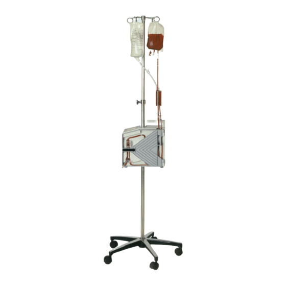
OVERVIEW OF THE BELMONT FMS2000 The complete system consists of the FMS2000 Control System, which is mounted on an IV pole, and the FMS2000 Disposable Set. The FMS2000 can be used only with the supplied disposables. A large volume 3-liter reservoir is available as an optional accessory for convenience in cases involving very large infusion volumes, see page 7. -
Page 8: Control Panel: Display And Keys
CONTROL PANEL: DISPLAY AND KEYS The control panel consists of the touch screen display, which incorporates a bright graphical display with touch pad keys. The display shows status and alarm messages at the top and middle, and contains the touch keys at the bottom. CONTROL PANEL SUMMARY Status Display: ... -
Page 9: Chapter 2: Operation
Do not use with pressure infusers or “bag squeezers”. The system pump provides adequate pressure to infuse fluid. WARNING! ® The Belmont Rapid Infuser, FMS2000, is not for use in warming platelets, cryo-precipitates, or granulocyte suspensions. WARNING! ® The Belmont Rapid Infuser, FMS2000, is intended for infusion of high volume warm replacement fluid or blood component. -
Page 10: Step-By-Step Operating Procedures
1/4" Install the Support Assembly 30" from the ground, if not already installed. Mount the FMS2000 on the IV Pole above the Support Assembly Install the Reservoir Support app. 9" above the top of the system CAUTION: 1. -
Page 11: Installing The Disposable Set
Chapter 2: Operation INSTALLING DISPOSABLE SET 1. Snap reservoir chamber into the WARNING: reservoir support clamp. The disposable set is for single patient use only. Do not reuse. 2. Open the door. Insert heat exchanger with Store the disposable set in a dry well- red arrow pointing up ventilated area free from exposure to (Red tinted tubing to... -
Page 12: Installing The Optional Large Reservoir
Chapter 2: Operation INSTALL OPTIONAL LARGE RESERVOIR, IF NEEDED Install large reservoir holder Install large reservoir Using aseptic techniques, remove the reservoir chamber from the 3-Spike disposable set by disconnecting the luer connectors. Disconnect the larger pump tubing by pressing in the luer lock tab and pulling out the connector. -
Page 13: Powering On The System
Chapter 2: Operation POWER ON Turn power on by firmly pressing the circuit Check that the detachable power cable breaker to the ON position. The system will is securely seated in the main power perform a self-check to check the integrity of receptacle. -
Page 14: Priming The Main System
Chapter 2: Operation PRIME THE MAIN SYSTEM Prime the main system with solution Press PRIME to recirculate 100 ml of fluid at compatible with blood. Do not prime with 500 ml/min to remove air and replace the blood. main system with fluid. The prime volume, 100 ml, countdown is displayed on the screen. -
Page 15: Connecting To Patient
Chapter 2: Operation CONNECT TO THE PATIENT Match infusion set to flow rate and fluid Select an appropriate cannula size for decided type, see chart. flow rate. Using aseptic technique, make patient connection without entrapping air. CAUTION: A single dedicated intravenous access should be used exclusively for infusing blood components and solutions compatible with blood. -
Page 16: Maintain Infusion
Chapter 2: Operation MAINTAIN INFUSION Routinely check patient and system parameters, on screen. Respond to and correct system alarms. CAUTION: Replace reservoir chamber or disposable set when the filter becomes clogged. If it becomes occluded the fluid out sensor will activate, an audible alarm will sound, a message “Fluid Out, Check inlet tubing and Filter. -
Page 17: Recirculation
Chapter 2: Operation RECIRC WARNING: Recirculate fluid, warm, and remove Excessive prolonged recirculation damage red blood cells by exposing them air in the main system at a preset rate of 200 ml/min. Recirculation repeatedly to the rollers inside the pump head. automatically stops and beeps after 5 minutes. -
Page 18: Accidental Power Off
Chapter 2: Operation ACCIDENTAL POWER OFF If the circuit breaker was turned to the STANDBY position while the system is pumping, the system will stop pumping, and alarm. This message is to protect the system from being accidentally powered down during a procedure. -
Page 19: Chapter 3: Alarms And Troubleshooting Guide
ALARMS AND TROUBLESHOOTING GUIDE This chapter describes possible causes for alarm messages with suggestions for corrective actions. When the FMS2000 recognizes a situation that is compromising effective infusing, it stops pumping, heating, moves the valve wand into the recirculate position, displays alarm message, instructions for corrective measure, and sounds an audible alarm. -
Page 20: Door Open
Chapter 3: Alarms and Troubleshooting Guide DOOR OPEN The door is open. Close the door to silence the alarm and resume. No magnet in the Check magnet in the door latch. door latch. If the door is opened while the system pumping, system will... -
Page 21: High Pressure
Chapter 3: Alarms and Troubleshooting Guide ALARM MESSAGE POSSIBLE OPERATOR ACTION CONDITION HIGH PRESSURE Patient line is Make certain that the flow path is not blocked. blocked. Recirculate line is Check that the recirculate line is not blocked. obstructed. Infusion site is not Check that the infusion site is well well placed. -
Page 22: Heating Alarms
Chapter 3: Alarms and Troubleshooting Guide B. HEATING ALARMS: Heating alarms which may occur are: ALARM MESSAGE POSSIBLE CONDITION OPERATOR ACTION HEATING FAULT Wet, dirty or blocked Check disposable set and flow path for disposable set windows. occlusions. Make certain the windows on the “CHECK disposable set and the IR probes are clean TEMPERATURE PROBE... -
Page 23: Hardware Alarms
Chapter 3: Alarms and Troubleshooting Guide C. HARDWARE ALARMS ALARM MESSAGE POSSIBLE CONDITION OPERATOR ACTION AIR DETECTOR Air detector failure Power down and service machine. FAULT “AIR DETECTOR FAULT. TURN OFF POWER, SERVICE MACHINE.” HEATER FAULT Excessive AC power line Press RETRY to try again. -
Page 24: Pump Fault
Chapter 3: Alarms and Troubleshooting Guide ALARM MESSAGE POSSIBLE CONDITION OPERATOR ACTION PUMP FAULT Pump tubing is installed Check that pump tubing is seated on the incorrectly pump head correctly. “PUMP FAULT, CHECK PUMP FOR BLOCKAGE. Pump failure Check that pump turns freely and head is RESTART SYSTEM OR clean. -
Page 25: Troubleshooting Other Operational Difficulties
Chapter 3: Alarms and Troubleshooting Guide TROUBLESHOOTING OTHER OPERATIONAL DIFFICULTIES Problems may occur that are outside the surveillance system due to improper setup, faulty accessory equipment, or internal failure of a component. Table below describes several of these potential problems, the alarm that might be generated (if any), and the corrective actions to take. PROBLEM POSSIBLE CONDITION OPERATOR ACTION... - Page 26 Chapter 3: Alarms and Troubleshooting Guide PROBLEM POSSIBLE CONDITION OPERATOR ACTION IGBT’s on Driver ‘A’ and ‘B’ Power off If the problem persists, power down and immediately after shorted. service machine. switch to ON. System turns on for EPROM is not seated in 2-3 seconds, then the socket properly.
-
Page 27: Chapter 4: Parameters Setting And Preventive Maintenance
PARAMETERS SETTING AND PREVENTIVE MAINTENANCE ® The Belmont Rapid Infuser, FMS2000, requires minimal service and care. Preventive maintenance should be performed regularly to optimize performance and reduce the likelihood of downtime. Listed below are routine maintenance (as needed), periodic maintenance (at least once a year), and parameters setting. -
Page 28: System Setup
Parameter Setup changes is performed in the Service mode. Pressing the SERVICE key accesses the Calibration/Set-up mode. This key appears on the BELMONT logo screen only at system powered-up. This screen remains active for 4.5 seconds before the system enters the Prime mode. -
Page 29: Date/Time
Chapter 4: Parameters Setting and Preventative Maintenance Date/Time Press DATE TIME in the CALIBRATION/SET-UP screen to set the time and date. Press either the TIME or DATE key. Screen after pressing DATE TIME key A numerical keypad will be displayed. Enter the appropriate time or date information. Enter the appropriate time in 24-hour clock format (i.e. -
Page 30: Display Brightness
Chapter 4: Parameters Setting and Preventative Maintenance Display Brightness There are nine levels of display brightness. Press DISPLAY BRIGHT to change the present level of brightness to the next level. Key Rate The key rate sets up the sensitivity of the touch keys. There are three different levels of sensitivity;... -
Page 31: Service And Preventive Maintenance Schedule
Chapter 4: Parameters Setting and Preventative Maintenance SERVICE AND PREVENTIVE MAINTENANCE SCHEDULE Schedule 1 To be performed by either the Clinical User or a Biomedical Technician (BMET). Interval Routine Maintenance Before or After Every Every 6 Each Use Month Months ... -
Page 32: Routine Maintenance
Chapter 4: Parameters Setting and Preventative Maintenance ROUTINE MAINTENANCE Clean and/or Disinfect Exterior Clean the outside surfaces of the system and inside the door after each use. Turn the pump to STANDBY and unplug the power cord. Wipe the surface with a cloth moistened with water or isopropyl alcohol. Note: Avoid the use of acetone or other solvents that might damage the surface. -
Page 33: Instrument Door And Ceramic Disks
Chapter 4: Parameters Setting and Preventative Maintenance Instrument Door and Ceramic Disks The instrument door must fit properly for the system to operate correctly. The platen part of the roller pump is located on the door. The platen must line up properly with the pump. Check hinges for blood build-up, clean any dried blood from hinge area. -
Page 34: Testing The System And Operational Check-Out
The device should be serviced periodically, in accordance to schedule 1 and 2, by a qualified technician. Material Required: FMS2000 Disposable Set, REF 903-00006 Bio-Tek Safety Analyzer or equivalent Saline or other crystalloid for testing 2 liters of 35º - 42ºC fluid... -
Page 35: System Operational Checkout
Chapter 4: Parameters Setting and Preventative Maintenance System Operational Check-Out Install Disposable set. Turn power switch ON. Wait for PRIME screen to appear. Close bag clamps. Hang and spike fluid bag. Open bag clamp(s). Press PRIME to prime the system (circulate 100 ml of fluid at 500 ml/min.) Prime volume (100 ml) countdown is displayed on screen. -
Page 36: Electrical Safety Test - Leakage Current
Install the disposable set and prime with saline and proceed to the Infuse screen. Press STOP to set the pump at 0 ml/min, not heating or pumping. Repeat iii & iv with the FMS2000 in ON mode (power switch ON, infuse screen displayed, not pumping or heating). vii. - Page 37 Safety Analyzer large clamp to the cannula or needle tip. iii. Prime the FMS2000 with saline. Make sure that the entire patient line including the cannula has been primed. Repeat a.iii, and a.iv with the FMS2000 in the STANDBY, ON, and pumping at 750 ml/min modes.
-
Page 38: Hardware Verification
Chapter 4: Parameters Setting and Preventative Maintenance Hardware Verification Install and prime the disposable set before beginning the Hardware Verification process. Hardware mode verifies: Valve operation Fluid Out and Air Detectors Battery voltage. Flow Rate (Pump speed) Input and Output Temperature Probes including “Over Temperature” alarm test, and Pressure sensor. - Page 39 Chapter 4: Parameters Setting and Preventative Maintenance Hardware Status Screen Status Line Reading Pump Speed 0, 10, 100, 500, 750, and an optional 1000 ml/min Input Temperature Temperature in ºC, probe ambient reference in parentheses Output Temperature Temperature in ºC, probe ambient reference in parentheses Pressure Pressure in mmHg Fluid Out Detector Status Air or Fluid...
- Page 40 Chapter 4: Parameters Setting and Preventative Maintenance Hardware Verification: Valve Press LEFT VALVE, confirm that the valve wand (valve pincher) moves to the left. Press OPEN VALVE, confirm that valve wand moves to the middle position. iii. Press RIGHT VALVE, confirm that the valve wand moves to the right. Leave the valve in the LEFT VALVE position before continuing to the next step.
- Page 41 Chapter 4: Parameters Setting and Preventative Maintenance Measure by using a tachometer: Close the door. Set the pump speed to 10 ml/min. Use a tachometer to measure the rotational speed of the pump head. The accepted tolerance is 1.95 rpm ± 25%. Press PUMP SPEED again to change the pump speed to 100 ml/min.
- Page 42 Chapter 4: Parameters Setting and Preventative Maintenance Pressure Transducer WARNING! Do not apply excessive pressure to the pressure chamber or pressure transducer. The pressure transducer is a precision electromechanical device and can be damaged with excessive force. Do not use the system if the pressure transducer is damaged.
-
Page 43: Clean The Pump Head
Chapter 4: Parameters Setting and Preventative Maintenance Clean Pump Head Roller Pump Retaining Screw The pump head can be removed and cleaned if needed. Turn the pump to STANDBY and unplug the power cord. Unscrew the retaining screw that holds the pump head. Remove the pump head and clean with water and soap. -
Page 44: Checklist
Chapter 4: Parameters Setting and Preventative Maintenance CHECKLIST FMS2000 S/N: Tested By: Date: Equipment Safety Analyzer S/N: Cal Due Date: Used: Pressure Source S/N: Cal Due Date: Thermometer S/N: Cal Due Date: Tachometer S/N: Cal Due Date: Results 1. Visual Inspection a. - Page 45 Chapter 4: Parameters Setting and Preventative Maintenance Electrical Safety Test - Leakage Current Results Sheet Earth Leakage Currents (all measurements are in μA) Polarity - N; Polarity - R; Polarity - R; Polarity - N; Ground - N Ground - N Ground - O Ground - O Unit in STANDBY...
-
Page 46: Electromagnetic Compatibility
Chapter 4: Parameters Setting and Preventative Maintenance ELECTROMAGNETIC COMPATIBILITY WARNING! Medical Electrical Equipment needs special precautions regarding EMC and needs to be installed and put into service according to the Electromagnetic Compatibility [EMC] information provided in the accompanying documents. WARNING! Portable and Mobile RF Communications Equipment can affect Medical Electrical Equipment. - Page 47 Table 201 Guidance and Manufacturer’s Declaration – Emissions All Equipment and Systems ® is intended for use in the electromagnetic environment specified below. The Belmont Rapid Infuser, FMS2000 ® customer or user of the Belmont Rapid Infuser, FMS2000 should assure that it is used in such an environment.
-
Page 48: Fuse
Chapter 4: Parameters Setting and Preventative Maintenance FUSE The fuse on the AC/DC supply marked F1 is rated as 1.25A, 250V, fast acting, 5x20mm. CALL FOR SERVICE 1-855-397-4547 US/Canada 1-978-663-0212 Worldwide Prior to returning any product, please obtain a Return Goods Authorization (RGA) number. Before calling, please have the serial number of the unit. -
Page 49: Chapter 5: Technical Specifications
Chapter 5: Technical Specifications Technical Specifications of the Belmont FMS2000 DIMENSION Size 13.5" x 12" x 7.5" (34.29cm x 30.48cm x 19.05cm) Weight 28 lbs (12.7 Kg) PORTABILITY Hand Carry Handle on top of unit for easy transport IV Pole Mount IV pole mountable or free standing. -
Page 50: Environment
Chapter 5: Technical Specifications ENVIRONMENTAL Operating Temperature 10ºC to 32ºC (50ºF to 90ºF) Storage Temperature -15ºC to 40ºC Relative Humidity 10% to 90% Pressure 49-103 kPa Shock and Vibration Meet MIL STD.810E method 514.4 (Basic Transportation) OPERATING PARAMETERS Flow Rate 10 -750 ml/min, with a 1000 ml/min as an option, in 10 ml/min steps plus 2.5 and 5.0ml/min with fluids of viscosity 1 to 8 centipoise (Water and crystalloid fluids... -
Page 51: Operating Panel
Chapter 5: Technical Specifications OPERATING PANEL Control Panel and Display Splash proof touch screen display Display Area 5" X 2.5" (12.7cm X 6.35cm) Status Display Flow rate (ml/min) Total volume infused (ml) Line pressure (mm hg) Output infusate temperature ( ºC ) Bolus volume (ml) Alarm messages Functional Keys... -
Page 52: Alarm States And Controls
Chapter 5: Technical Specifications ALARM STATES AND ALARM MESSAGES CONTROLS Operator Setting, User- MISSING DISPOSABLE correctable DOOR OPEN FLUID OUT AIR DETECTION HIGH PRESSURE System Status LOW BATTERY System Failures AIR DETECTOR FAULT PUMP FAULT VALVE FAULT HEATER FAULT LATCH HEAT POWER READ BACK FAULT HEATER OVER POWER FAULT POWER MODULE OVERTEMP... -
Page 53: Classifications
Chapter 5: Technical Specifications Classifications Type of Protection Against Class I, or internally powered Electric Shock Degree of Protection Against CF defibrillator-proof Electric Shock Degree of Protection Against IPX2 Harmful Ingress of Water Method of Sterilization Ethylene Oxide. Disposable delivered sterile, with pyrogen-free flow path, for single use only Degree of Safety in Presence Not suitable... -
Page 54: Symbols And Definition
Chapter 5: Technical Specifications Symbols and Definitions Symbol Description Compliance to Medical Device Directive 93/42/EEC Alternating current Equipotentiality Standby Caution Consult accompanying documents/refer to manual Defibrillator-proof type CF equipment IPX2 Protected against dripping water Serial Number Manufactured by Authorized European Representative...
Need help?
Do you have a question about the FMS2000 and is the answer not in the manual?
Questions and answers