Table of Contents
Advertisement
Quick Links
THANK YOU
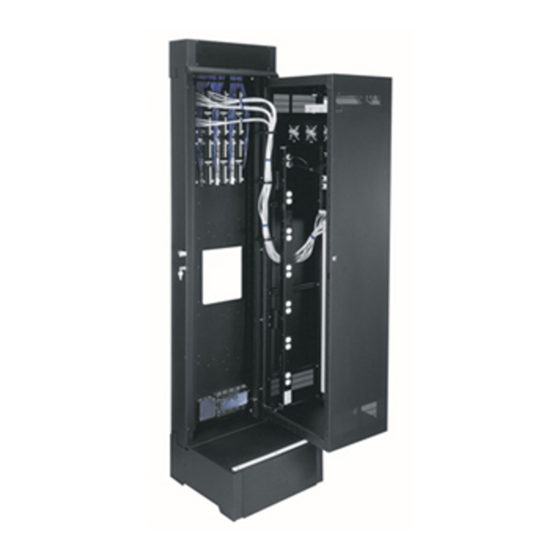
Thank you for purchasing the SR Series Pivoting Rack. Please read these instructions thoroughly
before installing or assembling this product.
PRODUCT FEATURES
• Lever Lock™ compatible in center section and back pan for small device mounting and cable
management.
• Forward Compatible for 5x faster tool free system integration.
• Available in 23.5" and 29" widths.
• 29" Widths include front vertical cable management for clean and organized look.
• Tool-Free Quick-Mount system for easy mounting of the center section to the
backpan.
• Pivots 90 off the wall for access to rear connections.
• Zero Clearance Latch (Optional) allows side-by-side mounting or interior
corner mounting.
Instruction Sheet
SR SERIES
PIVOTING RACK
100-00031
Rev A
Advertisement
Table of Contents

Subscribe to Our Youtube Channel
Related Manuals for Middle Atlantic Products SR Series


Summary of Contents for Middle Atlantic Products SR Series
- Page 1 SR SERIES PIVOTING RACK THANK YOU Thank you for purchasing the SR Series Pivoting Rack. Please read these instructions thoroughly before installing or assembling this product. PRODUCT FEATURES • Lever Lock™ compatible in center section and back pan for small device mounting and cable management.
-
Page 2: Important Safety Instructions
Braced according to specifications set forth by licensed architects and engineers, the Middle Atlantic Products rack/enclosure you purchased is capable of sustaining a phenomenal lateral load. Refer to the seismic data published on seismic letter on the Middle Atlantic Product website. -
Page 3: Weight Ratings
Contreventé conformément aux spécifica- tions établies par des architectes et ingénieurs agréés, le rack/boîtier Middle Atlantic Products que vous avez acheté est capable de supporter une charge latérale phénoménale. Reportez-vous aux données sismiques publiées sur la lettre sismique sur le site Web du produit Middle Atlantic. -
Page 4: Required Tools
SPEICIFICATIONS Width: 23.5” (597mm) and 29” (736.6mm) Height: 24, 40, and 46 RU Depth: 22” (558.8mm), 28” (711.2mm), and 32” (812.8mm) NOTE: Not all depths available in all heights. SUPPLIED COMPONENTS AND HARDWARE If any pieces are missing or damaged, please report it immediately to Technical Support at av.support@legrand.com or (866) 977-3901. - Page 5 REVERSING THE PIVOT DIRECTION This rack is factory configured for a right-hand pivot and may be Upper Wire reversed using the following procedure: Chamber 1. If upper wire chamber is already installed, use power driver and 5/16” socket to remove (4x) screws and take it off the backpan (A).
- Page 6 This easy to install option upgrades new SR Series enclosures to allow the center section (B) to lock closed without the need for side latches. Open by pulling the convenient FIGURE C front-mounted handle as shown.
- Page 7 PRIOR TO MOUNTING BACKPAN TO WALL NOTE: • When installing next to another SR or wall using the zero clearance latch option, perform the support base (C) installation for access to the base screws before mounting the backpan (A). For more information, see “Installing the Base”...
- Page 8 MOUNTING THE BACKPAN TO CONCRETE BLOCK (INSTALL NOT EVALUATED BY UL) CAUTION: The backpan must be installed plumb and level for proper operation. ATTENTION: La plaque profilée doit etre aplomb et de niveau pour un fonctionnement. 1. Align backpan (A) to selected wall location and mark pilot holes through wall mounting points as shown.
-
Page 9: Installing The Base
INSTALLING THE BASE 1. Use power driver and 3/8” socket to remove (2x) 3/8” screws pre-installed on the bottom foot of the backpan (A). (FIGURE L) NOTE: If using power driver, verify the torque is on the lightest setting and only increase as necessary. 2. - Page 10 MOUNTING THE CENTER SECTION TO THE BACKPAN NOTE: The pivot pins and security clips needed to mount the center section (B) to the backpan (A) are pre-installed in the bushings on the backpan top and bottom. (FIGURE P) 1. Remove the clips and unscrew the pins. Security Clip NOTE: Use slip joint pliers to carefully remove the pins, if necessary.
- Page 11 MOUNTING THE CENTER SECTION TO THE BACKPAN (CONTINUED) 6. Keeping the center section (B) in the closed position, insert a pivot pin through the bottom access hole into Upper bushing, hand tighten fully, and then back out one Wire Chamber turn.
- Page 12 INSTALLING POWER STRIPS Compatible Middle Atlantic Products power strips can be mounted inside the trim (E) with the included hardware. This simplifies cable management by requiring no additional accessories. NOTE: Reference which power strip models are compatible with your specific size enclosure at www.middleatlantic.com.
-
Page 13: Grounding And Bonding
GROUNDING AND BONDING Protective Earth Terminals (PET) are located in backpan of the wall rack. These terminals are marked with the symbol Wall rack parts, center section and door, contain or are provided with bonding points for connection to the backpan / PET. Protective earth and bonding connections shall be in accordance with Article 250 of the National Electric Code. -
Page 14: Warranty
WARRANTY For warranty information, refer to legrandav.com/policies/warranty_information. Corporate Headquarters P: (866) 977-3901 | F: (877) 894-6918 | legrandav.com | av.support@legrand.com Middle Atlantic Canada P: (888) 766-9770 | F: (888) 599-5009 | ca.middleatlantic.com | av.canada.customerservice@legrand.com Middle Atlantic EMEA Technical Support P: +31 495-726-003 | av.emea.middleatlantic.support@legrand.com Factory Distribution United States: New Jersey, California, and Illinois | Canada: Ontario | The Netherlands: Weert At Legrand AV Inc.
Need help?
Do you have a question about the SR Series and is the answer not in the manual?
Questions and answers