Table of Contents
Advertisement
Quick Links
Advertisement
Chapters
Table of Contents

Subscribe to Our Youtube Channel
Related Manuals for Jetter JXM-IO-EX30


Summary of Contents for Jetter JXM-IO-EX30
- Page 1 User Manual JXM-IO-EX30 Expansion module 60886108_00 We automate your success.
- Page 2 Revisions and further development of our products are not automatically mentioned in a reviewed document. Jetter AG shall not be liable for errors in form or content, or for missing updates, as well as for damages or disadvantages resulting from such failure.
-
Page 3: Table Of Contents
2 Safety .............................. 6 General information........................ 6 Purpose ............................ 6 2.2.1 Usage other than intended .................... 6 Warnings used in this document .................... 6 Safety-related shutdown of the JXM-IO-EX30 ................ 7 3 Product description .......................... 9 Design ............................ 9 Features ............................. 10 Diagnostic capability via LEDs .................... 10 Nameplate .......................... 13 Scope of delivery........................ 13... - Page 4 7.12.2 Current measurement at the PWMi_H3_X outputs ............ 56 7.13 Dither technology for controlling hydraulic valves .............. 57 8 Maintenance and repairs ........................ 58 Maintenance, repairs and disposal..................... 58 Storage and shipment ........................ 58 9 Spare parts and accessories ...................... 59 Accessories .......................... 59 JXM-IO-EX30 User Manual...
-
Page 5: Introduction
For information on new revisions of this document, visit the download area on our website. This document is not subject to any updating service. Start | Jetter - We automate your success. For further information refer to the following information products: ■... -
Page 6: Safety
Low risk CAUTION Indicates a hazardous situation which, if not avoided, could result in minor or moderate injury. Material damage NOTICE Indicates a situation which, if not avoided, could result in malfunctions or material damage. JXM-IO-EX30 User Manual 6 / 63... -
Page 7: Safety-Related Shutdown Of The Jxm-Io-Ex30
Safety | 2 2.4 Safety-related shutdown of the JXM-IO-EX30 The JXM-IO-EX30 itself has not been designed to be functionally safe. With an external disconnection of the actuator supply voltage (VBAT_PWR) via safety relay, it is possible to achieve Performance Level b in accordance with ISO 13849. -
Page 8: Fig. 1 Wiring Example Of Safety Relay
Jetter AG Safety | 2 Wiring - example Reset/Start Fig. 1: Wiring example of safety relay Signal X2:1 VBAT_PWR X2:2 VBAT_PWR X2:3 GND_PWR X2:4 GND_PWR Tab. 1: Connector X2 - VBAT_IN JXM-IO-EX30 User Manual 8 / 63... -
Page 9: Product Description
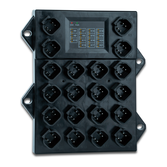
Jetter AG Product description | 3 3 Product description The JXM-IO-EX30 expansion module is a universal building block for mobile ma- chinery. With its I/O configuration, it can handle almost all distributed tasks. 3.1 Design Fig. 2: Design Fastening lugs Error and status LEDs... -
Page 10: Features
3.3 Diagnostic capability via LEDs The node has 2 status LEDs (red and green) to indicate various states and errors as well as 30 amber LEDs to indicate the status of the individual connectors: Fig. 3: LED indicators JXM-IO-EX30 User Manual 10 / 63... - Page 11 The following errors may have oc- curred: Stead ■ The PCB temperature is too high. 400 ms ■ The CPU temperature is too high. Green 400 ms ■ The maximum total current consumption 200 ms is exceeded. JXM-IO-EX30 User Manual 11 / 63...
- Page 12 OPEN_CIRCUIT CC_UNLOCK Detecting LED In the power-up phase (bootup), all amber LEDs light up for 2 seconds and are faults then off for one second. This lets you detect functional errors of individual LEDs. JXM-IO-EX30 User Manual 12 / 63...
-
Page 13: Nameplate
Fig. 4: Nameplate 1 Company logo Registration number Certification mark Model code number Fig. 5: Nameplate 2 Item number Data matrix code Serial number Hardware revision 3.5 Scope of delivery Scope of delivery Item number Quantity JXM-IO-EX30 10001969 JXM-IO-EX30 User Manual 13 / 63... -
Page 14: Technical Specifications
Jetter AG Technical specifications | 4 4 Technical specifications This chapter contains information on electrical and mechanical data, as well as on operating data of the JXM-IO-EX30. 4.1 Dimensions 130,5 Fig. 6: Dimensions in mm JXM-IO-EX30 User Manual 14 / 63... -
Page 15: Mechanical Specifications
49 mA + total cur- rent at VEXT_SEN At 24 V approx. 34 mA + total cur- rent at VEXT_SEN Tab. 4: ECU power supply Ground reference Purpose GND_PWR Ground for VBAT_PWR and VBAT_ECU GND_SEN Ground for VEXT_SEN Tab. 5: Ground reference JXM-IO-EX30 User Manual 15 / 63... -
Page 16: Environmental Conditions
Salt water resistance The device is not designed for maritime applications. Degree of protection IP65 without mating connector IP69K with Jetter mating connector Maximum installation alti- 2000 m tude above sea level Degree of pollution Tab. 6: Environmental conditions... -
Page 17: Outputs
Switching the interface to NPN or PNP affects the entire PWMi_H3_x group! L level ≤ 1.6 V H level ≥ 4.6 V Input resistance PNP 94 kΩ NPN 10 kΩ Tab. 13: Outputs PWMi_H3_1 ... PWMi_H3_4 JXM-IO-EX30 User Manual 17 / 63... -
Page 18: Tab. 14 Outputs Pwm_H7_1
Switching the interface to NPN or PNP affects the entire DO_H3_x group! L level ≤ 1.6 V H level ≥ 4.6 V Input resistance PNP 94 kΩ NPN 10 kΩ Tab. 15: Outputs DO_H3_1 ... DO_H3_4 JXM-IO-EX30 User Manual 18 / 63... -
Page 19: Current Diagnostics At The Outputs
The measurement is therefore linearized by the firmware: Fig. 7: Graph: Principle of linearization Current value ADC value T1 is 200 mA. Current below this value is displayed as 0. T2 is 500 mA. From 500 mA to 200 mA the measured current value is linearized. JXM-IO-EX30 User Manual 19 / 63... -
Page 20: Overcurrent Shutdown At Outputs
At the end of the overcurrent event, the current measurement is automatically resumed. As DI_PNP H level ≥ 4.6 V L level ≤ 1.6 V Input frequency Max. 10 Hz Input resistance ≥ 35 kΩ Tab. 17: Analog inputs JXM-IO-EX30 User Manual 20 / 63... -
Page 21: Tab. 18 Digital Inputs Di_P_1
VBAT_ECU or GND via an offset. Category Description Configuration inputs for configuring the node ID Abbreviation CFG_1 CFG_2 Quantity Tab. 19: Configuration inputs CFG_1 … CFG_2 For more information refer to chapter Setting the node ID JXM-IO-EX30 User Manual 21 / 63... -
Page 22: Mechanical Installation
■ Sufficient air circulation Requirements for ■ Sufficient space between the device and parts that may become very hot the installation ■ The device must be accessible for service work at all times. space JXM-IO-EX30 User Manual 22 / 63... -
Page 23: Mounting Orientation
Mechanical installation | 5 5.2 Mounting orientation The JXM-IO-EX30 has 4 fastening lugs which let you screw it to the mounting surface. We recommended to use screws with a diameter of at least 6 mm. The torque of the screws must not exceed 4 Nm. -
Page 24: Electrical Connection
Surges resulting from missing protection or fusing NOTICE Surges may cause malfunctions or damage to the product. ► Protect the voltage inputs from surges according to the requirements. ► Ensure that the device is handled in accordance with ESD regulations. JXM-IO-EX30 User Manual 24 / 63... -
Page 25: Connector Specification
Jetter AG Electrical connection | 6 6.1 Connector specification 6.1.1 4-pin Deutsch connectors The JXM-IO-EX30 features 20 4-pin Deutsch connectors. Fig. 9: Connectors Connector X1 - Signal VBAT_OUT n. c. VBAT_PWR GND_PWR GND_PWR Tab. 21: Connector X1 - VBAT_OUT Connector X2 -... -
Page 26: Tab. 23 Connector X4 - Can_In
Connector X9 - Signal AI_7 ... AI_8 VEXT_SEN_2 AI_7 GND_SEN AI_8 Tab. 28: Connector X9 - AI_7 ... AI_8 Connector X10 - Signal DI_P_1 ... DI_P_2 VEXT_SEN_3 DI_P_1 GND_SEN DI_P_2 Tab. 29: Connector X10 - DI_P_1 ... DI_P_2 JXM-IO-EX30 User Manual 26 / 63... -
Page 27: Tab. 30 Connector X11 - Di_P_3
Tab. 34: Connector X15 - DO_H3_1 ... DO_H3_2 Connector X16 - Signal PWM_H7_3 VEXT_SEN_3 PWM_H7_3 GND_PWR PWM_H7_3 Tab. 35: Connector X16 - PWM_H7_3 Connector X17 - Signal PWM_H7_6 VBAT_ECU PWM_H7_6 GND_PWR PWM_H7_6 Tab. 36: Connector X17 - PWM_H7_6 JXM-IO-EX30 User Manual 27 / 63... -
Page 28: Tab. 37 Connector X18 - Pwmi_H3_3
Ground - sensor power supply Configuration pin for setting the CAN ID. n. c. Reserved pin that must not be connected! Seal un- used pins with pin plugs. Tab. 41: Abbreviations used in this document JXM-IO-EX30 User Manual 28 / 63... -
Page 29: Programming
Alternatively, you can update the device from a controller by Jetter. Required OS version OS files with a version < 2.16.0.00 can not be imported into the JXM-IO-EX30. When you try to import an OS file with a version < 2.16.0.00, the following happens: ■... -
Page 30: Setting The Node Id
2 - 3 and 1 - 4 1 - 2 and 1 - 4 Tab. 43: CFG pin jumpers INFO Seal unused plugs with a dummy plug [} 59]. It is also used to set the node ID 00. JXM-IO-EX30 User Manual 30 / 63... -
Page 31: Concept And Control
7.3 Concept and control The concept of the JXM-IO-EX30 is based on the assignment of interfaces to the inputs and out- puts of the device. Each input and output of the device is called a port and can be configured. -
Page 32: Io Ports And Sdo Map
Opera- tional to Pre-Operational state. Only possible in the Operational state, otherwise an error occurs (SDO abort). 50 … 199 Parameter Tab. 46: Subindeces for accessing parameters, values, and statuses JXM-IO-EX30 User Manual 32 / 63... -
Page 33: Available Interfaces, Parameters, Values And Statuses
(0...24 mA) INACTIVE DI_PNP SENSOR_SUPPLY I_DIGITAL SUPPLY_FAULT Digital ERROR input INACTIVE (active-high with pull-down) FI_PNP SENSOR_SUPPLY I_DIGITAL TIMEOUT Frequency TIMEOUT_TIME I_COUNTER SUPPLY_FAULT input GATE_TIME I_FRQ ERROR (active-high with I_DUTY_CYCLE INACTIVE pull-down) I_PERI- ODIC_TIME I_H_PULSE_TIME I_L_PULSE_TIME JXM-IO-EX30 User Manual 33 / 63... - Page 34 OVERCURRENT_TIME OPEN_CIRCUIT FILTER_DEEP MIN_DEVIATION MIN_CURRENT OPENCIRCUIT_DETEC- TION SENSOR_SUPPLY DO_HS3 MAX_CURRENT O_DIGITAL OVERCURRENT High-side FILTER_DEEP I_HCURRENT SUPPLY_FAULT digital output OVERCURRENT_TIME ERROR (up to 3 A) MIN_DEVIATION INACTIVE MIN_CURRENT OPEN_CIRCUIT OPENCIRCUIT_DETEC- TION SENSOR_SUPPLY Reserved Reserved JXM-IO-EX30 User Manual 34 / 63...
- Page 35 MAX_CURRENT INACTIVE OVERCURRENT_TIME OPEN_CIRCUIT FILTER_DEEP MIN_DEVIATION MIN_CURRENT OPENCIRCUIT_DETEC- TION SENSOR_SUPPLY 12/c DO_HS7 MAX_CURRENT O_DIGITAL OVERCURRENT High-side FILTER_DEEP I_HCURRENT SUPPLY_FAULT digital output OVERCURRENT_TIME ERROR (up to 7 A) MIN_DEVIATION INACTIVE MIN_CURRENT OPEN_CIRCUIT OPENCIRCUIT_DETEC- TION SENSOR_SUPPLY JXM-IO-EX30 User Manual 35 / 63...
-
Page 36: Io Interfaces
1 µs I_HPULS_TIME H pulse time 1 µs I_LPULS_TIME L pulse time 1 µs I_DIRECTION Current direction 0 … 2 0 = no movement 1 = forward 2 = backward Tab. 48: IO interface input values JXM-IO-EX30 User Manual 36 / 63... -
Page 37: Tab. 49 Io Interface Output Values
I_DIREC- TION signals no movement. CURRENT_ Cycle time of current control U32 1 ms CONTROL_TIME FILTER_DEEP Moving average calculation 1 … 32 depth GATE_TIME Measuring time of the fre- 1 ms quency measurement JXM-IO-EX30 User Manual 37 / 63... -
Page 38: Tab. 51 Status Of Io Interface
An undefined error has occurred. 0x00000004 CONFIG A configuration error has occurred. 0x00000008 OVERVOLTAGE Overvoltage is present at the input. 0x00000010 OVERCURRENT Overcurrent is present at the input/output. 0x00000020 SUPPLY_FAULT The supply voltage VEXT_SEN is not correct. JXM-IO-EX30 User Manual 38 / 63... -
Page 39: Device Information
Unit cess 0x2000 Number of supported entries VBAT_PWR 7V IO PCB temperature 0.1 °C CPU temperature 0.1 °C CPU VRef SPWR1 SPWR2 SPWR3 VBAT_ECU CFG_1_IN CFG_2_OUT Total current ±50 % Tab. 53: Diagnostic information JXM-IO-EX30 User Manual 39 / 63... -
Page 40: Tab. 54 Eds Information
Index Subindex Description Type Type of access 0x1001 Error register Bit 0 Generic error Bit 1 Total overcurrent Bit 3 Temperature Bit 4 Communication error Bit 7 CI error (invalid input) Tab. 56: Status information JXM-IO-EX30 User Manual 40 / 63... -
Page 41: Saving Settings Permanently And Resetting To Default Values
The vehicle controller reads the CRC via index 0x4556, subindex 1 and saves this value lo- cally remanently. After a restart of the JXM-IO-EX30 the vehicle controller compares the locally stored CRC value with the value in index 0x4556, subindex 1. If the values do not match, parameteriza- tion must be restarted. -
Page 42: System Parameters
The transmit PDOs (TPDO 1 ... 4) and receive PDOs (RPDO 1 ... 4) are set using the following parameters. INFO ® More information on the subject CANopen is available in our application- oriented manuals on our homepage. JXM-IO-EX30 User Manual 42 / 63... -
Page 43: Tab. 60 Rpdo Communication Parameters
PDOs) Index 0x1801 0x280 + node Index 0x1802 0x380 + node Index 0x1803 0x480 + node Transmission Acyclic type = 0 Type Inhibit Time 0.1 ms Event Time 1 ms Tab. 61: TPDO communication parameters JXM-IO-EX30 User Manual 43 / 63... -
Page 44: Mapping Tables
First object that is mapped 6000 01 08h Second object that is mapped 6000 02 08h Third object that is mapped 6000 03 08h Fourth object that is mapped 6000 04 08h … 64. Object to be mapped JXM-IO-EX30 User Manual 44 / 63... -
Page 45: Tab. 64 Mapping Entry U32
Fourth object that is mapped 6401 0C 10h … 64. Object to be mapped Tab. 63: TPDO mapping table Mapping entry U32 Byte 2 and 3 Content Bit length Subindex Index Tab. 64: Mapping entry U32 JXM-IO-EX30 User Manual 45 / 63... -
Page 46: Mapping Of Digital Values
Bit 4 … bit 7: PWMi_H7_1 … PWMi_H7_4 Bit 0 … bit 1: PWMi_H7_5 … PWMi_H7_6 Bit 2 … bit 5: DO_H3_1 ... DO_H3_4 Bit 6 ... bit 7: not used Tab. 66: CAN object 0x6200 - Digital outputs JXM-IO-EX30 User Manual 46 / 63... -
Page 47: Mapping Of Analog Values
17 … 22 PWM_H7_1 … PWM_H7_6 U16, 23 … 26 DO_H3_1 … DO_H3_4 U16, Tab. 67: CAN objects 0x6401 and 0x6402 - Analog inputs ■ Object 0x6401 = 16-bit accesses ■ Object 0x6402 = 32-bit accesses JXM-IO-EX30 User Manual 47 / 63... -
Page 48: Tab. 68 Can Objects 0X6411 And 0X6412 - Analog Outputs
Subindex Description Type access value 0x6411 Number of supported entries 1 … 4 PWMi_H3_1 … PWMi_H3_4 U16, 0x6412 5 … 10 PWM_H7_1 … PWM_H7_6 U16, Tab. 68: CAN objects 0x6411 and 0x6412 - Analog outputs JXM-IO-EX30 User Manual 48 / 63... -
Page 49: Stx Example: Output Value Ai1 Voltage To Tpdo1
SDOACCESS_FINISHED(iBusy) continue; //Validating object, setting uppermost bit to 0, specifying PDO COB dTemp := 0x180+0x30; CanOpenDownloadSDO( cCanChannel, cJXMNodeId, 0x1800, 1, CANOPEN_DWORD, 4, dTemp, iBusy); when SDOACCESS_FINISHED(iBusy) continue; //Switching JXM-IO-EX30 to OPERATIONAL CanOpenSetCommand( cCanChannel,CAN_CMD_NMT,CAN_CMD_NMT_Value( cJXMNodeId,CAN_NMT_OPERATIONAL)); JXM-IO-EX30 User Manual 49 / 63... -
Page 50: Frequency Measurement At The Digital Inputs
To do this, it is necessary to calculate the values I_HPULSE_TIME and I_LPULSE_TIME externally: f [mHz] = 10 / (I_HPULSE_TIME + I_LPULSE_TIME) INFO Decrease of resolution In pulse length measurement, the resolution decreases with increasing frequency. JXM-IO-EX30 User Manual 50 / 63... -
Page 51: Acquisition Of Encoder Signals
The timeout_TIME parameter lets you determine the lowest speed that can still be detected. The default value is 100 ms, i.e. if no more pulses are received for 100 ms, then I_DIRECTION = 0. JXM-IO-EX30 User Manual 51 / 63... -
Page 52: Troubleshooting
Recovered from bus-off 0x8210 Processing errors due to incorrect length of PDOs 0x8220 PDO length exceeded 0xff00 Configuration error on the device 0xff01 IO port OVERVOLTAGE 0xff02 IO port OVERCURRENT 0xff03 IO port SUPPLYFAULT JXM-IO-EX30 User Manual 52 / 63... -
Page 53: Current Control With Pid Controller
Tab. 74: Emergency Error Codes 7.12 Current control with PID controller The individual P, I and D controllers usually have the following characteristics: Fig. 11: Comparison of controller types in a control loop Step response Time JXM-IO-EX30 User Manual 53 / 63... -
Page 54: Test Scenario
Jetter AG Programming | 7 7.12.1 Test scenario The PID controller was tested on JXM-IO-EX30 the under the following conditions: Condition Description Output 1 kHz PWM Control period 10 ms Load Inductive An unspecified valve solenoid VBAT 24 V In case of a short circuit 4.8 A ~5 Ω... -
Page 55: Fig. 13: Test Scenario With The Control Parameters P=100,000, I=5,000, D=0
The I controller also works satisfactorily, the setpoint is reached with this setting. Closed-loop control parameters: P=100,000, I=5,000, D=400, Measurements: blue=setpoint, red=actual value Fig. 14: Test scenario with the control parameters P=100,000, I=5,000, D=400 The D controller causes the actual value to approach the setpoint more quickly. JXM-IO-EX30 User Manual 55 / 63... -
Page 56: Current Measurement At The Pwmi_H3_X Outputs
Purely resistive loads can be operated on the controller if the PWM frequency is set to 1 KHz. The low-pass filter mentioned above is provided for this purpose. For lower frequencies (e.g. 100 Hz) the current measurement at purely resistive loads is too inaccurate. JXM-IO-EX30 User Manual 56 / 63... -
Page 57: Dither Technology For Controlling Hydraulic Valves
■ Decrease the amplitude of the dither signal. ■ Use the averaging filter on the current feedback of the output. ■ Adjust the PID parameters. JXM-IO-EX30 User Manual 57 / 63... -
Page 58: Maintenance And Repairs
In case of damaged packaging inspect the device for any visible damage, and in- form your freight forwarder and the Jetter AG of the damage caused during ship- ment. If the device is damaged or has been dropped, it is strictly forbidden to use... -
Page 59: Spare Parts And Accessories
NOTICE Parts and equipment from other manufacturers might impede the function of the device and cause damage to the product. ► Only use accessories recommended by Jetter AG. 9.1 Accessories INFO Ordering accessories The accessories are not part of the scope of delivery. - Page 60 Fig. 13 Test scenario with the control parameters P=100,000, I=5,000, D=0 ........Fig. 14 Test scenario with the control parameters P=100,000, I=5,000, D=400 ........ Fig. 15 Test scenario with the control parameters P=100,000, I=10,000, D=400 ....... Fig. 16 Dither technology ........................JXM-IO-EX30 User Manual 60 / 63...
- Page 61 Tab. 35 Connector X16 - PWM_H7_3....................Tab. 36 Connector X17 - PWM_H7_6....................Tab. 37 Connector X18 - PWMi_H3_3 ... PWMi_H3_4................ Tab. 38 Connector X19 - DO_H3_3 ... DO_H3_4 ................Tab. 39 Connector X20 - PWM_H7_4....................JXM-IO-EX30 User Manual 61 / 63...
- Page 62 Tab. 72 Byte values of the error memory ..................... Tab. 73 Subindeces of the error memory ..................... Tab. 74 Emergency Error Codes......................Tab. 75 General conditions of the test scenario ................... Tab. 76 Accessories ..........................JXM-IO-EX30 User Manual 62 / 63...
- Page 63 Jetter AG Graeterstrasse 2 71642 Ludwigsburg www.jetter.de E-mail info@jetter.de Phone +49 7141 2550-0 We automate your success.
Need help?
Do you have a question about the JXM-IO-EX30 and is the answer not in the manual?
Questions and answers