Table of Contents
Advertisement
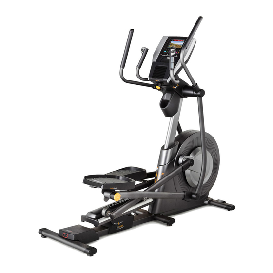
Model No. NTEVEL19813.0
Serial No.
USER'S MANUAL
Write the serial number in the space
above for reference.
Serial Number Decal
(on underside of frame)
CUSTOMER SERVICE
UNITED KINGDOM
Call: 08457 089 009
From Ireland: 053 92 36102
Website: www.iconsupport.eu
E-mail: csuk@iconeurope.com
Write:
ICON Health & Fitness, Ltd.
c/o HI Group PLC
Express Way
CASTLEFORD
WF10 5QJ
UNITED KINGDOM
AUSTRALIA
Call: 1800 993 770
E-mail: australiacc@iconfitness.com
Write:
ICON Health & Fitness
PO Box 635
WINSTON HILLS NSW 2153
AUSTRALIA
CAUTION
Read all precautions and instruc-
tions in this manual before using
this equipment. Keep this manual
for future reference.
www.iconeurope.com
Advertisement
Table of Contents

Related Manuals for NordicTrack COMMERCIAL 14.0


Summary of Contents for NordicTrack COMMERCIAL 14.0
- Page 1 Model No. NTEVEL19813.0 Serial No. USER’S MANUAL Write the serial number in the space above for reference. Serial Number Decal (on underside of frame) CUSTOMER SERVICE UNITED KINGDOM Call: 08457 089 009 From Ireland: 053 92 36102 Website: www.iconsupport.eu E-mail: csuk@iconeurope.com Write: ICON Health &...
-
Page 2: Table Of Contents
If a decal is missing or illegible, see the front cover of this manual and request a free replacement decal. Apply the decal in the location shown. Note: The decal(s) may not be shown at actual size. NORDICTRACK is a registered trademark of ICON IP, Inc. -
Page 3: Important Precautions
IMPORTANT PRECAUTIONS WARNING: To reduce the risk of burns, fire, electric shock, or injury to persons, read all important precautions and instructions in this manual and all warnings on your elliptical before using your elliptical. ICON assumes no responsibility for personal injury or property damage sus- tained by or through the use of this product. -
Page 4: Before You Begin
COMMERCIAL 14.0 elliptical. The manual. To help us assist you, note the product model ® COMMERCIAL 14.0 elliptical provides an impressive number and serial number before contacting us. The selection of features designed to make your workouts model number and the location of the serial number at home more effective and enjoyable. -
Page 5: Part Identification Chart
PART IDENTIFICATION CHART Use the drawings below to identify the small parts needed for assembly. The number in parentheses below each drawing is the key number of the part, from the PART LIST near the end of this manual. The number following the key number is the quantity needed for assembly. -
Page 6: Assembly
ASSEMBLY • Assembly requires two persons. • In addition to the included tool(s), assembly requires the following tools: • Place all parts in a cleared area and remove the one Phillips screwdriver packing materials. Do not dispose of the packing materials until you finish all assembly steps. - Page 7 3. Set the Rear Stabilizer (5) on the floor behind the Frame (1). Locate the wire tie in the Rear Stabilizer. See the inset drawing. Tie the end of the wire tie to the Sensor Wire Harness (155). Pull the other end of the wire tie until the Sensor Wire Harness (155) is routed through the Rear Stabilizer (5).
- Page 8 6. Identify the Lower Upright Cover (80), which has a large oval hole in it. Orient the Lower Upright Cover (80), the Shield Cover (75), and the Upright (4) as shown. Slide the Lower Upright Cover and the Shield Cover upward onto the Upright.
- Page 9 8. Tip: Avoid pinching the Main Wire Harness (110). Slide the Upright (4) onto the Frame (1). Attach Avoid pinching the Upright with seven M8 x 16mm Screws (72); the Main Wire do not fully tighten the Screws yet. Harness (110) Do not press the Shield Cover (75) into place yet.
-
Page 10: Using A Plastic Bag To Keep Your Fingers Clean
10. Using a plastic bag to keep your fingers clean, apply a generous amount of the included grease to the Arm Axle (35) and to two Wave Grease Washers (95). Insert the Arm Axle (35) into the Upright (4) and Grease center it. - Page 11 12. Tip: Avoid pinching the wires in the Right and Left Handlebars (83, 87). Attach the Right Handlebar (83) to the right side of the Console Bracket (62) with three M8 x 16mm Screws (72). Repeat this step with the Left Handlebar (87). Then, remove the packaging from the wires on the Right and Left Handlebars (83, 87).
- Page 12 14. Have a second person hold the Console (7) near the Console Bracket (62). Connect the Ground Wire (119) to the matching wire on the Console (7). Then, insert all of the Avoid pinching wires on the Console downward through the the wires indicated hole in the Console Bracket (62).
- Page 13 16. Slide the Lower Upright Cover (80) upward, and attach it to the Upright (4) with two M4 x 16mm Screws (104). 17. Attach the Accessory Tray Base (8) to the Upright (4) with two M4 x 16mm Screws (104). 18.
- Page 14 19. Press the Accessory Tray (37) into the Accessory Tray Base (8). 20. Press the Upper Upright Cover (91) onto the Lower Upright Cover (80).
- Page 15 21. Identify the Right Arm Upper Cover (67) and the Right Arm Lower Cover (68). Attach the Right Arm Upper Cover (67) to the Right Upper Body Leg (36) with an M4 x 16mm Screw (104). Then, press the Right Arm Lower Cover (68) onto the Right Arm Upper Cover (67).
-
Page 16: Elliptical
23. While a second person tips the elliptical to the left and holds it, attach a Stabilizer Cap (134) to the right side of the Frame (1) with two M4 x 16mm Screws (104). Next, tighten a Leveling Foot (92) into the Frame (1) in the indicated location. -
Page 17: The Chest Heart Rate Monitor
THE CHEST HEART RATE MONITOR HOW TO PUT ON THE HEART RATE MONITOR • Do not expose the heart rate monitor to direct sun- light for extended periods of time; do not expose it to The heart rate temperatures above 122° F (50° C) or below 14° F monitor consists of (-10°... -
Page 18: How To Use The Elliptical
HOW TO USE THE ELLIPTICAL HOW TO PLUG IN THE POWER CORD Follow the steps below to plug in the power cord. This product must be earthed. If it should malfunc- 1. Plug the indicated end of the power cord into the tion or break down, earthing provides a path of least socket on the frame. - Page 19 HOW TO MOVE THE ELLIPTICAL HOW TO ADJUST THE POSITIONS OF THE PEDALS Due to the size and weight of the elliptical, moving it requires two persons. Stand in front of the elliptical, Each pedal can be adjusted to several positions. To hold the upright, and place one foot against one of the adjust each pedal, lift the pedal and turn the pedal wheels.
- Page 20 HOW TO LEVEL THE ELLIPTICAL HOW TO EXERCISE ON THE ELLIPTICAL If the elliptical rocks slightly on your floor during use, To mount the elliptical, hold the upper body arms or turn one or both of the leveling feet beneath the rear the handlebars and step onto the pedal that is in the stabilizer until the rocking motion is eliminated.
- Page 21 CONSOLE DIAGRAM FEATURES OF THE CONSOLE The console also offers user-defined workouts that allow you to create your own workouts and store them The advanced console offers an array of features in memory for future use. designed to make your workouts more effective and enjoyable.
- Page 22 HOW TO TURN ON THE POWER HOW TO USE THE TOUCH SCREEN IMPORTANT: If the elliptical has been exposed to The console features a tablet with a full-color touch cold temperatures, allow it to warm to room tem- screen. The following information will help you become perature before you turn on the power.
- Page 23 HOW TO SET UP THE CONSOLE The browser will open to the iFit.com home page. Follow the prompts on the website to sign up for Before using the elliptical for the first time, set up the your iFit membership. If you have an activation console.
- Page 24 HOW TO USE THE MANUAL MODE 4. Follow your progress. 1. Touch the screen or press any button on the The console offers several display modes. The console to turn on the console. display mode that you select will determine which workout information is shown.
- Page 25 5. Measure your heart rate if desired. If the display does not show your heart rate, make sure that your hands are positioned as described. To use the chest heart rate monitor, see page Be careful not to move your hands excessively 17.
- Page 26 HOW TO USE AN ONBOARD WORKOUT IMPORTANT: The target rpm is intended only to provide motivation. Your actual pedaling speed 1. Touch the screen or press any button on the may be slower than the target rpm. Make sure console to turn on the console. to pedal at a speed that is comfortable for you.
- Page 27 HOW TO USE A SET-A-GOAL WORKOUT The workout will continue until you reach the goal that you set. A workout summary will appear on 1. Touch the screen or press any button on the the screen. After you view the workout summary, console to turn on the console.
- Page 28 HOW TO CREATE A USER-DEFINED WORKOUT To program a ramp incline level for the first seg- ment, simply adjust the incline of the ramp by 1. Touch the screen or press any button on the pressing the Ramp buttons. console to turn on the console. At the end of the first segment, the workout will See HOW TO TURN ON THE POWER on store the current resistance level and ramp incline...
- Page 29 HOW TO USE A USER-DEFINED WORKOUT pedals will automatically adjust to the resis- tance level programmed for the next segment 1. Touch the screen or press any button on the and the ramp will automatically adjust to the console to turn on the console. incline level programmed for the next segment.
- Page 30 HOW TO USE AN IFIT WORKOUT Note: Before some workouts will download, you must add them to your schedule on iFit.com. Note: To use an iFit workout, you must have access For more information about the iFit workouts, to a wireless network (see HOW TO USE THE please see www.iFit.com.
- Page 31 HOW TO USE THE EQUIPMENT SETTINGS MODE Note: If a passcode is enabled, the console will regularly ask for you to enter the passcode. The 1. Select the settings main menu. console will remain locked until the correct pass- code is entered. IMPORTANT: If you forget your passcode, enter the following master passcode Turn on the console and select the main menu (see steps 1 and 2 on page 24).
- Page 32 12. Enable or disable street view. The screen will show the progress of the update. When the update is complete, the elliptical will turn During some workouts, the screen may show a off and then turn back on. If it does not, press the map.
- Page 33 HOW TO USE THE WIRELESS NETWORK MODE An information box will ask if you want to connect to the wireless network. Touch the Connect button The console features a wireless network mode that to connect to the network or touch the Cancel but- allows you to set up a wireless network connection.
- Page 34 HOW TO USE THE SOUND SYSTEM HOW TO USE THE INTERNET BROWSER To play music or audio books through the console Note: To use the Internet browser, you must have sound system while you exercise, plug a 3.5 mm male access to a wireless network including a wireless to 3.5 mm male audio cable (not included) into the jack router (802.11b/g/n) with SSID broadcast enabled (hid-...
-
Page 35: Maintenance And Troubleshooting
MAINTENANCE AND TROUBLESHOOTING IMPORTANT: Servicing other than the procedures Next, see EXPLODED DRAWING A on page 41 and described below should be performed only by an EXPLODED DRAWING B on page 42. Remove the authorized service representative. M8 x 16mm Screw (72), the Axle Cover (53), and the M8 x 25mm Washer (149) from the upper end of the Inspect and tighten all parts of the elliptical regularly. - Page 36 HOW TO ADJUST THE REED SWITCH Loosen, but do not remove, the two M4 x 16mm Screws (104). Slide the Reed Switch (38) slightly If the console does not display correct feedback, the closer to or away from the Magnet (43). Then, retighten reed switch should be adjusted.
-
Page 37: Exercise Guidelines
EXERCISE GUIDELINES Burning Fat—To burn fat effectively, you must exer- WARNING: cise at a low intensity level for a sustained period of Before beginning this time. During the first few minutes of exercise, your or any exercise program, consult your physi- body uses carbohydrate calories for energy. - Page 38 SUGGESTED STRETCHES The correct form for several basic stretches is shown at the right. Move slowly as you stretch; never bounce. 1. Toe Touch Stretch Stand with your knees bent slightly and slowly bend forward from your hips. Allow your back and shoulders to relax as you reach down toward your toes as far as possible.
-
Page 39: Part List
PART LIST Model No. NTEVEL19813.0 R0713A Key No. Qty. Description Key No. Qty. Description Frame Roller Rear Stabilizer Cover Console Knob Ramp Axle Cover Upright Left Arm Upper Cover Rear Stabilizer Left Arm Lower Cover Front Stabilizer Upper Handlebar Cover Console Roller Arm/Pedal Arm Bushing Accessory Tray Base/Receiver... - Page 40 Key No. Qty. Description Key No. Qty. Description Idler Screw Left Pedal Adjustment Bracket M8 Locknut Pedal Arm Flex Bracket Ultrasonic Sensor Bracket Flex Bracket Cover M4 x 16mm Screw Left Pedal Plate M8 x 16mm Hex Screw Right Pedal Plate Small Pulley Spacer Pedal Plate Spring Large Standoff...
-
Page 41: Exploded Drawing
EXPLODED DRAWING A Model No. NTEVEL19813.0 R0713A... - Page 42 EXPLODED DRAWING B Model No. NTEVEL19813.0 R0713A...
- Page 43 EXPLODED DRAWING C Model No. NTEVEL19813.0 R0713A...
-
Page 44: Ordering Replacement Parts
ORDERING REPLACEMENT PARTS To order replacement parts, please see the front cover of this manual. To help us assist you, be prepared to provide the following information when contacting us: • the model number and serial number of the product (see the front cover of this manual) • the name of the product (see the front cover of this manual) • t he key number and description of the replacement part(s) (see the PART LIST and the EXPLODED DRAWING near the end of this manual) RECYCLING INFORMATION This electronic product must not be disposed of in municipal waste.
Need help?
Do you have a question about the COMMERCIAL 14.0 and is the answer not in the manual?
Questions and answers
Can the starting resistance be lowered by an adjustment. The resistance at level 1 is much to high for my wife who is just starting and is equivalent to level 4 on my old machine..
Yes, the starting resistance on the NordicTrack COMMERCIAL 14.0 can be adjusted. You can change the workout settings before starting, and during the workout, you can manually override the resistance level if it is too high or too low.
This answer is automatically generated