Table of Contents
Advertisement
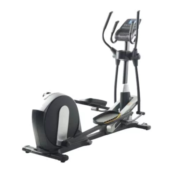
Model No. NTEVEL99813.0
Serial No.
USER'S MANUAL
Write the serial number in the space
above for reference.
Serial Number
Decal (under frame)
CUSTOMER SERVICE
UNITED KINGDOM
Call: 08457 089 009
From Ireland: 053 92 36102
Website: www.iconsupport.eu
E-mail: csuk@iconeurope.com
Write:
ICON Health & Fitness, Ltd.
c/o HI Group PLC
Express Way
CASTLEFORD
WF10 5QJ
UNITED KINGDOM
AUSTRALIA
Call: 1800 993 770
E-mail: australiacc@iconfitness.com
Write:
ICON Health & Fitness
PO Box 635
WINSTON HILLS NSW 2153
AUSTRALIA
CAUTION
Read all precautions and instruc-
tions in this manual before using
this equipment. Keep this manual
for future reference.
www.iconeurope.com
Advertisement
Table of Contents

Related Manuals for NordicTrack E 11.6 NTEVEL99813.0


Summary of Contents for NordicTrack E 11.6 NTEVEL99813.0
- Page 1 Model No. NTEVEL99813.0 Serial No. USER’S MANUAL Write the serial number in the space above for reference. Serial Number Decal (under frame) CUSTOMER SERVICE UNITED KINGDOM Call: 08457 089 009 From Ireland: 053 92 36102 Website: www.iconsupport.eu E-mail: csuk@iconeurope.com Write: ICON Health &...
-
Page 2: Table Of Contents
If a decal is missing or illegible, see the front cover of this manual and request a free replacement decal. Apply the decal in the loca- tion shown. Note: The decal(s) may not be shown at actual size. NORDICTRACK is a registered trademark of ICON IP, Inc. -
Page 3: Important Precautions
IMPORTANT PRECAUTIONS WARNING: To reduce the risk of burns, fire, electric shock, or injury to persons, read all important precautions and instructions in this manual and all warnings on your elliptical before using your elliptical. ICON assumes no responsibility for personal injury or property damage sus- tained by or through the use of this product. - Page 4 17. The heart rate monitor is not a medical 19. Keep your back straight while using the ellip- device. Various factors may affect the accu- tical; do not arch your back. racy of heart rate readings. The heart rate monitor is intended only as an exercise aid 20.
-
Page 5: Before You Begin
BEFORE YOU BEGIN Thank you for selecting the revolutionary reading this manual, please see the front cover of this NORDICTRACK E 11.6 elliptical. The E 11.6 elliptical manual. To help us assist you, note the product model ® provides an impressive selection of features designed number and serial number before contacting us. -
Page 6: Part Identification Chart
PART IDENTIFICATION CHART Use the drawings below to identify the small parts needed for assembly. The number in parentheses below each drawing is the key number of the part, from the PART LIST near the end of this manual. The number following the key number is the quantity needed for assembly. - Page 7 ASSEMBLY • Assembly requires two persons. • In addition to the included tool(s), assembly requires the following tools: • Place all parts in a cleared area and remove the one Phillips screwdriver packing materials. Do not dispose of the packing materials until you finish all assembly steps.
-
Page 8: Lower End Of The Wire Tie To The Upright Wire (60
3. Orient the Front Stabilizer (3) as shown. While a second person lifts the front of the Frame (1), attach the Front Stabilizer (3) with two M10 x 120mm Screws (100). 4. Identify and orient the Upright (5) and the Top Cover (23) as shown. - Page 9 5. Identify the Right Upper Body Arm (8) and the Right Upper Body Leg (6) and orient them as shown. Insert the Right Upper Body Arm (8) into the Right Upper Body Leg (6). Attach the Right Upper Body Arm (8) with three M8 x 45mm Bolts (104) and three M8 Locknuts (105).
- Page 10 7. Note: The Leveling Foot (41) may be preattached. With the help of a second person, place some of the packaging materials (not shown) under the Frame (1). Have the second person hold the Frame to prevent it from tipping while you complete this step.
- Page 11 9. See the upper drawing. Locate the Ramp Roller (92) on the Right Pedal Arm (12). Set the Ramp Roller (92) on the right side of the Ramp (43). See the lower drawing. Pull upward on the Latch (117) on the Right Pedal Arm (12). Press the Right Pedal Arm (12) onto the right Sleeve (136).
- Page 12 11. Apply grease to a Link Arm Axle (94) and to an M17 x 27mm Wave Washer (88). First, insert the Link Arm Axle (94) into the Right Upper Body Leg (6) from the side shown. Next, slide the M17 x 27mm Wave Washer (88) onto the Link Arm Axle.
- Page 13 13. Orient the Rear Upright Cover (24) as shown. Avoid pinching While a second person holds the Rear Upright the wires Cover (24) near the Upright (5), connect the receiver wire (A) to the Receiver Extension Wire (143). Tip: Avoid pinching the wires. Attach the Rear Upright Cover (24) to the Upright (5) with four M4 x 16mm Screws (93).
- Page 14 16. Identify the Right Rear Leg Cover (29). Attach the Right Rear Leg Cover (29) around the Right Upper Body Arm (8) by pressing it into the Right Front Leg Cover (30). Repeat this step on the other side of the elliptical.
- Page 15 18. Have a second person hold the Handlebar (10) near the Upright (5). See the inset drawing. Locate the Pulse Wire (135) in the Handlebar (10). Insert the Pulse Wire into the front of the Upright (5) and pull it out of the hole in the Upright as shown.
- Page 16 20. While a second person holds the Console (33) near the Handlebar (10), connect the wires on the Console to the Upright Wire (60), to the Receiver Extension Wire (143), and to the Pulse Wire (135). Avoid pinching the wires Insert the excess wire into the Handlebar (10) or into the Console (33).
-
Page 17: How To Use The Elliptical
HOW TO USE THE ELLIPTICAL HOW TO PLUG IN THE POWER CORD Follow the steps below to plug in the power cord. This product must be earthed. If it should malfunc- 1. Plug the indicated end of the power cord into the tion or break down, earthing provides a path of least socket on the frame. - Page 18 HOW TO FOLD AND UNFOLD THE ELLIPTICAL HOW TO MOVE THE ELLIPTICAL When the ellipti- To move the elliptical, first fold it as described at cal is not in use, the left. Next, stand in front of the elliptical, hold the the frame can upright, and place one foot against one of the wheels.
- Page 19 HOW TO EXERCISE ON THE ELLIPTICAL To dismount the elliptical, wait until the pedals come to a complete stop. Note: The elliptical does not have To mount the elliptical, hold the upper body arms and a free wheel; the pedals will continue to move until the flywheel stops.
- Page 20 CONSOLE DIAGRAM MAKE YOUR FITNESS GOALS A REALITY WITH Upload your workout results to the iFit cloud IFIT.COM and track your accomplishments. With your new iFit-compatible fitness equipment, you can use an array of features on iFit.com to make your Set calorie, time, or distance goals for your fitness goals a reality: workouts.
- Page 21 FEATURES OF THE CONSOLE HOW TO TURN ON THE POWER The advanced console offers an array of features IMPORTANT: If the elliptical has been exposed to cold temperatures, allow it to warm to room tem- designed to make your workouts more effective and perature before turning on the power.
- Page 22 HOW TO USE THE MANUAL MODE Calories (Cals.)—This display mode will show the approximate number of calories you have burned. 1. Begin pedaling or press any button on the console to turn on the console. Calories per Hour (Cals./Hr)—This display mode will show the approximate number of calories you See HOW TO TURN ON THE POWER on are burning per hour.
- Page 23 As you exercise, the workout intensity level bar rate, hold the handgrip heart rate monitor with your will indicate the approximate intensity level of your palms resting against the contacts. Avoid moving exercise. your hands or gripping the contacts tightly. When your pulse is detected, a heart symbol will flash in the display each time your heart beats, one or two dashes will appear, and then your heart...
- Page 24 HOW TO USE AN ONBOARD WORKOUT At the end of each segment of the workout, a series of tones will sound and the next segment of 1. Begin pedaling or press any button on the the profile will begin to flash. If a different resis- console to turn on the console.
- Page 25 HOW TO USE A SET-A-GOAL WORKOUT Note: The calorie goal is an estimate of the number of calories that you will burn during 1. Begin pedaling or press any button on the the workout. The actual number of calories that console to turn on the console.
- Page 26 HOW TO USE AN IFIT WORKOUT To compete in a race that you have previously scheduled, press the Compete button. You must have an iFit module to use an iFit workout. To re-run a recent iFit workout from your sched- To purchase an iFit module at any time, go to ule, first press the Track button.
- Page 27 6. Follow your progress with the display. HOW TO USE THE SOUND SYSTEM See step 4 on page 22. To play music or audio books through the console sound system while you exercise, plug a 3.5 mm male The My Trail tab will show a map of the trail you are to 3.5 mm male audio cable (not included) into the jack walking or running or it will show a track and the on the console and into a jack on your MP3 player,...
- Page 28 HOW TO CHANGE CONSOLE SETTINGS If no module is connected, the display will show the words NO IFIT MODULE. If no module is con- The console features a user mode that allows you to nected, go to step 10. view usage information, select a unit of measurement, 6.
-
Page 29: Maintenance And Troubleshooting
MAINTENANCE AND TROUBLESHOOTING Inspect and tighten all parts of the elliptical regularly. HOW TO ADJUST THE REED SWITCH Replace any worn parts immediately. If the console does not display correct feedback, the To clean the elliptical, use a damp cloth and a small reed switch should be adjusted. - Page 30 Next, loosen, but do not remove, the indicated M4 x Next, lift the Latch (117) on the underside of the Left 16mm Screw (93). Slide the Reed Switch (69) slightly Pedal Arm (13), and then lift the Left Pedal Arm off the toward or away from the Magnet (75).
-
Page 31: Exercise Guidelines
EXERCISE GUIDELINES Burning Fat—To burn fat effectively, you must exer- WARNING: cise at a low intensity level for a sustained period of Before beginning this time. During the first few minutes of exercise, your or any exercise program, consult your physi- body uses carbohydrate calories for energy. - Page 32 SUGGESTED STRETCHES The correct form for several basic stretches is shown at the right. Move slowly as you stretch; never bounce. 1. Toe Touch Stretch Stand with your knees bent slightly and slowly bend forward from your hips. Allow your back and shoulders to relax as you reach down toward your toes as far as possible.
- Page 33 NOTES...
-
Page 34: Part List
PART LIST Model No. NTEVEL99813.0 R0813B Key No. Qty. Description Key No. Qty. Description Frame Left Lift Arm Folding Frame Lift Axle Bushing Front Stabilizer Long Motor Axle Rear Stabilizer Short Motor Axle Upright Bumper Right Upper Body Leg #8 x 25mm Self-tapping Screw Left Upper Body Leg Upright Bushing Right Upper Body Arm... - Page 35 Key No. Qty. Description Key No. Qty. Description Anchored Zip Tie Outer Sleeve Bushing M8 x 16mm Screw Small Snap Ring M10 Locknut M8 Split Washer M8 x 45mm Bolt Short Spring Pin M8 Locknut Frame Cap Link Arm Bushing Inner Sleeve Bushing M10 x 25mm Screw Pulse Wire...
-
Page 36: Exploded Drawing
EXPLODED DRAWING A Model No. NTEVEL99813.0 R0813B... - Page 37 EXPLODED DRAWING B Model No. NTEVEL99813.0 R0813B...
- Page 38 EXPLODED DRAWING C Model No. NTEVEL99813.0 R0813B...
- Page 39 EXPLODED DRAWING D Model No. NTEVEL99813.0 R0813B...
- Page 40 ORDERING REPLACEMENT PARTS To order replacement parts, please see the front cover of this manual. To help us assist you, be prepared to provide the following information when contacting us: • the model number and serial number of the product (see the front cover of this manual) • the name of the product (see the front cover of this manual) • t he key number and description of the replacement part(s) (see the PART LIST and the EXPLODED DRAWING near the end of this manual) RECYCLING INFORMATION This electronic product must not be disposed of in municipal waste.
Need help?
Do you have a question about the E 11.6 NTEVEL99813.0 and is the answer not in the manual?
Questions and answers
The resistance change control no longer moves the resistance. Regardless of the resistance setting, the resistance is stuck on “1” from a resistance perspective, despite the monitor reading 15 or 22?