Table of Contents
Advertisement
Quick Links
Advertisement
Table of Contents

Related Manuals for Hanna Instruments Groline HI981413


Summary of Contents for Hanna Instruments Groline HI981413
- Page 1 HI981413 Nutrient Dosing System...
- Page 2 If you need additional technical information, do not hesitate to e‑mail us at tech@hannainst.com or view our contact list at www.hannainst.com. All rights are reserved. Reproduction in whole or in part is prohibited without the written consent of the copyright owner, Hanna Instruments Inc., Woonsocket, Rhode Island, 02895, USA.
-
Page 3: Table Of Contents
TABLE OF CONTENTS 1. PRELIMINARY EXAMINATION ....................4 2. SAFETY MEASURES ......................5 3. ABBREVIATIONS & CONVERSION CHARTS ................5 4. SPECIFICATIONS ......................... 6 4.1. HI981413 NUTRIENT DOSING SYSTEM ............... 6 4.2. HI30033 PROBE ....................... 7 5. DESCRIPTION ........................8 5.1. -
Page 4: Preliminary Examination
1. PRELIMINARY EXAMINATION Remove the instrument and accessories from the packaging and examine it carefully. For further assistance, please contact your local Hanna Instruments office or email us at tech@hannainst.com. Each HI981413 is available in multiple configurations: controller and probe - HI981413-00, kit for in-line mounting - HI981413-10, kit for flow cell mounting - HI981413-20. -
Page 5: Safety Measures
2. SAFETY MEASURES • Always disconnect the EC pump controller from power when making electrical connections. • Do not run other cables with the power cabling. • Do not touch the metallic part. Hot surface. 3. ABBREVIATIONS & CONVERSION CHARTS Light Emitting Diode American National Standard Taper Pipe Thread Inner Diameter... -
Page 6: Specifications
4. SPECIFICATIONS 4.1. HI981413 NUTRIENT DOSING SYSTEM 0.00 to 10.00 mS/cm 0 to 9900 ppm, depends on TDS factor i.e. with TDS factor 0.5, range 50 to 5000 ppm Range with TDS factor 0.7, range 70 to 7000 ppm Temperature* -5.0 to 105.0 °C (23.0 to 221.0 °F) 0.01 mS/cm 1 ppm Resolution... -
Page 7: Hi30033 Probe
• High & Low with enable or disable option • Triggered after 5 sec. if the controller records consecutive readings over or EC/TDS Alarms under threshold values • Level with enable or disable option • Overtime protection (1 to 180 min. or Off) Controller •... -
Page 8: Description
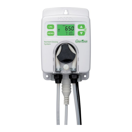
5. DESCRIPTION 5.1. GENERAL DESCRIPTION & INTENDED USE HI981413 Nutrient Dosing System is part of Hanna Instruments Groline family and features a durable EC controller with peristaltic dosing pump and a robust EC process sensor. The HI981413 has been designed to easily assimilate into a nutrient/fertilizer system to provide around the clock monitoring and adjustment of hydroponic nutrient solutions to ensure operational consistency. - Page 9 Main Features • Easy to read LCD display with intuitive, color-coded backlight • Automatic Temperature Compensation: all readings are compensated for variations in temperature. Temperature is displayed in °C or °F along with EC or TDS reading. The EC probe contains an integral temperature sensor to simplify installation.
-
Page 10: Functional & Display Description
5.2. FUNCTIONAL & DISPLAY DESCRIPTION Front Panel MENU Nutrient Dosing System 1. Keypad area 2. CAL key – Press calibration key to enter calibration mode. 3. MENU key – Press menu key to enter setup mode and move through the menu. Long press menu key to exit the menu and return to measurement. - Page 11 Internal Rear Panel Use a Phillips head screwdriver and remove the four screws, pull back the cover and remove it. To replace the rear panel, insert the four legs back in place and tighten the four screws that secure the panel to the enclosure.
- Page 12 Alarm Relay, Power & Level Sensor Normally Open ALARM RELAY OUTPUT Common SPDT 2.5 A / 230 Vac Normally Closed Pump controller not powered Alarm condition Working condition with no alarm Line – Hot connection POWER INPUT Protective Earth – Ground connection Neutral CLOSED OPEN...
- Page 13 Tubing fittings Sensor input Cable gland for level sensor cable Drainage opening Cable gland for alarm cable Cable gland for power cable Enclosure cap Cabling safety measures. Qualified personnel should perform wiring only. • A disconnect switch must be installed to break all current carrying conductors. Turn off power before working on conductors.
-
Page 14: Installation
6. INSTALLATION General Guidelines • Select controller location so that it is shielded from direct sunlight, dripping water and excess vibrations. • Select the nutrient injector point away from the sampling point to prevent triggering an alarm. • Keep flow rate as constant as possible for optimum sensor operation. •... - Page 15 Possible Installation Schemes for a Recirculating System In-Line Installation, Overview & Parts Table Below is an illustrated reference of a generic in-line installation scheme with the relevant components. The maximum pressure entering the flow cell system is 3 atm (44 psi). INJECTOR TANK FLOW...
- Page 16 Flow Cell Installation, Overview & Parts Table Below is an illustrated reference of a generic flow-cell installation scheme with the relevant components. The maximum pressure entering the flow cell system (P1) is 3 atm (44 psi) and decreases when it exits the flow-cell (P2).
- Page 17 Reservoir Immersion Installation Detailed below a representation of a reservoir immersion installation scheme together with the relevant components and the EC probe screwed into the threaded end of a user supplied pipe and fastened with a bracket. ” NPT Waterproof assembly Electrode holder tube Bracket Reservoir...
- Page 18 Mounting Recommendations for Saddle • Select required drill size. See table for dimension details. Drill Pipe • Place the upper part of the saddle (3) on top of the pipe (5) with the seal (4) placed over the hole. • Take the lower part of the saddle (6), together with inserted nuts (7) and align it under the upper part.
- Page 19 Installing Aspiration Filter The aspiration filter is used in the reagent tank to filter and prevent debris from entering the tubing. • Cut required length of aspiration tubing (flexible) to reach between peristaltic pump inlet and aspiration filter. • Place the end of tubing on the filter. •...
- Page 20 Flow Cell Installation In a flow cell configuration, the water flows from the inlet valve to the flow cell and returns in the line via the outlet valve. To prepare the inlet and outlet valve assemblies, as illustrated in the drawing: •...
- Page 21 Connecting the Probe to the Flow Cell • Remove the protective cap and verify if the O-ring (2) is in place. Note: The probe should be connected to the controller and calibrated before installation. • To avoid twisting the cable, unplug probe from socket temporarily while installing in flow cell. •...
-
Page 22: Setup
7. SETUP • Short press MENU key to move to next item in menu. • Long press MENU key to exit. • Press arrow keys to change the values. • Short press MENU key to automatically save modified values. Table below presents an overview of the menu with ranges and factory set defaults. Parameter Range / Option Default Settings... - Page 23 Parameter Range / Option Default Settings (Scrolled Message) En (English), ES (Spanish), Language Fr (French), Pt (Portuguese), En (English) nL (Dutch), dE (German) *Available range changes based upon other settings. High alarm must be set higher than low alarm. If low alarm was set 5.00 mS/cm (2500 ppm for 0.5 TDS factor) then high alarm range is 5.10 to 10.00 mS/cm (2510 to 9900 ppm, respectively).
- Page 24 Measurement Mode Option: Electrolytic Conductivity (EC) or Total Dissolved Solids (tdS) Measurement units will be mS/cm for EC and ppm for TDS measurements. Press the arrow keys to switch between the options. “MEASURE MODE” message is scrolled on the bottom of the LCD screen. Set point General: a set point is a threshold value that will trigger control if the measurement value crosses it.
- Page 25 Option: user selectable Press the arrow keys to set the value. “HYSTERESIS” or “PROPORTIONAL BAND” message is scrolled on the bottom of the LCD screen. Note: To enter Hysteresis / Band screen, pump control mode must be set as Auto. Startup Delay (Automatic Control Only) Option: user selectable (0 to 600s) Startup delay represents the delay to start dosing at power-on.
- Page 26 Flow Rate Option: selectable (0.5 to 3.5 L/hour, 0.13 to 0.92 G/hour) Press the arrow keys to change the values. When in On/Off automatic control mode, the displayed value represents the actual flow rate. When in Proportional automatic control mode, the displayed value represents a 100% flow rate. “FLOW RATE L/H”...
- Page 27 Low Alarm Option: Enabled (En) or disabled (diS) Press the arrow keys to switch between the options. “LOW ALARM” message is scrolled on the bottom of the LCD screen. Low Alarm Value Option: user selectable The range is influenced by the high-alarm value set (e.g. if high-alarm value is set as 8.00 mS/cm, low-alarm value can be set from 0.10 mS/cm and incremented up to 7.90 mS/cm).
- Page 28 Temperature Coefficient Option: The coefficient can be set between 0 to 2.4% / °C. A coefficient of 0.0%/°C is absolute conductivity. Press the arrow keys to change the values. “TEMPERATURE COEFFICIENT” message along with the set temperature unit is scrolled on the bottom of the LCD screen.
-
Page 29: Pump Control
8. PUMP CONTROL Pump control can be enabled, automatic control (AUTO) or disabled (off). See SETUP section for further details on how to enable or disable pump control. LCD backlight color indicates the pump control status: • green - automatic control or in View menu mode •... -
Page 30: Priming The Pump
On/O Control Lo control mode on the HI981413 Hi control mode on the HI981413 Pump running continuously Pump running continuously Pump status Pump status at the con gured ow rate at the con gured ow rate RUNNING RUNNING Hysteresis Hysteresis NOT RUNNING NOT RUNNING Measured... -
Page 31: Event Management
9. EVENT MANAGEMENT 9.1. ALARMS Alarms can be independently enabled or disabled in SETUP. Any event that activates the alarm turns automatic control Off, the alarm relay is deactivated and the LCD backlight is blinking red. The table below illustrates the conditions that will activate the alarm and deactivate the control pump. Alarm Description Alarm condition... -
Page 32: Warnings
9.2. WARNINGS Two types of warnings can be independently enabled or disabled in SETUP. If any of the warnings is active, the LCD backlight turns yellow. Screenshot for Warnings Description Terminate condition warning solution Press the up / down Startup delay Start up delay is active arrows at same time to restart pump. -
Page 33: Calibration
10. CALIBRATION 10.1. EC CALIBRATION HI981413 provides a digital calibration at the push of a button. Calibrate the probe frequently for improved accuracy. Also: • before in-line or flow cell installation • whenever the probe is replaced • after periodic maintenance Always use fresh calibration solutions and perform electrode maintenance prior to calibration (see ELECTRODE CARE &... -
Page 34: Process Ec & Tds Calibration
• When the standard is recognized, “RECOGNIZED” is scrolled at the bottom of the LCD display. “WAIT” is displayed until the reading is stable and the calibration is accepted. • If the standard solution is not recognized (either because the probe has not been placed in solution or the reading is outside accepted range), “---- WRONG”... - Page 35 EC process calibration is a single point calibration performed while the probe remains installed in the process. The value can be set ± 0.50 mS/cm around measured EC. • Press CAL key to enter calibration mode. When the first standard solution value is displayed, press one of the arrow keys to enter process calibration.
-
Page 36: Clear Calibration
• Press the arrow keys to adjust the process calibration value to the value determined with the reference meter. “PROCESS” message is scrolled on the bottom of the LCD screen. • Press CAL key to confirm the value. The “WAIT” message is followed by the “SAVE” message. •... -
Page 37: Measurement
11. MEASUREMENT • Power the controller. All LCD segments will be displayed for a few seconds. After initialization has been completed, the controller displays the measurement screen. • Plug the probe into the dedicated socket using the alignment notch to install properly. •... -
Page 38: Error Messages
12. ERROR MESSAGES The pump controller shows error messages when erroneous conditions appear and when measured values are outside the expected range. The information below provides an explanation of the errors, and recommended action to be taken. Error messages are displayed with red LED backlight. Probe is not connected. -
Page 39: Maintenance
13. MAINTENANCE 13.1. ELECTRODE CARE & MAINTENANCE Proper care and maintenance of the conductivity probe is essential for accurate readings. Cleaning, calibrating, and appropriate storage will extend the life of the probe. 1. As preventative maintenance measure, rinse the probe with tap water on a weekly basis. Monthly, a more thorough cleaning is advised. -
Page 40: Pump Tubing Replacement
13.2. PUMP TUBING REPLACEMENT Note: While replacing tubing, wear protective gloves and eye protection at all times. 1. Power off the controller. 2. Remove the plastic screw securing the transparent cover (2A) and the cover (2B). 3. Disconnect the tubing from the pump (3C). 4. - Page 41 6. Place the greased new peristaltic tube on the left side of the pump (6A) and rotate the pump rotor manually to the right (6B) until the tubing is on the pump. Fix the plastic holders on both sides (6C). 7.
-
Page 42: Accessories
14. ACCESSORIES ×2 10 m HI30033 EC/TDS/ 32'9" BL120-463 temperature probe Flow cell kit for with 2 m cable, Ø 63 mm pipe DIN Quick connect ×2 ×2 10 m 32'9" BL100-302 BL120-475 Pump cover Flow cell kit for with screw Ø... - Page 43 BL120-263 Injector saddle for BL120-301 Ø 63 mm pipe, Peristaltic pump rotor 1/2" thread BL120-275 Injector saddle for BL120-401 Ø 75 mm pipe, Flow cell valve 1/2" thread BL100-300 Peristaltic pump tubing kit (2 pcs.) Other Accessories HI7031-012 1413 μS/cm (1.41 mS/cm) solution (Groline), 120 mL HI7031-023 1413 μS/cm (1.41 mS/cm) solution (Groline), 230 mL HI7039-023...
-
Page 44: Certification
CERTIFICATION All Hanna Instruments conform to the CE European Directives. Disposal of Electrical & Electronic Equipment. The product should not be treated as household waste. Instead hand it over to the appropriate collection point for the recycling of electrical and electronic equipment which will conserve natural resources. -
Page 45: Warranty
If service is required, contact your local Hanna Instruments office. If under warranty, report the model number, date of purchase, serial number (engraved on the bottom of the meter) and the nature of the problem. - Page 46 MAN981413 05/21...
- Page 47 Hanna Instruments reserves the right to modify the design, construction or appearance of its products without advance notice.
- Page 48 World Headquarters Hanna Instruments Inc. Highland Industrial Park 584 Park East Drive Woonsocket, RI 02895 USA www.hannainst.com MAN981413 Printed in ROMANIA...
Need help?
Do you have a question about the Groline HI981413 and is the answer not in the manual?
Questions and answers