Table of Contents
Advertisement
Quick Links
Advertisement
Table of Contents

Related Manuals for Hanna Instruments HI922


Summary of Contents for Hanna Instruments HI922
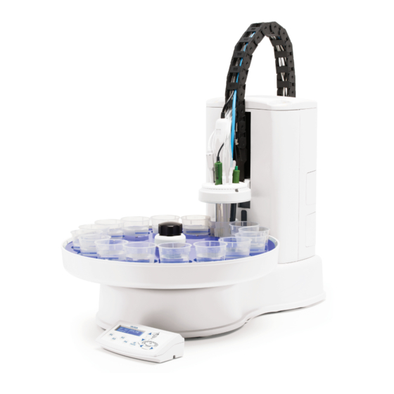
- Page 1 HI922 AUTOSAMPLER...
- Page 3 Dear Thank you for choosing a Hanna Instruments product. Customer, This manual has been written for the HI922 Autosampler. Please read this instruction manual carefully before using the instrument. The manual will provide you with all the necessary information on how to correctly setup the autosampler.
-
Page 4: Table Of Contents
1. INTRODUCTION ................................2. UNPACKING .................................. 3. SAFETY MEASURES............................... 4. INSTALLATION................................4.1. AUTOSAMPLER FRONT VIEW ............................4.2. AUTOSAMPLER REAR VIEW ............................4.3. AUTOSAMPLER SIDE VIEW ............................5. AUTOSAMPLER ASSEMBLY ............................5.1. BURETTE ASSEMBLY ..............................5.1.1. DISASSEMBLING THE BURETTE ..........................5.1.2. ASSEMBLING THE BURETTE ..........................5.2. -
Page 5: Introduction
For a complete list of Autosampler Components with part numbers and pictures, see page 19. If any of the items are missing or damaged, please notify your nearest Hanna Instruments Service Center. Note: Save all packing materials until you are sure that the instrument functions correctly. Any damaged or defective items must... -
Page 6: Safety Measures
3. SAFETY MEASURES The following safety measures must be followed: 1. Ensure that the titrator and autosampler are turned off before connecting or disconnecting pump assemblies. 2. Verify that the pumps and the attached tubing are assembled correctly. 3. Always check that the reagent and waste bottles are placed on a flat, stable surface and the titration beakers are placed in the tray. -
Page 7: Installation
4. INSTALLATION 4.1 AUTOSAMPLER FRONT VIEW 4.2 AUTOSAMPLER REAR VIEW... -
Page 8: Autosampler Side View
4.3. AUTOSAMPLER SIDE VIEW 5. AUTOSAMPLER ASSEMBLY 5.1. BURETTE ASSEMBLY 5.1.1. DISASSEMBLING THE BURETTE The aspiration and the dispensing tubes have fittings and tube protectors. The aspiration tube is mounted on the left side and the dispensing tube is mounted on the right side of the burette. To remove the dispensing tube follow these steps: •... -
Page 9: Assembling The Burette
5.1.2. ASSEMBLING THE BURETTE To attach the dispensing tube, follow these steps: Insert the flat-shaped end of the titrant tubing into the valve outlet (A) and screw the fitting clockwise to tighten. The highest of • the 9 cuts should be vertical in the final position. •... -
Page 10: Setting Up Dispenser Head
5.3. SETTING UP THE DISPENSER HEAD To set up the dispenser head follow these steps: • Release the clips from the cable carrier by using a flat head screwdriver. • Insert electrode, temperature sensor, stirrer, and aspiration tube (optional) into the dedicated holes in the electrode holder Push them down until they are in a stable position. -
Page 11: Connecting Pump Tubes
5.4. CONNECTING PUMP TUBES For Reagent Addition Operation: • Connect the dispensing tubing to the left side of the peristaltic pump. • Connect the reagent container tubing to the right side of the peristaltic pump. For Waste Aspiration Operation: • Connect the waste container tubing to the left side of the peristaltic pump. •... -
Page 12: Installing The Tray
5.5. INSTALLING THE TRAY • Place the tray on the turntable with Beaker 1 under the dispenser. Make sure the turntable mounting pins are aligned with the tray. • Lock the tray in place with the locking screw. Do not overtighten the locking screw! -
Page 13: Electrical Connections
5.6. ELECTRICAL CONNECTIONS • Connect the titrator to Titrator connector; • Connect the control panel to Control Panel connector; • Connect the overhead stirrer (optional) to Stirrer connector; • Connect a USB barcode reader (optional) to the USB port. -
Page 14: Operation
6. OPERATION 6.1. STATUS LIGHTS The status lights serve as a visual indication of the autosampler's current status: Idle, ready for commands Green (steady): Green (flashing): Running Yellow (steady): Firmware is updating Yellow (flashing): Paused, waiting for user action Red (flashing): Error Red (steady): Firmware corrupted. -
Page 15: Maintenance
7. MAINTENANCE 7.1. REPLACING PERISTALTIC PUMP TUBING Peristaltic pump tubing wears over time and will occasionally require replacement. To replace tubing: • Pull the clear plastic cover off of the pump (1) • Remove the plastic rotor and tubing (2) •... -
Page 16: Removing A Pump
WARNING! Turn off the autosampler and disconnect from the titrator before adding or removing pumps! Failure to do so could cause damage to the pump and/or autosampler. 7.2. REMOVING A PUMP • Remove the 4 screws holding the pump in the autosampler tower (1). •... -
Page 17: Upgrading Firmware
7.4. UPGRADING FIRMWARE HI922 firmware can be upgraded via the USB connector. The current firmware version is displayed on the control panel during boot-up and on the Autosampler Information screen. To upgrade the firmware: 1. Load the upgrade file into the root directory of a flash drive. Firmware files are named following “922v####.hex” format. -
Page 18: Technical Specification
8. TECHNICAL SPECIFICATIONS 5 x multi-purpose slots (titrant/reagent tubes) 3 x 12-mm electrodes slots Electrode Holder 1 x overhead stirrer slot 1 x temperature sensor slot 1 x aspiration tube slot magnetic stirrer (built-in) Stirrer overhead stirrer (optional) Temperature Sensor HI7662-AW (included) Peristaltic Pumps Up to three (Slots 1, 2 &... -
Page 19: Autosampler Components
9. AUTOSAMPLER COMPONENTS Communication Cable Autosampler HI920-933 HI922 - XYZ (HI932 to HI921/HI922) BNC Extension Cable (1 m) Control Panel HI920-931 HI920-922 Tray Locking Screw Reference Extension Cable (1 m) HI920-960 HI920-932 Electrode Holder 16 Beaker Tray, 60 mm dia. - Page 20 Peristaltic Pump with dispensing tubing Membrane Pump Complete Tubing Set HI920-103 HI920-212 Peristaltic pump with aspiration tubing TYGON Tube (5 m) HI920-104 HI920-290 Membrane Pump with tubing Overhead Stirrer + HI920-113 3 propellers HI930301 Replacement Propellers Replacement Cap and Rotor for Peristaltic Pump (3 pcs.) HI920-201...
- Page 21 Certification All Hanna Instruments conform to the CE European Directives. Disposal of Electrical & Electronic Equipment. The product should not be treated as household waste. Instead hand it over to the appropriate collection point for the recycling of electrical and electronic equipment which will conserve natural resources.
- Page 22 If the repair is not covered by the warranty, you will be notified of the charges incurred. If the instrument is to be returned to Hanna Instruments, first obtain a Returned Goods Authorization (RGA) number from the Technical Service department and then send it with shipping costs prepaid.
- Page 24 World Headquarters Hanna Instruments Inc. Highland Industrial Park 584 Park East Drive Woonsocket, RI 02895 USA www.hannainst.com Local Office Hanna Instruments Inc. Highland Industrial Park 584 Park East Drive Woonsocket, RI 02895 USA Phone: 800.426.6287 Fax: 401.765.7575 e-mail: tech@hannainst.com...
Need help?
Do you have a question about the HI922 and is the answer not in the manual?
Questions and answers