Table of Contents
Advertisement
Quick Links
Advertisement
Table of Contents

Related Manuals for Hanna Instruments Groline HI981412


Summary of Contents for Hanna Instruments Groline HI981412
- Page 1 HI981412 pH Dosing System...
- Page 2 If you need additional technical information, do not hesitate to e‑mail us at tech@hannainst.com or view our contact list at www.hannainst.com. All rights are reserved. Reproduction in whole or in part is prohibited without the written consent of the copyright owner, Hanna Instruments Inc., Woonsocket, Rhode Island, 02895, USA.
-
Page 3: Table Of Contents
TABLE OF CONTENTS 1. PRELIMINARY EXAMINATION ....................4 2. SAFETY MEASURES ......................5 3. ABBREVIATIONS ........................ 5 4. SPECIFICATIONS ......................... 6 4.1. HI981412 pH DOSING SYSTEM ................. 6 4.2. HI10063 pH & TEMPERATURE PROBE ................ 7 5. DESCRIPTION ........................8 5.1. -
Page 4: Preliminary Examination
1. PRELIMINARY EXAMINATION Remove the instrument and accessories from the packaging and examine it carefully. For further assistance, please contact your local Hanna Instruments Office or email us at tech@hannainst.com. Each HI981412 is available in multiple configurations: controller and probe - HI981412-00, kit for in-line mounting - HI981412-10, kit for flow cell mounting - HI981412-20. -
Page 5: Safety Measures
2. SAFETY MEASURES • Always disconnect the pH pump controller from power when making electrical connections. • Do not run other cables with the power cabling. • Do not touch the metallic part. Hot surface. 3. ABBREVIATIONS Food and Drug Administration Light Emitting Diode Polyethylene Polyvinyl Chloride... -
Page 6: Specifications
4. SPECIFICATIONS 4.1. HI981412 pH DOSING SYSTEM 0.00 to 14.00 pH Range * -5.0 to 105.0 °C (23.0 to 221.0 °F) 0.01 pH Resolution 0.1 °C (0.1 °F) Accuracy ±0.10 pH @ 25 °C (77 °F) ±0.5 °C (±0.9 °F) •... -
Page 7: Hi10063 Ph & Temperature Probe
• External switches can be attached to stop the pump and activate the Level sensor input alarm (low reagent level) when the switch is open and level alarm is (Digital input) configured in Setup • Galvanic isolation Power supply 100 - 240 Vac, 50/60 Hz Power consumption 15 VA Environment... -
Page 8: Description
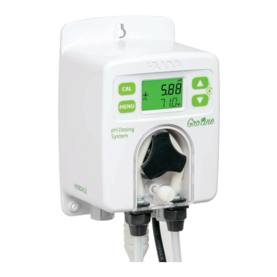
5.1. GENERAL DESCRIPTION & INTENDED USE HI981412 pH Dosing System is part of Hanna Instruments Groline family and features a pH controller with peristaltic dosing pump and a process sensor. Maintaining the correct pH of plant soil or hydroponic nutrient solution is an ongoing task. Macro and micro nutrients as well as calcium and magnesium bloom boosters require the correct pH for absorption into the plants root system. -
Page 9: Functional & Display Description
5.2. FUNCTIONAL & DISPLAY DESCRIPTION Front Panel MENU pH Dosing System 1. Keypad area 2. CAL key – Press calibration key to enter calibration mode. 3. MENU key – Press menu key to enter setup mode and move through the menu. Long press menu key to exit the menu and return to measurement. - Page 10 Internal Rear Panel Use a Phillips head screwdriver and remove the four screws, pull back the cover and remove it. To replace the rear panel, insert the four legs back in place and tighten the four screws that secure the panel to the enclosure.
- Page 11 Alarm Relay, Power & Level Sensor Normally Open ALARM RELAY OUTPUT Common SPDT 2.5 A / 230 Vac Normally Closed Pump controller not powered Alarm condition Working condition with no alarm Line POWER INPUT Protective Earth Neutral Low level sensor in tank LEVEL SENSOR...
- Page 12 Position Description Tubing fittings Sensor input Cable gland for level sensor Drainage opening Cable gland for alarm cable Cable gland for power cable Enclosure cap Cabling safety measures. Qualified personnel should perform wiring only. • A disconnect switch must be installed to break all current carrying conductors. Turn off power before working on conductors.
-
Page 13: Installation
6. INSTALLATION General Guidelines • Select controller location so that it is shielded from direct sunlight, dripping water and excess vibrations. • Select the acid-dosing injector point away from the sampling point to prevent acids from damaging the probe or triggering an alarm. •... - Page 14 Possible Installation Schemes for a Recirculating System In-Line Installation, Overview & Parts Table Below is an illustrated reference of a generic in-line installation scheme with the relevant components. Note: Injectors prevent back flow into reagent tank. Position Description pH probe Flexible PVC tubing Rigid PE tubing Aspiration filter...
- Page 15 Flow Cell Installation, Overview & Parts Table Below is an illustrated reference of a generic flow-cell installation scheme with the relevant components. The maximum pressure of the flow cell system is 3 atm (44 psi). Position Description Position Description 1/2” to 6 mm adapter for tubing pH probe Valve to control flow-cell flow Flow cell and adapter...
- Page 16 Reservoir Immersion Installation Detailed below a representation of a reservoir immersion installation scheme together with the relevant components and the pH probe screwed into the threaded end of a user supplied pipe and fastened with a bracket. Position Description Electrode holder tube Bracket (user supplied) Reservoir Electrode...
- Page 17 Mounting Recommendations for Saddle • Select required drill size. See table for dimension details. Drill Pipe • Place the upper part of the saddle (3) on top of the pipe (5) with the seal (4) placed over the hole. • Take the lower part of the saddle (6), together with inserted nuts (7) and align it under the upper part.
- Page 18 Installing Aspiration Filter The aspiration filter is used in the reagent tank to filter and prevent debris from entering the tubing. • Cut required length of aspiration tubing (flexible) to reach between peristaltic pump inlet and aspiration filter. • Place the end of tubing on the filter. •...
- Page 19 Flow Cell Installation In a flow cell configuration, the water flows from the inlet valve to the flow cell and returns in the line via the outlet valve. To prepare the inlet and outlet valve assemblies, as illustrated in the drawing: •...
- Page 20 Connecting the Probe to the Pump Controller (Flow Cell Configuration) • Remove the protective cap and verify if the O-ring (2) is in place. • The probe should be connected to the controller and calibrated before installation. • To avoid twisting the cable, unplug probe from socket temporarily while installing in flow cell. •...
-
Page 21: Setup
7. SETUP • Short press MENU key to move to next item in menu. • Long press MENU key to exit. • Press arrow keys to change the values. • Short press MENU key to automatically save modified values. Table below presents an overview of the menu with ranges and factory set defaults. Parameter Range / Option Default settings... - Page 22 Control Option: Auto or Off (oFF) to enable or disable the control With disabled option oFF, the control is off. Press one of the arrow keys for the controller settings to change from Auto to oFF and vice versa. To run a ten-seconds pump test, long press the arrow keys together until the pump starts to run. “CONTROL”...
- Page 23 Note: To enter Set point screen, pump control mode must be set as Auto. Hysteresis / Proportional Band Hysteresis (On/Off Control only) On/Off control action turns the dosing On or Off based on a previously assigned set point. The pump status (running or not running) changes depending on pH changes.
- Page 24 Overtime Alarm Option: user selectable (off, 1 to 180 minutes) Press the arrow keys to change the time values. To disable the alarm, select Off. “OVERTIME ALARM MIN” message is scrolled on the bottom of the LCD screen. Note: To enter Overtime alarm screen, pump control mode must be set as Auto. Flow Rate Option: user selectable (0.5 to 3.5 L/hour, 0.13 to 0.92 G/hour) Press the arrow keys to change the values.
- Page 25 High Alarm Value Option: user selectable The range is influenced by the low-alarm value set (e.g. if low-alarm value is set as 5 pH, high-alarm value can be set from 5.10 pH and incremented up to 14.00 pH). “HIGH ALARM VALUE” message is scrolled on the bottom of the LCD screen. Note: The user can set the high-alarm value with high-alarm option enabled only.
- Page 26 Flow Rate Measurement Unit Option: Liter/hour (L.H) or Gallon/hour (GAL.H) Press the arrow keys to switch between the options. Languages Option: select from: En (English), ES (Spanish), Fr (French), Pt (Portuguese), nL (Dutch), dE (German) Press the arrow keys to change the language. ”LANGUAGE”...
-
Page 27: Pump Control
8. PUMP CONTROL Pump control can be enabled, automatic control (AUTO) or disabled (off). See SETUP section for further details on how to enable or disable pump control. LCD backlight color indicates the pump control status: • green - automatic control or in View menu mode •... -
Page 28: Priming The Pump
On/O Control Hi control mode on the HI981412 Lo control mode on the HI981412 Pump running continuously Pump running continuously Pump status Pump status at the con gured ow rate at the con gured ow rate RUNNING RUNNING Hysteresis Hysteresis NOT RUNNING NOT RUNNING Measured... -
Page 29: Events Management
9. EVENTS MANAGEMENT 9.1. ALARMS Alarms can be independently enabled or disabled in SETUP. Any event that activates the alarm turns automatic control Off, the alarm relay is deactivated and the LCD backlight is blinking red. The table below illustrates the conditions that will activate the alarm and deactivate the control pump. Alarm Description Alarm condition... -
Page 30: Warnings
9.2. WARNINGS Two types of warnings can be independently enabled or disabled in SETUP. If any of the warnings is active, the LCD backlight turns yellow. Screenshot for Warnings Description Terminate condition warning solution Press the up / down arrows at same time to restart pump. -
Page 31: Calibration
10. CALIBRATION 10.1. pH CALIBRATION HI981412 provides a digital calibration at the push of a button. Calibrate the probe frequently for improved accuracy. Also: • before in-line or flow cell installation • whenever the probe is replaced • after periodic maintenance Always use fresh calibration buffers and perform electrode maintenance prior to calibration (see ELECTRODE CARE &... - Page 32 • If the buffer is not recognized (either because the pH electrode has not been placed in solution or the reading is outside accepted range), “---- WRONG” message is displayed along with CAL tag blinking. • After pH 4.01 or 10.01 buffer is accepted, the “SAVE” message is displayed and the controller returns to measurement mode.
-
Page 33: Process Ph Calibration
• The “CAL” tag is displayed in measurement mode. • If the buffer is not recognized, “---- WRONG” message is displayed. It is recommended to change the solution and / or clean the electrode. • Press CAL key to exit calibration. Note: If high accuracy is required, a two-point calibration is recommended. -
Page 34: Clear Calibration
• Press CAL key to confirm the value (the “SAVE” message appears for a few seconds). • Press MENU key to exit without saving and return to measurement mode (the “ESC” message is displayed for a few seconds). 10.3. CLEAR CALIBRATION •... -
Page 35: Measurement
11. MEASUREMENT • Power the controller. All LCD segments will be displayed for a few seconds. After initialization has been completed, the controller displays the measurement screen. • Plug the probe into the dedicated socket using the alignment notch to install properly. •... -
Page 36: Error Messages
12. ERROR MESSAGES The pump controller shows error messages when erroneous conditions appear and when measured values are outside the expected range. The information below provides an explanation of the errors, and recommended action to be taken. Error messages are displayed with red LED backlight. Probe is not connected. -
Page 37: Maintenance
13. MAINTENANCE 13.1. ELECTRODE CARE & MAINTENANCE Proper care and maintenance of the pH probe is essential for accurate readings. Cleaning, calibrating, and appropriate storage will extend the life of the probe. • Remove the electrode protective cap. Do not be alarmed if any salt deposits are present, this is normal. - Page 38 4. Starting from the left side of the pump, grab the peristaltic pump tubing and rotate the pump rotor manually to the right, until the tubing is removed. 5. Grease the new peristaltic pump tubing and place it on the left side of the pump. Manually rotate the pump rotor to the right until the tubing is on the pump.
-
Page 39: Accessories
14. ACCESSORIES HI10063 pH/temp. BL100-302 probe with Pump cover 2 m cable, DIN with screw Quick connect BL100-410 BL100-411 Flow cell for Flow cell panel HI981412 BL100-450 BL100-463 Flow cell kit for Flow cell kit for Ø 50 mm pipe Ø... - Page 40 BL120-275 BL100-300 Injector saddle for Peristaltic pump Ø 75 mm pipe, tubing kit 1/2” thread BL120-301 BL120-401 Peristaltic pump Flow cell valve rotor Other Accessories HI70004G pH 4.01 buffer sachet (GroLine), 20 mL (25 pcs.) HI70007G pH 7.01 buffer sachet (GroLine), 20 mL (25 pcs.) HI70010G pH 10.01 buffer sachet (GroLine), 20 mL (25 pcs.) HI7004-050...
-
Page 41: Certification
CERTIFICATION All Hanna Instruments conform to the CE European Directives. Disposal of Electrical & Electronic Equipment. The product should not be treated as household waste. Instead hand it over to the appropriate collection point for the recycling of electrical and electronic equipment which will conserve natural resources. -
Page 42: Recommendations For Users
If service is required, contact your local Hanna Instruments Office. If under warranty, report the model number, date of purchase, serial number (engraved on the bottom of the meter) and the nature of the problem. - Page 43 Hanna Instruments reserves the right to modify the design, construction or appearance of its products without advance notice.
- Page 44 World Headquarters Hanna Instruments Inc. Highland Industrial Park 584 Park East Drive Woonsocket, RI 02895 USA www.hannainst.com MAN981412 Printed in ROMANIA...
Need help?
Do you have a question about the Groline HI981412 and is the answer not in the manual?
Questions and answers