Table of Contents
Advertisement
Quick Links
Advertisement
Table of Contents

Related Manuals for Hanna Instruments HI 921


Summary of Contents for Hanna Instruments HI 921
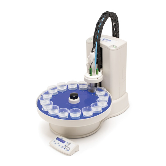
- Page 1 INSTRUCTION MANUAL HI 921 AUTOSAMPLER Revision www.hannainst.com...
- Page 2 INSTRUCTION MANUAL...
- Page 3 For information on the autosampler functinality see Chapter 12 in the HI 902 Potentiometric Titrator Manual. © 2015 Hanna Instruments All rights are reserved. Reproduction in whole or in part is prohibited without the written consent of the copyright owner, Hanna Instruments Inc., 584 Park East Drive, Woonsocket, Rhode Island 02895, USA.
-
Page 4: Table Of Contents
INSTRUCTION MANUAL Contents INTRODUCTION ......................5 UNPACKING ......................5 SAFETY MEASURES ....................6 INSTALLATION DIAGRAM ..................7 SETUP ........................8 Install the Burette Dispensing Tube ..............8 Attach the Cable Carrier .................. 9 Set Up the Dispenser Head ................1 0 Connect the Pump Tubes ................1 1 Install the Tray ..................... -
Page 5: Introduction
INTRODUCTION The HI 921 Autosampler is designed automate a wide variety of potentiometric titrations in conjunction with the HI 902C Automatic Titrator. The HI 921 allows users to perform high speed analysis while obtaining accurate results with minimal user interference. -
Page 6: Safety Measures
INSTRUCTION MANUAL SAFETY MEASURES The following safety measures must be followed: 1. Never connect or disconnect the pumps assemblies from the Autosampler and Titrator when they are turned on. 2. Verify that the pumps and the attached tubing are assembled correctly. 3. -
Page 7: Installation Diagram
INSTRUCTION MANUAL INSTALLATION DIAGRAM Rear View Front View Side View... -
Page 8: Setup
INSTRUCTION MANUAL SETUP 1. Install the Burette Dispensing Tube The dispensing tube is mounted on the right side of the burette. This tube needs to be replaced with a longer one in order to reach the Autosampler. To remove the dispensing tube follow these steps: •... -
Page 9: Attach The Cable Carrier
INSTRUCTION MANUAL 2. Attach the Cable Carrier To attach the cable carrier remove the three (3) screws from the top rear panel (A). Align the screw holes on the cable carrier (B) to the rear panel and replace the screws. -
Page 10: Set Up The Dispenser Head
INSTRUCTION MANUAL 3. Set Up the Dispenser Head • Insert electrode, temperature sensor, stirrer, and aspiration tube (optional) into the dedicated holes in the electrode holder. Push them down until they are in a stable position. • Insert burette and auxiliary tubing into the appropriate holders. •... -
Page 11: Connect The Pump Tubes
INSTRUCTION MANUAL Connect the Pump Tubes... -
Page 12: Install The Tray
INSTRUCTION MANUAL 5. Install the Tray • Place the tray on the turntable with Beaker 1 under the dispenser. Make sure the turntable mounting pins are aligned with the tray. • Lock the tray in place with the locking screw. Do not over-tighten the locking screw! -
Page 13: Electrical Connections
INSTRUCTION MANUAL Electrical Connections • Connect the HI 902C titrator to the 5-pin threaded connector. • Connect the control panel to the 4-pin threaded connector. • Connect the overhead stirrer (optional) to the 4-pin mini-DIN connector. • Connect a USB barcode reader (optional) to the USB slot. -
Page 14: Operation
INSTRUCTION MANUAL OPERATION Status Lights The status light serve as a visual indication of the current state of the Autosampler: Green (steady): Idle, ready for commands. Green (flashing): Running. Yellow (steady): Firmware is updating. Yellow (flashing): Paused, waiting for user action. Red (flashing): Error. -
Page 15: Maintenance
INSTRUCTION MANUAL MAINTENANCE Replacing Peristaltic Pump Tubing Peristaltic pump tubing wears over time and will occasionally require replacement. To replace tubing: • Pull the clear plastic cover off of the pump (1). • Remove the plastic rotor and tubing (2). •... - Page 16 INSTRUCTION MANUAL WARNING! Turn off the Autosampler and disconnect from the Titrator before adding or removing pumps! Failure to do so could cause damage to the pump and/or Autosampler. Removing a Pump • Remove the 4 screws holding the pump in the Autosampler tower (1). •...
-
Page 17: Upgrading Firmware
1. Load the upgrade file into the root directory of a flash drive. Firmware files are named with the format “ 921v####.hex ”. 2. Power off the HI 921 Autosampler using the power switch, but leave the cable connected to the HI 902 Titrator. -
Page 18: Technical Specifications
INSTRUCTION MANUAL TECHNICAL SPECIFICATIONS Electrode Holder Slots 3 x 12-mm Electrodes Slots 1 Temperature Sensor Slot 1 Aspiration Tube Slot 5 Multi - purpose Slots (titrant/reagent tubes) 1 Overhead Stirrer Slot Temperature Sensor HI 7662-A (Included) Stirrer Magnetic Stirrer (Built in) Overhead Propeller Stirrer (optional) Peristaltic Pumps Up to 3 (Slots 1, 2 &... -
Page 19: Autosampler Components
INSTRUCTION MANUAL AUTOSAMPLER COMPONENTS Comunication Cable Autosampler HI 920-930 HI 921 - XY BNC Extension Cable (1 m) Control Panel HI 920-931 HI 920-921 Reference Extension Cable Tray Locking Screw (1 m) HI 920-960 HI 920-932 16 Beaker Tray, 60 mm dia. - Page 20 INSTRUCTION MANUAL Membrane Pump Complete Persitaltic Pump with Tubing Set dispensing tubing HI 920-212 HI 920-101 TYGON Tube (5 m) Persitaltic Pump with HI 920-290 aspiration tubing HI 920-102 Overhead Stirrer Membrane Pump with HI 920-301 tubing HI 920-111 Replacement Propellers Replacement Cap and (3 pcs.) Rotor for Peristaltic Pump...
- Page 21 INSTRUCTION MANUAL...
- Page 22 INSTRUCTION MANUAL...
Need help?
Do you have a question about the HI 921 and is the answer not in the manual?
Questions and answers