Table of Contents
Advertisement
Quick Links
Advertisement
Table of Contents

Subscribe to Our Youtube Channel
Related Manuals for Auto Crane 3203H


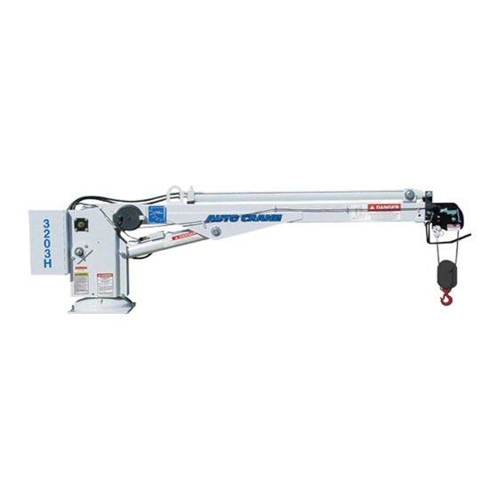
Summary of Contents for Auto Crane 3203H
- Page 1 3203H OWNERS MANUAL Manual No. 999954 Rev. 9/2/2003 Serial No. __________________ Mailing Address: P.O. Box 580697 Tulsa, OK 74158-0697 Physical Address: Phone (918) 836-0463 4707 N. Mingo Rd. Fax (918) 834-5979 Tulsa, OK 74117-5904 http://www.autocrane.com...
- Page 3 Serial No.: Date Product Delivered: Date Processed:* VIN # * For Auto Crane use only ONE REGISTRATION FORM PER UNIT (CRANE OR BODY) Registration form must be mailed or faxed within 15 days of customer installation. Mail to: Warranty Department Auto Crane Company P.O.
- Page 5 3203H SERIES OWNER’S MANUAL – REVISION RECORD Section(s) Revision Description of Change Date Page(s) 09/02/03 Last page New 2-year warranty policy to replace 1-year warranty policy...
- Page 7 ♦ Attempt to lift or drag a load from the side! The boom can fail far below its rated capacity. ♦ Weld, modify, or use unauthorized components on any Auto Crane unit! This will void any warranty or liability. Also failure of the crane may result.
-
Page 9: Table Of Contents
3203H SERIES - OWNER'S MANUAL TABLE OF CONTENTS PAGE INTRODUCTION .......... -
Page 11: Introduction
Auto Crane has incorporated several safety features in the knowledgeable Customer Service Department. In most cases, 3203H Series cranes for your protection. The choice of an equipment problem is solved via phone conversation with materials and the design of the electrical system minimizes our customer service department. - Page 12 GENERAL SPECIFICATIONS 3203H Dimensions Cable Width: 24 in (.61 m) 62 ft (18.9 m) of 7/32" diameter aircraft quality 23.25 (.59 m) single line breaking strength of 5,600 lbs (2,540 Height: 27.25 in (.69 m) 31.31 in (.80 m) kg).
-
Page 13: Operating Practices & Warnings
15. ALWAYS store outriggers before road travel. WARNING! Auto Crane Company remote controlled, stiff boom cranes are not designed or intended to be used for any applications involving the lifting or moving of personnel. -
Page 14: Operation Of Unit / Outriggers
(or in 12. Store pendant control on proper location (in cab or on park for automatic transmissions). Activate any crane power switches. For Auto Crane units requiring crane). battery and hydraulic operation, engage emergency 13. -
Page 15: Qualifications For Operators
QUALIFICATIONS FOR AND CONDUCT OF OPERATORS AND OPERATING PRACTICES OPERATORS 8 In addition to the above listed requirements, the operator shall: A. Demonstrate the ability to comprehend and interpret 1 Crane operation shall be limited to personnel with the all labels, operator's manuals, safety codes and other following minimum qualifications: information pertinent to correct crane operations. - Page 16 QUALIFICATIONS FOR AND CONDUCT OF OPERATORS AND OPERATING PRACTICES promptly to the appointed person, and shall also 1. there is no sudden acceleration or notify the next operator. deceleration of the moving load. 2. load, boom or other parts of the crane do 16 All controls shall be tested by the operator at the start not contact any obstruction.
- Page 17 QUALIFICATIONS FOR AND CONDUCT OF OPERATORS AND OPERATING PRACTICES MISCELLANEOUS 25 In transit with no load and boom lowered the clearance shall be specified in Table 1. OPERATING NEAR ELECTRICAL POWER 26 A qualified signalperson shall be assigned to observe LINES the clearance and give warning before approaching the above limits.
-
Page 18: Inspection, Testing, & Maintenance
INSPECTION, TESTING AND MAINTENANCE GENERAL H. hydraulic system for proper oil level and leaks daily INSPECTION CLASSIFICATION I. tires for recommended inflation pressure, cuts and 1 Initial inspection. Prior to initial use, all new, altered, loose wheel nuts modified or extensively repaired cranes shall be J. - Page 19 INSPECTION, TESTING AND MAINTENANCE GENERAL 13 Hydraulic and pneumatic pumps and motors 17 Labels are to be in place and legible. inspection. CRANES NOT IN REGULAR USE A. loose bolts or fasteners 18 A crane which has been idle for a period of over one B.
- Page 20 INSPECTION, TESTING AND MAINTENANCE GENERAL C. control systems 22 Test loads shall not exceed 110% of the manufac- turer's load ratings. 29 Repairs or replacements shall be provided as needed for operation. 23 Written reports shall be maintained showing test procedures and confirming the adequacy of repairs.
- Page 21 INSPECTION, TESTING AND MAINTENANCE GENERAL discovered, the rope shall either be 2. sections of the rope at or near terminal removed from service or given as ends where corroded or broken wires may inspection. protrude B. Care shall be taken when inspecting sections of rapid ROPE REPLACEMENT deterioration such as flange points, crossover points, and repetitive pickup points on drums.
- Page 22 INSPECTION, TESTING AND MAINTENANCE GENERAL H. Replacement rope shall have a strength rating at 39 Before cutting a rope, seizing shall be placed on each least as great as the original rope furnished or side of the place where the rope is to be cut to prevent recommended by the crane manufacturer.
- Page 23 Auto Crane units, up to 2,400 pound ratings, use deterioration of wire line cable that it is not 3/16 inch diameter galvanized pre-formed 7 x 19 possible to determine a definite life expectancy. aircraft cable. This cable has a working strength, Some of these factors are: when new, of 4,200 pounds.
- Page 24 DANGER, ELECTROCUTION HAZARD SD-4 DANGER, OPERATION INSTRUCTIONS SD-5 DANGER, OPERATOR TRAINING SD-6 WARNING, LOAD SENSOR TAMPERING SD-7 AUTO CRANE COMPANY PO BOX 580697, TULSA, OK 74158-0697 4707 N. MINGO ROAD, TULSA, OK 74117-5904 Phone (918) 836-0463. Fax (918) 834-5979 SFTYDCL 8/02 1-7.0.0...
-
Page 25: Safety Decal Section
SAFETY DECAL SECTION PART NO.: 040517 DECAL: STAY CLEAR OF BOOM FUNCTION: To inform the operator of the hazard of proximity or contact with the crane boom during operation. QUANTITY Both sides of crown PLACEMENT (see page 1-7.3.0, Item 1) FIG. - Page 26 SAFETY DECAL SECTION PART NO.: 040529 QUANTITY DECAL: ELECTROCUTION HAZARD Both sides of end of lower boom PLACEMENT FUNCTION: To inform the operator of the (see page 1-7.3.0, Item 16) hazard involved with contacting electrical power lines with crane boom. FIG.
- Page 27 SAFETY DECAL SECTION PART NO.: 040580 DECAL: OPERATOR TRAINING FUNCTION: To inform the operator of the need to receive proper training before using the crane QUANTITY Left Sideplate PLACEMENT (see page 1-7.3.0, Item 5) FIG. SD-7. PART NO.: 040587 DECAL: LOAD SENSOR FUNCTION: To inform the operator that the...
- Page 28 320318 ANGLE INDICATOR DECAL 320433-100 TRAVEL BLOCK DECAL 330622 SERIAL NUMBER DECAL 360034 3M LOGO DECAL 367251 ELECTRICAL SCHEMATIC DECAL 320739 3203H DECAL 320715 3203H LOAD CHART DECAL 040529 DANGER “ELECTROCUTION HAZARD” DECAL 320331 DECAL ELECTRICAL SCHEMATIC AW320709 9/00 1-7.4.0...
- Page 29 LUBRICATION & MAINTENANCE SCHEDULE 3203H SERIES CRANE WEEK MONTH 6 MOS YEAR NOTES SERVICE PERFORMED LOAD HOOK INSPECT HOOK & LATCH FOR DEFORMA- TION, CRACKS, & CORROSION CABLE DRUM MAKE SURE CABLE IS WOUND EVENLY ON DRUM HOIST CABLE CHECK FOR FLATTENING, KINKS, &...
- Page 30 LUBRICATION & MAINTENANCE SCHEDULE 3203H SERIES CRANE WEEK MONTH 6 MOS YEAR NOTES SERVICE PERFORMED ROTATION WORM GREASE WITH MOBILPLEX EP-2 OR EQUIVALENT @ ZERKS BEARINGS (MR) (PR) HOIST GEARBOX WORM GEAR-EP GEAR LUBE SAE 80-90, SPUR GEAR SAE 30 OIL HYDRAULIC FLUID DRAIN, FLUSH, &...
- Page 31 ASSEMBLY & INSTALLATION INSTRUCTIONS 3203H SERIES NOTE: For mounting bolt hole pattern - see page 5-1.0.0. INSTALLATION - BATTERY CABLE 1. Drill 13/16" hole in floor. Install bushing, which is connected to cable, so it fits hole snug. 2. Run cable to positive battery terminal. Connect black cable to negative battery terminal or suitable chassis ground point.
- Page 32 BOOM SUPPORT 3203H SERIES WARNING: As with all Auto Crane power rotation units, the 3203H does require a boom support. Suggested Boom Support: Auto Crane P/N 725045 3203HBMSP 9/00 2-2.0.0...
- Page 33 UNIT LESS BOOM ASSEMBLY P/N 320705 - 3203H SERIES AW320705 07/02 3-1.0.0...
- Page 34 UNIT LESS BOOM ASSEMBLY P/N 320705 - 3203H SERIES ITEM DESCRIPTION 320710 QUILL BASE 320428 SIDE PLATE ASSEMBLY 320330 SEALED BALL BEARING 320332 RETAINING BEARING RING 320334 WORM GEAR 340602 SQUARE KEY 3/4 320333 SNAP RING 320712 BOOM CYLINDER 014304...
- Page 35 UNIT LESS BOOM ASSEMBLY P/N 320705 - 3203H SERIES ITEM DESCRIPTION 005604 CAPSCREW 1/4-20 NC x 1 015900 NUT 1/4-20 NC 020200 LOCK WASHER 1/4 PROPORTIONAL AMPLIFIER (not included) (320742) RELAY BOX ASSEMBLY (320773) 320730 CONTROL CABLE ASSEMBLY 320723 SWIVEL BRACE ASSEMBLY...
- Page 36 BOOM ASSEMBLY P/N 320706 - 3203H SERIES AW320706 08/02 3-1.3.0...
- Page 37 BOOM ASSEMBLY P/N 320706 - 3203H SERIES ITEM DESCRIPTION 320750 LOWER WELD BOOM 320421 MID BOOM 320423-001 MANUAL BOOM w/ CROWN 227401 SHEAVE ASSEMBLY (REF BEARING ONLY P/N 200100) 320713 EXTENSION CYLINDER 320411 BOOM PIVOT 400500 BOOM PIVOT BEARING 320453...
-
Page 38: 2-Block Assembly
2-BLOCK ASSEMBLY 3203PRX & 3203H SERIES AW220 8/02 3-2.0.0... - Page 39 2-BLOCK ASSEMBLY 3203PRX & 3203H SERIES ITEM DESCRIPTION 320556 BAIL / SWITCH ASSEMBLY 320554 SPRING, RETURN 330372 NUT HX LK 3/8 NC 016300 NUT HX LK ¼ NC 018200 NUT HLF LK 5/8-11NC 012700 SCW HX HD 5/8-11NC X 3 LG 759132 SCW HX HD 3/8-11NC X 2 ½...
- Page 40 2-BLOCK ASSEMBLY 3203PRX & 3203H SERIES 2-Block-2 8/02 3-2.1.1...
- Page 41 2-BLOCK ASSEMBLY 3203PRX & 3203H SERIES ITEM DESCRIPTION 320546 BAIL (WELD) 646900 SWITCH, LOAD SENSOR 002602 SCREW, RD HD #6-32NC X 1 ¼ LG 019600 WASHER, SP LK #6 642918 CONNECTOR, CORD (STRAIGHT) 2-Block-2 8/02 3-2.1.2...
- Page 42 2-BLOCK REEL INSTALLATION 3203H/ 3203PRX ITEM DESCRIPTION 320521 CABLE REEL 320551 REEL MOUNT BRACKET 000115 #15 JIFFY CLIP 320570 D-RING 000302 BUTT SPLICE WIRE TERMINAL 000300 WIRE TERMINAL 3 FT 800626 16GA 2 CONDUCTOR CABLE 300V TYPE SJO BLACK AW221P 9/2000...
-
Page 43: Hoist Actuator Assembly
HOIST ACTUATOR ASSEMBLY P/N 320726 - 3203H SERIES AW320726 8/98 3-3.0.0... - Page 44 HOIST ACTUATOR ASSEMBLY P/N 320726 - 3203H SERIES ITEM DESCRIPTION 360450 BRAKE HOUSING COVER 360359 BRAKE HOUSING GASKET 360368 SPRING 360367 FLAT SPRING 360342 RETAINER PLATE 360364 THRUST PLATE 360331 CAM PLATE 360345 BRAKE BALL 360339 HUB-BRAKE 360336 BRAKE HOUSING...
- Page 45 HOIST ACTUATOR ASSEMBLY P/N 320726 - 3203H SERIES ITEM DESCRIPTION 360465 THREAD SEAL 360353 HEX JAM NUT 3/8-16NC 360371 THREAD SEAL 360455 FLAT WASHER 1/4 ALUM 480255 COVER 360341 300077 OIL SEAL AW320726 8/98 3-3.2.0...
-
Page 46: Turner Assembly
TURNER ASSEMBLY (HYDRAULIC) 3203H SERIES ITEM DESCRIPTION 017701 HEX NUT 1/2-13NC 021500 LOCK WASHER 1/2 330484 SPACER 011603 HEX HD SCREW 1/2-13NC x 1 3/4 GR5 330420 SHAFT ASSEMBLY 330486 OIL SEAL 330485 BEARING 320760 HOUSING 010201 HEX HD SCREW 1/2-13NC x 1 1/2 GR5... - Page 47 TRAVELING BLOCK ASSEMBLY P/N 320433 ITEM DESCRIPTION 100309 SWIVEL HOOK 360124 HITCH PIN 320434 BLOCK PIN 320403 TRAVELING BLOCK 200909 SHEAVE ASSEMBLY w/ BEARING 013512 HEX HD SCREW 5/8 NC x 3 1/2 018200 HEX HALF LOCK NUT 5/8 NC 320404 BLOCK 330100...
-
Page 48: Automatic Safety Brake Assembly
AUTOMATIC SAFETY BRAKE ASSEMBLY (OIL COOLED) HOIST ITEM DESCRIPTION 360367 FLAT SPRING 360331 CAM PLATE 360450 HOUSING COVER 360336 BRAKE HOUSING 360339 BRAKE HUB 360342 RETAINER PLATE 360345 BRAKE BALL 360453 CAPSCREW 1/4 NC x 1 360368 COIL SPRING 360456 CAPSCREW 3/8 NC x 1 1/2 360371 THREAD SEAL... - Page 49 AUTOMATIC SAFETY BRAKE ASSEMBLY (OIL COOLED) HOIST ASSEMBLY INSTRUCTIONS: Winch has right hand worm and gear. Cable spools over drum. Use number one slots for brake balls(7) in cam plate(2). Install brake hub(5) through brake housing(4) on winch worm with key. Assemble balls(7) in cam plate(2) using hard grease to hold balls in place.
-
Page 50: General Dimensions
GENERAL DIMENSIONS 3203H SERIES 320711 3/01 4-1.0.0... - Page 51 ELECTRICAL ASSEMBLY P/N 320707 - 3203H SERIES AW320707 9/00 6-1.0.0...
- Page 52 ELECTRICAL ASSEMBLY P/N 320707 - 3203H SERIES * DECAL IS LOCATED INSIDE OF COVER ITEM DESCRIPTION 320777 HARNESS WIRING SWITCH (646900) 366032 LOAD SENSOR ASSY 320742 AMPLIFIER ASSEMBLY PROPORTIONAL 320773 RELAY BOX ASSEMBLY 320543 LOAD SENSOR ASSEMBLY 480547 PENDANT RECEPTACLE CAP (not included)
- Page 53 PROPORTIONAL 8 FUNCTION PENDANT ASSEMBLY P/N 680040 - 3203H AW680040 03/01 6-2.0.0...
- Page 54 PROPORTIONAL 8 FUNCTION PENDANT ASSEMBLY P/N 680040 - 3203H ITEM DESCRIPTION PENDANT HOUSING COVER PLATE DECAL TOGGLE SWITCH BOOT HUBBELL CONNECTOR CORD GRIP SCREW #10 NC x 3/4 HEX LOCK NUT #10 NC POTENTIOMETER ASSEMBLY TRIGGER SOC HD SCREW #10 NF x 5/8...
- Page 55 IN-COMPARTMENT (IC) PENDANT P/N 404147 AW404147 9/00 6-3.0.0...
- Page 56 IN-COMPARTMENT (IC) PENDANT P/N 404147 ITEM DESCRIPTION 404148 CRANE PIGTAIL HARNESS 480490 22 STA TERMINAL BLOCK DECAL 480491-080 22 STA/19 PIN SOCKET HARNESS 480626 19 PIN PENDANT BRACKET 480493 22 STA TERMINAL BLOCK COVER 000404 RD HD SCREW #6 NC x 5/8 015400 HEX NUT #6 NC 019600...
- Page 57 HYDRAULIC CONNECTIONS 3203H SERIES VIEW OF HYDRAULIC SWIVEL FROM BOTTOM OF CRANE CAUTION: REVERSING TANK AND PRESSURE HOSES WILL DAMAGE PUMP AW366 8/98 7-1.0.0...
- Page 58 HYDRAULIC ASSEMBLY P/N 320708 - 3203H SERIES AW320708 08/02 7-2.0.0...
- Page 59 HYDRAULIC ASSEMBLY P/N 320708 - 3203H SERIES ITEM DESCRIPTION HYD MANIFOLD ASSY (not included) (320725) BOOM CYLINDER (not included) (320712) EXTENSION CYLINDER (not included) (320713) HYDRAULIC SWIVEL (not included) (320714) TUBE ASSEMBLY (320731) TUBE ASSEMBLY (320732) 90º ELBOW -60RM/-6JIC (241175)
- Page 60 HYDRAULIC MANIFOLD SCHEMATIC 3203H SERIES AW217 8/98 7-3.0.0...
- Page 61 3203H TROUBLESHOOTING GUIDE 2. Check the compensator valve for 1 CRANE FAILS OPERATE (ALL contamination. FUNCTIONS) A. Make sure power switch is set to the "on" 2 HOIST UP, BOOM DOWN, AND EXTEND position on the pendant. (OUT) DON'T OPERATE (ALL OTHER FUNCTIONS DO OPERATE).
- Page 62 3203H TROUBLESHOOTING GUIDE ii. If the three functions work, spray the terminals with a protective CAUTION: BE SURE coating and keep them clean. BOOM IS SUPPORTED 3. The time delay relay may be operated BEFORE REMOVING SWITCH by removing the connectors from termi- nals #6 and #7 and shorting the two OR BOOM WILL FALL.
- Page 63 3203H TROUBLESHOOTING GUIDE an unloaded crane because they must pump relief pressure higher than the overcome the pressure settings of the pressure that causes the overload system to counter balance valves. activate. Set relief pressure to the correct setting of 2200 psi. Unlock boom by using D.
- Page 64 COUNTERBALANCE VALVE SETTING 3203H SERIES CAUTION: COUNTERBALANCE VALVE REPLACED, CORRECT PRESSURE SETTING MUST BE MADE BEFORE CRANE IS IN SAFE WORKING CONDITION. MPORTANT 2. Boom up until boom cylinder is fully elevated. Crane boom must be supported 3. Boom down in small increments while and pump system disengaged reading pressure gauge.
- Page 65 STABILIZER ASSEMBLY P/N 360300 - 3203H SERIES 8-1.0.0 Stabilizer 08/02...
- Page 66 STABILIZER ASSEMBLY P/N 725570 - 3203H SERIES 8-2.0.0 Stabilizer 08/02...
- Page 67 STABILIZER ASSEMBLY W/CRANKDOWN LEGS P/N 725572 - 3203H SERIES 8-3.0.0 Stab Assy 08/02...
- Page 68 MANUAL OUTRIGGER W/CRANKDOWN LEG ASSEMBLY P/N 725562 - 3203H SERIES 8-4.0.0 Manual Outrigger 08/02...
-
Page 70: Load Chart
LOAD CHART 3203H SERIES AW320715 8/98 9-1.0.0... -
Page 71: Warranty
2 YEAR PARTS AND LABOR Auto Crane will warranty to the consumer for a period of (2) years parts and labor from the date of purchase. Each new Auto Crane unit they sell will be free under normal use and service from defects in material and workmanship.
Need help?
Do you have a question about the 3203H and is the answer not in the manual?
Questions and answers